
cnBNG CP Multiserver (VMWare) Deployment Guide
In this tutorial we will learn how to deploy high capacity cnBNG CP in multi server VMWare ESXi environment. The deployment of cnBNG CP is fully automated through Inception Deployer or Cluster Manager.
We will deploy Multi server/node cnBNG CP in following steps:
- VMWare ESXi Networking Preparation
- Inception Server Deployment
- SSH Key Generation
- cnBNG CP Cluster Configuration
- cnBNG CP Deployment
Prerequisite (optional, if DC already exists)
- Make sure vCenter is installed (ver 6.7 is tested)
- In the vCenter, right click and select New Data Center
- Provide name of the data-center and click ok
- Right click on the newly created datacenter and select New Cluster.
- Provide name of the cluster and click ok (all other options remain default)
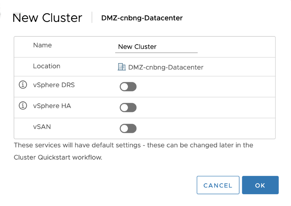
- Provide name of the cluster and click ok (all other options remain default)
- Now add a host to the cluster. By selecting add host from right click menu on newly created cluster. Follow on screen instructions to add the host.
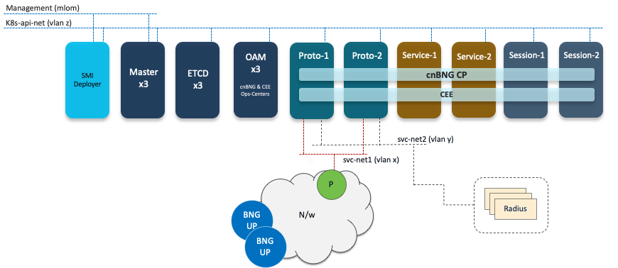
Deployment Logical Topology
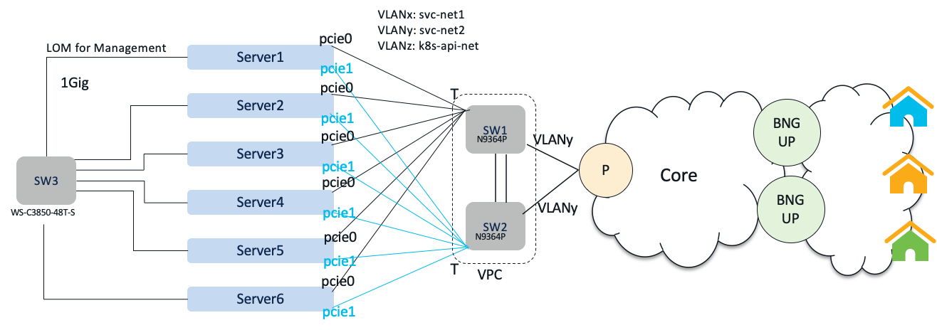
Physical Networking Topology
Step-1: VMWare ESXi Networking Preparation
We have following UCS hosts to deploy cnBNG CP
| Host IP | Datastore | VMs Deployed | |
|---|---|---|---|
| Server-1 | 10.81.103.64 | datastore01 | SMI Deployer, Master-1, ETCD-1, OAM-1 |
| Server-2 | 10.81.103.65 | datastore02 | Master-2, ETCD-2, OAM-2 |
| Server-3 | 10.81.103.66 | datastore03 | Master-3, ETCD-3, OAM-3 |
| Server-4 | 10.81.103.141 | datastore141 | proto1, service1 |
| Server-5 | 10.81.103.68 | datastore68 | proto2, session1 |
| Server-6 | 10.81.103.63 | datastore1 | service2, session2 |
We need following networks on ESXi hosts. Create following networks in VMWare ESXi by creating Port Groups, vSwitch and mapping vSwitches to correspinding vNICs.
| Network | Port Group | vSwitch | vNIC |
|---|---|---|---|
| svc-net1 | PCIE0_VLANx | vSwitch_PCIE0 | vnic corresponding to PCIE0 port |
| svc-net2 | PCIE0_VLANy | vSwitch_PCIE0 | vnic corresponding to PCIE0 port |
| k8s-api-net | PCIE0_VLANz | vSwitch_PCIE0 | vnic corresponding to PCIE0 port |
| k8s-api-net | PCIE1_VLANz | vSwitch_PCIE1 | vnic corresponding to PCIE1 port |
| Management | VM Network | vSwitch_LOM | vnic corresponding to LOM for management |
Note: VLANx, VLANy and VLANz could be based on the setup. In this tutorial we will be using z=312, y=311,x=310
We will be deploying total of 16 VMs, since this setup is production quality this ensures proper Resiliency in the cluster and labelling of nodes to help place PODs for optimal performance. Below table list the NIC attachment for each VM type.
| VM Name/Type | NIC1 | NIC2 | NIC3 |
|---|---|---|---|
| Inception/SMI Deployer | PCIE0_VLANz | VM Network | |
| master1 | PCIE0_VLANz | VM Network | |
| master2 | PCIE0_VLANz | VM Network | |
| master3 | PCIE0_VLANz | VM Network | |
| etcd1 | PCIE0_VLANz | ||
| etcd2 | PCIE0_VLANz | ||
| etcd3 | PCIE0_VLANz | ||
| oam1 | PCIE1_VLANz | ||
| oam2 | PCIE1_VLANz | ||
| oam3 | PCIE1_VLANz | ||
| proto1 | PCIE1_VLANz | PCIE1_VLANx | PCIE1_VLANy |
| proto2 | PCIE1_VLANz | PCIE1_VLANx | PCIE1_VLANy |
| service1 | PCIE0_VLANz | ||
| service2 | PCIE0_VLANz | ||
| session1 | PCIE0_VLANz | ||
| session2 | PCIE1_VLANz |
Note: VLANx, VLANy and VLANz could be based on the setup. In this tutorial we will be using z=312, y=311,x=310
Let us now look at the IP addressing we will be using for this deployment. In this tutorial we will use one External Management network (10.81.103.0/24) and an Internal network (212.212.212.0/24) for k8s operations. We will also attach two service networks: 11.0.0.0/24 and 12.0.0.0/24. svc-net1 (11.0.0.0/24) will be used for cnBNG CP and UP communication whereas svc-net2 (12.0.0.0/24) will be used for cnBNG CP and Radius communication.
| VM Name/Type | NIC1 IP | NIC2 IP | NIC3 IP |
|---|---|---|---|
| Inception/SMI Deployer | 212.212.212.100 | 10.81.103.100 | |
| master1 | 212.212.212.11 | 10.81.103.102 | |
| master2 | 212.212.212.12 | 10.81.103.103 | |
| master3 | 212.212.212.13 | 10.81.103.104 | |
| etcd1 | 212.212.212.14 | ||
| etcd2 | 212.212.212.15 | ||
| etcd3 | 212.212.212.16 | ||
| oam1 | 212.212.212.17 | ||
| oam2 | 212.212.212.18 | ||
| oam3 | 212.212.212.19 | ||
| proto1 | 212.212.212.20 | 11.0.0.2 | 12.0.0.2 |
| proto2 | 212.212.212.21 | 11.0.0.3 | 12.0.0.3 |
| service1 | 212.212.212.22 | ||
| service2 | 212.212.212.23 | ||
| session1 | 212.212.212.24 | ||
| session2 | 212.212.212.25 |
We would also need Virtual IPs which will be used keepalived between similar nodes to provide HA:
| VIP Type/Type | IP Address | Remarks |
|---|---|---|
| Master VIP1 | 10.81.103.101 | For management access |
| Master VIP2 | 212.212.212.101 | k8s-api-net access |
| Proto VIP1 | 212.212.212.102 | k8s-api-net access |
| Proto VIP2 | 11.0.0.1 | svc-net-1 VIP, will be used for peering with cnBNG UP |
| Proto VIP3 | 12.0.0.1 | svc-net-2 VIP, will be used for Radius communication |
Step 2: Inception Server Deployment
Follow the steps detailed before on Inception Server Deployment. However attach two NICs to Inception Server VM , as per the NIC attachment plan described in Step-1.
Step 3: SSH Key Generation
This is for security reasons, where cnBNG CP VM can only be accessed by ssh key and not through password by default.
- SSH Login to Inception VM
- Generate SSH key using:
ssh-keygen -t rsa
- Note down ssh keys in a file from .ssh/id_rsa (private) and ./ssh/id_rsa.pub (public)
- Remove line breaks from private key and replace them with string “\n”
- Remove line breaks from public key if there are any.
Step 4: cnBNG CP Cluster Configuration
- Let us first define the VMWare environment
environments vmware
 vcenter server         <<vcenter ip>>
 vcenter allow-self-signed-cert true
 vcenter user           <<your vcenter username>>
 vcenter password       <<your password>>
 vcenter datastore      <<server local datastore>>
 vcenter cluster        cnBNG_SMI_CL01
 vcenter datacenter     cnBNG_DC_01
 vcenter host           <<your host name>>
 vcenter nics "VM Network"
 exit
exit
- We will now define the software repos for cnBNG CP and CEE. cnBNG software is available as a tarball and it can be hosted on local http server for offline deployment. In this step we configure the software repository locations for tarball. We setup software cnf for both cnBNG CP and CEE. URL and SHA256 depends on the version of the image and the url location, so these two could change for your deployment.
software cnf bng
  url             http://192.168.107.148/your/image/location/bng.2021.04.m0.i74.tar
  sha256          e36b5ff86f35508539a8c8c8614ea227e67f97cf94830a8cee44fe0d2234dc1c
  description     bng-products
exit
software cnf cee
  url         http://192.168.107.148/your/image/location/cee-2020.02.6.i04.tar
  sha256      b5040e9ad711ef743168bf382317a89e47138163765642c432eb5b80d7881f57
  description cee-products
exit
- Next we define Cluster configuration based on our deployment schemel. The configuration is self explanatory. However do note two kinds of VIPs define here for master.
clusters cnbng-cp-cluster1
 environment vmware
 addons ingress bind-ip-address 10.81.103.101
 addons ingress bind-ip-address-internal 212.212.212.101
 addons ingress enabled
 addons istio enabled
 configuration master-virtual-ip        212.212.212.101
 configuration master-virtual-ip-cidr   24
 configuration master-virtual-ip-interface ens192
 configuration additional-master-virtual-ip 10.81.103.101
 configuration additional-master-virtual-ip-cidr 24
 configuration additional-master-virtual-ip-interface ens224
 configuration virtual-ip-vrrp-router-id 60
 configuration pod-subnet               192.212.0.0/16
 configuration allow-insecure-registry  true
 node-defaults initial-boot default-user username1
 node-defaults initial-boot default-user-ssh-public-key "ssh-rsa AAAAB3NzaC1yc2EAAAADAQABAAABAQDDH4uQdrxTvgFg32szcxLUfwrxmI513ySoDkjznncofvkL/JV122JAsGHvL6T39jBRKytuPpLhvr9ZvwKlOZ5BeeUB+Zj8tuZdQRqIpvonhtcESc11oRM6w5dQjHUIaDdK/vBQQg5hSQ0CVzvVU2DS8E+csMbBoPzaUVi+qPjqfBEt9MzMysc1DnnXN1fFMDVzTAsb5mgt/cLjcfbo6qVgLt9irFJ/AfoQGltQi9M4vehsprYZngGL5U9+qt9qn4lbaxTt2HqNQJAuk701LVhZNXKCfHmgg6en3IYk7YZI1IhhAnYAqlQLuC7df9DqE6i0iB8eTuRh5I2KsPUrCLGv cloud-user@inception"
 node-defaults initial-boot default-user-password password1
 node-defaults k8s ssh-username username1
 node-defaults k8s ssh-connection-private-key "-----BEGIN RSA PRIVATE KEY-----\nMIIEpAIBAAKCAQEAwx+LkHa8U74BYN9rM3MS1H8K8ZiOdd8kqA5I8553KH75C/yV\nddtiQLBh7y+k9/YwUSsrbj6S4b6/Wb8CpTmeQXnlAfmY/LbmXUEaiKb6J4bXBEnN\ndaETOsOXUIx1CGg3Sv7wUEIOYUkNAlc71VNg0vBPnLDGwaD82lFYvqj46nwRLfTM\nzMrHNQ551zdXxTA1c0wLG+ZoLf3C43H26OqlYC7fYqxSfwH6EBpbUIvTOL3obKa2\nGZ4Bi+VPfqrfap+JW2sU7dh6jUCQLpO9NS1YWTVygnx5oIOnp9yGJO2GSNSIYQJ2\nAKpUC7gu3X/Q6hOotIgfHk7kYeSNirD1KwixrwIDAQABAoIBADKgQKne5MYlil4E\nGeBjfwM7Yy+EEZJrrysbabor52bOave9NVo67aczHHXeusLLUYX92WrlOV7xCtzS\nPnF4HaOHaO+2PwdyvRp9BdFm4YjX53npXDGk9URN8zim+MaRo6cFtnxcZza+qW1u\nDMwwsfKI/178TtV2W6SZbpkpZkwQJ/cN1fljxuQYubOujMZErc1Q7TlIQYrG8XVz\naOTVkYBU+O2DOKkWp4AM9qe/0RIdjmz1ZZHRB83iF3/OaU3j2mhlhRQwTiS3jcGX\nkWoovz/GmFAcw+VSz81tz2UFmGNczkl8F5t4afYq31M7r+restSd6Mc7dcqWA7pR\nYflz7SECgYEA+qleQDAxe9cSRyGk0aCXV7NKQnvmIReSiRxibNne2FTnLaBH7iM7\nGe8XT23gFLCvM1qmpaLxjQZEP4A7WTaZuTEQAvVHYM+4m+1XDz4+ePaSCFwru8Q/\nLvE0h45JGfuHiXIWQNsyycSnDa+50BQ1a+EruzsmdHDvVnhO/QK0gzsCgYEAx0dg\nVbOjGzEvuGTfTI8qqRYz2XQjSKr6IHqRGY/h2hVcJo0Is+fr9n2QlebJ9oIOVnw7\npSlPgnMNcI9b74aCGuVnVUW/23TRkTvq6goNBa2V++d9EHPNo2gahc1tuJZzkp8I\nnZONBHzU8jwe9nBbK7uuz9i8cgSnMaWbS6Q8PB0CgYEAoXzoWdYyqyQ+hFEqjFs3\n5ap+lyKXeo5jO65rwtECfsEERyLR9JwCAY1FqUiSawIBfcZTQrcdg8ubwIVutuU0\nWFlBhYZcPATXXK2lvw5M1UWVg4lOK6QdSLLhMsv6UKD6CxTTPWl66P6m2Wxy+5lp\naV0h/Xf4KGBx8XWE/f/2J+0CgYEAlfJGMZZut4pGLwhv4WqkngBf2VMDLa3Bcejn\n/4T9W5zQ7w0WLFDpg1quDa1P8JWh9j+ancc81Zp+1WB5u/zJLzXIkChgmeAHxLGC\nLMKNU+VuwtJHj7ajWD6AHogZ9Ff49K2HzRH2fRb1IKROY/7dC0Y43ppmCaEosTm8\nZalZzZ0CgYAF6KnlPw1qbpVZYyVcPw38omeisMs/92ovf4oqzJpZ5zCW1iKKRpQR\nq4oDLca0zJS/AUmXFTIG//VHvsna4A2JrmNS4rI+bEgwSDrRKHmX8Idctdu1ifgS\nrRtv1s5RfTZ67eWVYE6rUn1+EFBZwAzZorOXL3CzbjZEXUCJeOH6Lw==\n-----END RSA PRIVATE KEY-----"
- Define Common Netplan for all VMs. We will only define k8s-api-net here. Based on attachments we will add new networks.
network:
    version: 2
    ethernets:
{ % if master_vm is defined and master_vm == 'true' %}
        ens192:
            addresses:
            - { {K8S_SSH_IP}}/24
            dhcp4: false
            routes:
            -   metric: 50
                to: 0.0.0.0/0
                via: 212.212.212.101
        ens224:
            dhcp4: false
            nameservers:
                addresses:
                - 64.102.6.247
                search:
                - cisco.com
            gateway4: 10.81.103.1   !! This is gateway IP for management
{ % else %}
        ens192:
            addresses:
            - { {K8S_SSH_IP}}/24
            dhcp4: false
            routes:
            -   metric: 50
                to: 0.0.0.0/0
                via: 212.212.212.101
{ % endif %}
Replace line breaks by “\n”. Netplan will look like this:
"network:\n version: 2\n ethernets:\n{ % if master_vm is defined and master_vm == 'true' %} \n ens192:\n addresses:\n - { {K8S_SSH_IP}}/24\n dhcp4: false\n routes:\n - metric: 50\n to: 0.0.0.0/0\n via: 212.212.212.101 \n ens224:\n dhcp4: false\n nameservers:\n addresses:\n - 64.102.6.247\n search:\n - cisco.com\n gateway4: 10.81.103.1 \n{ % else %}\n ens192:\n addresses:\n - { {K8S_SSH_IP}}/24\n dhcp4: false \n routes:\n - metric: 50\n to: 0.0.0.0/0\n via: 212.212.212.101 \n{ % endif %}\n"
- Apply netplan configurations
node-defaults netplan template "network:\n    version: 2\n    ethernets:\n{ % if master_vm is defined and master_vm == 'true' %}   \n        ens192:\n            addresses:\n            - { {K8S_SSH_IP}}/24\n            dhcp4: false\n            routes:\n            -   metric: 50\n                to: 0.0.0.0/0\n                via: 212.212.212.101                                        \n        ens224:\n            dhcp4: false\n            nameservers:\n                addresses:\n                - 64.102.6.247\n                search:\n                - cisco.com\n            gateway4: 10.81.103.1                                                     \n{ % else %}\n        ens192:\n            addresses:\n            - { {K8S_SSH_IP}}/24\n            dhcp4: false           \n            routes:\n            -   metric: 50\n                to: 0.0.0.0/0\n                via: 212.212.212.101    \n{ % endif %}\n"

node-defaults netplan variable-definitions master_vm
 default-value false
exit
- Will now apply NTP configurations for the cluster. If the reachability to NTP server is not available in K8s-api-net, then Inception Deployer can double up as the NTP server for the cluster VM nodes. In this tutorial we will use Inception Deployer as the NTP server
node-defaults os ntp enabled
node-defaults os ntp servers 212.212.212.100
exit
- Apply the master nodes configuration based on dimensioning and IP address scheme
nodes master1
  k8s node-type master
  k8s ssh-ip 212.212.212.11
  vmware datastore datastore01
  vmware host 10.81.103.64
  vmware performance memory-reservation true
  vmware performance cpu-reservation true
  vmware sizing ram-mb 16384
  vmware sizing cpus 4
  vmware sizing cores-equal-cpus true
  vmware sizing disk-root-gb 100
  vmware sizing disk-data-gb 100
  vmware sizing disk-home-gb 50
  vmware numa-node-affinity 0
  exit
  vmware nics PCIE0-VLAN312
  exit
  vmware nics "VM Network"
  exit
  netplan variables master_vm
   value true
  exit
  os netplan-additions ethernets ens224
   addresses [ 10.81.103.102/24 ]
  exit
  os ntp enabled
 exit
 nodes master2
  k8s node-type master
  k8s ssh-ip 212.212.212.12
  vmware datastore datastore02
  vmware host 10.81.103.65
  vmware performance memory-reservation true
  vmware performance cpu-reservation true
  vmware sizing ram-mb 16384
  vmware sizing cpus 4
  vmware sizing cores-equal-cpus true
  vmware sizing disk-root-gb 100
  vmware sizing disk-data-gb 100
  vmware sizing disk-home-gb 50
  vmware numa-node-affinity 0
  exit
  vmware nics PCIE0-VLAN312
  exit
  vmware nics "VM Network"
  exit
  netplan variables master_vm
   value true
  exit
  os netplan-additions ethernets ens224
   addresses [ 10.81.103.103/24 ]
  exit
  os ntp enabled
 exit
 nodes master3
  k8s node-type master
  k8s ssh-ip 212.212.212.13
  vmware datastore datastore03
  vmware host 10.81.103.66
  vmware performance memory-reservation true
  vmware performance cpu-reservation true
  vmware sizing ram-mb 16384
  vmware sizing cpus 4
  vmware sizing cores-equal-cpus true
  vmware sizing disk-root-gb 100
  vmware sizing disk-data-gb 100
  vmware sizing disk-home-gb 50
  vmware numa-node-affinity 0
  exit
  vmware nics PCIE0-VLAN312
  exit
  vmware nics "VM Network"
  exit
  netplan variables master_vm
   value true
  exit
  os netplan-additions ethernets ens224
   addresses [ 10.81.103.104/24 ]
  exit
  os ntp enabled
 exit
- Let’s now add ETCD node configurations
 nodes etcd1
  k8s node-type etcd
  k8s ssh-ip 212.212.212.14
  vmware datastore datastore01
  vmware host 10.81.103.64
  vmware performance memory-reservation true
  vmware performance cpu-reservation true
  vmware sizing ram-mb 16384
  vmware sizing cpus 4
  vmware sizing cores-equal-cpus true
  vmware sizing disk-root-gb 100
  vmware sizing disk-data-gb 100
  vmware sizing disk-home-gb 50
  vmware numa-node-affinity 0
  exit
  vmware nics PCIE0-VLAN312
  exit
  os ntp enabled
 exit
 nodes etcd2
  k8s node-type etcd
  k8s ssh-ip 212.212.212.15
  vmware datastore datastore02
  vmware host 10.81.103.65
  vmware performance memory-reservation true
  vmware performance cpu-reservation true
  vmware sizing ram-mb 16384
  vmware sizing cpus 4
  vmware sizing cores-equal-cpus true
  vmware sizing disk-root-gb 100
  vmware sizing disk-data-gb 100
  vmware sizing disk-home-gb 50
  vmware numa-node-affinity 0
  exit
  vmware nics PCIE0-VLAN312
  exit
  os ntp enabled
 exit
 nodes etcd3
  k8s node-type etcd
  k8s ssh-ip 212.212.212.16
  vmware datastore datastore03
  vmware host 10.81.103.66
  vmware performance memory-reservation true
  vmware performance cpu-reservation true
  vmware sizing ram-mb 16384
  vmware sizing cpus 4
  vmware sizing cores-equal-cpus true
  vmware sizing disk-root-gb 100
  vmware sizing disk-data-gb 100
  vmware sizing disk-home-gb 50
  vmware numa-node-affinity 0
  exit
  vmware nics PCIE0-VLAN312
  exit
  os ntp enabled
 exit
- Following is configuration for OAM nodes
 nodes oam1
  k8s node-type worker
  k8s ssh-ip 212.212.212.17
  k8s node-labels smi.cisco.com/node-type oam
  exit
  k8s node-labels smi.cisco.com/vm-type oam
  exit
  vmware datastore datastore01
  vmware host 10.81.103.64
  vmware performance memory-reservation true
  vmware performance cpu-reservation true
  vmware sizing ram-mb 114688
  vmware sizing cpus 12
  vmware sizing cores-equal-cpus true
  vmware sizing disk-root-gb 100
  vmware sizing disk-data-gb 200
  vmware sizing disk-home-gb 50
  vmware numa-node-affinity 1
  exit
  vmware nics PCIE1-VLAN312
  exit
  os ntp enabled
 exit
 nodes oam2
  k8s node-type worker
  k8s ssh-ip 212.212.212.18
  k8s node-labels smi.cisco.com/node-type oam
  exit
  k8s node-labels smi.cisco.com/vm-type oam
  exit
  vmware datastore datastore02
  vmware host 10.81.103.65
  vmware performance memory-reservation true
  vmware performance cpu-reservation true
  vmware sizing ram-mb 114688
  vmware sizing cpus 12
  vmware sizing cores-equal-cpus true
  vmware sizing disk-root-gb 100
  vmware sizing disk-data-gb 200
  vmware sizing disk-home-gb 50
  vmware numa-node-affinity 1
  exit
  vmware nics PCIE1-VLAN312
  exit
  os ntp enabled
 exit
 nodes oam3
  k8s node-type worker
  k8s ssh-ip 212.212.212.19
  k8s node-labels smi.cisco.com/node-type oam
  exit
  k8s node-labels smi.cisco.com/vm-type oam
  exit
  vmware datastore datastore03
  vmware host 10.81.103.66
  vmware performance memory-reservation true
  vmware performance cpu-reservation true
  vmware sizing ram-mb 114688
  vmware sizing cpus 12
  vmware sizing cores-equal-cpus true
  vmware sizing disk-root-gb 100
  vmware sizing disk-data-gb 200
  vmware sizing disk-home-gb 50
  vmware numa-node-affinity 1
  exit
  vmware nics PCIE1-VLAN312
  exit
  os ntp enabled
 exit
- Apply below protocol nodes configurations
nodes proto1
  k8s node-type worker
  k8s ssh-ip 212.212.212.20
  k8s node-labels disktype ssd
  exit
  k8s node-labels smi.cisco.com/node-type protocol
  exit
  k8s node-labels smi.cisco.com/vm-type protocol
  exit
  vmware datastore datastore141
  vmware host 10.81.103.141
  vmware performance memory-reservation true
  vmware performance cpu-reservation true
  vmware sizing ram-mb 143360
  vmware sizing cpus 18
  vmware sizing cores-equal-cpus true
  vmware sizing disk-root-gb 100
  vmware sizing disk-data-gb 100
  vmware sizing disk-home-gb 50
  vmware numa-node-affinity 1
  exit
  vmware nics PCIE1-VLAN312
  exit
  vmware nics PCIE1-VLAN310
  exit
  vmware nics PCIE1-VLAN311
  exit
  os netplan-additions ethernets ens224
   addresses [ 11.0.0.2/24 ]
  exit
  os netplan-additions ethernets ens256
   addresses [ 12.0.0.2/24 ]
  exit
  os ntp enabled
 exit
 nodes proto2
  k8s node-type worker
  k8s ssh-ip 212.212.212.21
  k8s node-labels disktype ssd
  exit
  k8s node-labels smi.cisco.com/node-type protocol
  exit
  k8s node-labels smi.cisco.com/vm-type protocol
  exit
  vmware datastore datastore68
  vmware host 10.81.103.68
  vmware performance memory-reservation true
  vmware performance cpu-reservation true
  vmware sizing ram-mb 143360
  vmware sizing cpus 18
  vmware sizing cores-equal-cpus true
  vmware sizing disk-root-gb 100
  vmware sizing disk-data-gb 100
  vmware sizing disk-home-gb 50
  vmware numa-node-affinity 1
  exit
  vmware nics PCIE1-VLAN312
  exit
  vmware nics PCIE1-VLAN310
  exit
  vmware nics PCIE1-VLAN311
  exit
  os netplan-additions ethernets ens224
   addresses [ 11.0.0.3/24 ]
  exit
  os netplan-additions ethernets ens256
   addresses [ 12.0.0.3/24 ]
  exit
  os ntp enabled
 exit
- Add below Service and Session node configurations
 nodes service1
  k8s node-type worker
  k8s ssh-ip 212.212.212.22
  k8s node-labels smi.cisco.com/node-type service
  exit
  k8s node-labels smi.cisco.com/vm-type service
  exit
  vmware datastore datastore141
  vmware host 10.81.103.141
  vmware performance memory-reservation true
  vmware performance cpu-reservation true
  vmware sizing ram-mb 143360
  vmware sizing cpus 18
  vmware sizing cores-equal-cpus true
  vmware sizing disk-root-gb 100
  vmware sizing disk-data-gb 100
  vmware sizing disk-home-gb 50
  vmware numa-node-affinity 0
  exit
  vmware nics PCIE0-VLAN312
  exit
  os ntp enabled
 exit
 nodes service2
  k8s node-type worker
  k8s ssh-ip 212.212.212.23
  k8s node-labels smi.cisco.com/node-type service
  exit
  k8s node-labels smi.cisco.com/vm-type service
  exit
  vmware datastore datastore1
  vmware host 10.81.103.63
  vmware performance memory-reservation true
  vmware performance cpu-reservation true
  vmware sizing ram-mb 143360
  vmware sizing cpus 18
  vmware sizing cores-equal-cpus true
  vmware sizing disk-root-gb 100
  vmware sizing disk-data-gb 100
  vmware sizing disk-home-gb 50
  vmware numa-node-affinity 0
  exit
  vmware nics PCIE0-VLAN312
  exit
  os ntp enabled
 exit
 nodes session1
  k8s node-type worker
  k8s ssh-ip 212.212.212.24
  k8s node-labels smi.cisco.com/node-type session
  exit
  k8s node-labels smi.cisco.com/vm-type session
  exit
  vmware datastore datastore68
  vmware host 10.81.103.68
  vmware performance memory-reservation true
  vmware performance cpu-reservation true
  vmware sizing ram-mb 143360
  vmware sizing cpus 18
  vmware sizing cores-equal-cpus true
  vmware sizing disk-root-gb 100
  vmware sizing disk-data-gb 100
  vmware sizing disk-home-gb 50
  vmware numa-node-affinity 0
  exit
  vmware nics PCIE0-VLAN312
  exit
  os ntp enabled
 exit
 nodes session2
  k8s node-type worker
  k8s ssh-ip 212.212.212.25
  k8s node-labels smi.cisco.com/node-type session
  exit
  k8s node-labels smi.cisco.com/vm-type session
  exit
  vmware datastore datastore1
  vmware host 10.81.103.63
  vmware performance memory-reservation true
  vmware performance cpu-reservation true
  vmware sizing ram-mb 143360
  vmware sizing cpus 18
  vmware sizing cores-equal-cpus true
  vmware sizing disk-root-gb 100
  vmware sizing disk-data-gb 100
  vmware sizing disk-home-gb 50
  vmware numa-node-affinity 1
  exit
  vmware nics PCIE1-VLAN312
  exit
  os ntp enabled
 exit
- We now need to define the virtual IPs.
virtual-ips udpvip
  check-ports    [ 28000 ]
  vrrp-interface ens192
  vrrp-router-id 222
  check-interface ens192
  exit
  check-interface ens224
  exit
  check-interface ens256
  exit
  ipv4-addresses 212.212.212.102
   mask      24
   broadcast 212.212.212.255
   device    ens192
  exit
  ipv4-addresses 11.0.0.1
   mask      24
   broadcast 11.0.0.255
   device    ens224
  exit
  ipv4-addresses 12.0.0.1
   mask      24
   broadcast 12.0.0.255
   device    ens256
  exit
  hosts proto1
   priority 100
  exit
  hosts proto2
   priority 100
  exit
 exit
- Let’s define ops-center config
clusters cnbng-cp-cluster1
 ops-centers bng bng
  repository-local        bng
  sync-default-repository true
  netconf-ip              10.81.103.101
  netconf-port            2022
  ssh-ip                  10.81.103.101
  ssh-port                2024
  ingress-hostname        10.81.103.101.nip.io
  initial-boot-parameters use-volume-claims true
  initial-boot-parameters first-boot-password password1
  initial-boot-parameters auto-deploy false
  initial-boot-parameters single-node true
 exit
 ops-centers cee global
  repository-local        cee
  sync-default-repository true
  netconf-ip              10.81.103.101
  netconf-port            3024
  ssh-ip                  10.81.103.101
  ssh-port                3023
  ingress-hostname        10.81.103.101.nip.io
  initial-boot-parameters use-volume-claims true
  initial-boot-parameters first-boot-password password1
  initial-boot-parameters auto-deploy true
  initial-boot-parameters single-node true
 exit
exit
Step 5: cnBNG CP Deployment
- After committing configuration which we build in Step-4 on SMI Deployer. We can start the cluster sync.
[inception] SMI Cluster Deployer# clusters cnbng-cp-cluster1 actions sync run
This will run sync.  Are you sure? [no,yes] yes
message accepted
[inception] SMI Cluster Deployer#
- Monitor sync using below command. It will take about 90mins to sync and deploy the cluster.
monitor sync-logs cnbng-cp-cluster1

E.g.

[inception] SMI Cluster Deployer# monitor sync-logs cnbng-cp-cluster1
. . .
. . .

Thursday 18 November 2021  14:38:49 +0000 (0:00:00.064)       0:08:42.748 *****
===============================================================================
2021-11-18 14:38:49.716 DEBUG cluster_sync.cnbng-cp-cluster1: Cluster sync successful
2021-11-18 14:38:49.717 DEBUG cluster_sync.cnbng-cp-cluster1: Ansible sync done
2021-11-18 14:38:49.717 INFO cluster_sync.cnbng-cp-cluster1: _sync finished.  Opening lock
Verifications
After the cluster is deployed it can be verified using below commands
- Connect to K8s Master node using SSH with Master VIP1 IP
ssh cisco@master-vip1-ip
- After connecting verify that all PODs are in Running state
kubectl get pods -A
- Verify nodes in cnBNG Cluster using
kubectl get nodes
- We can connect to Grafana at the grafana ingress
kubectl get ingress -A
- SSH to cnBNG CP Ops Center at port 2024
cloud-user@inception:~$ ssh [email protected] -p 2024
[email protected]'s password:

      Welcome to the bng CLI on pod2/bng
      Copyright © 2016-2020, Cisco Systems, Inc.
      All rights reserved.

User admin last logged in 2021-11-19T04:12:32.912093+00:00, to ops-center-bng-bng-ops-center-77fb6479fc-dtvt2, from 10.81.103.101 using cli-ssh
admin connected from 10.81.103.101 using ssh on ops-center-bng-bng-ops-center-77fb6479fc-dtvt2
[pod1/bng] bng#
[pod1/bng] bng#
- We can also test Netconf Interface availability of cnBNG Ops Center using ssh
cloud-user@inception:~$ ssh [email protected] -p 3022 -s netconf
Warning: Permanently added '[10.81.103.101]:3022' (RSA) to the list of known hosts.
[email protected]'s password:
<?xml version="1.0" encoding="UTF-8"?>
<hello xmlns="urn:ietf:params:xml:ns:netconf:base:1.0">
<capabilities>
<capability>urn:ietf:params:netconf:base:1.0</capability>
<capability>urn:ietf:params:netconf:base:1.1</capability>
<capability>urn:ietf:params:netconf:capability:confirmed-commit:1.1</capability>
<capability>urn:ietf:params:netconf:capability:confirmed-commit:1.0</capability>
<capability>urn:ietf:params:netconf:capability:candidate:1.0</capability>
<capability>urn:ietf:params:netconf:capability:rollback-on-error:1.0</capability>
<capability>urn:ietf:params:netconf:capability:url:1.0?scheme=ftp,sftp,file</capability>
<capability>urn:ietf:params:netconf:capability:validate:1.0</capability>
<capability>urn:ietf:params:netconf:capability:validate:1.1</capability>
<capability>urn:ietf:params:netconf:capability:xpath:1.0</capability>
<capability>urn:ietf:params:netconf:capability:notification:1.0</capability>
<capability>urn:ietf:params:netconf:capability:interleave:1.0</capability>
<capability>urn:ietf:params:netconf:capability:partial-lock:1.0</capability>
<capability>urn:ietf:params:netconf:capability:with-defaults:1.0?basic-mode=explicit&also-supported=report-all-tagged,report-all</capability>
<capability>urn:ietf:params:netconf:capability:yang-library:1.0?revision=2019-01-04&module-set-id=a6803bdbd5c766b47137ad86700fff0a</capability>
<capability>urn:ietf:params:netconf:capability:yang-library:1.1?revision=2019-01-04&content-id=a6803bdbd5c766b47137ad86700fff0a</capability>
<capability>http://tail-f.com/ns/netconf/actions/1.0</capability>
<capability>http://cisco.com/cisco-bng-ipam?module=cisco-bng-ipam&revision=2020-01-24</capability>
<capability>http://cisco.com/cisco-cn-ipam?module=cisco-cn-ipam&revision=2021-02-21</capability>
<capability>http://cisco.com/cisco-exec-ipam?module=cisco-exec-ipam&revision=2021-06-01</capability>
<capability>http://cisco.com/cisco-mobile-nf-tls?module=cisco-mobile-nf-tls&revision=2020-06-24</capability>
<capability>http://cisco.com/cisco-smi-etcd?module=cisco-smi-etcd&revision=2021-09-15</capability>
<capability>http://tail-f.com/cisco-mobile-common?module=tailf-mobile-common&revision=2019-04-25</capability>
<capability>http://tail-f.com/cisco-mobile-product?module=tailf-cisco-mobile-product&revision=2018-06-06</capability>
<capability>http://tail-f.com/ns/aaa/1.1?module=tailf-aaa&revision=2018-09-12</capability>
<capability>http://tail-f.com/ns/common/query?module=tailf-common-query&revision=2017-12-15</capability>
<capability>http://tail-f.com/ns/confd-progress?module=tailf-confd-progress&revision=2020-06-29</capability>
<capability>http://tail-f.com/ns/kicker?module=tailf-kicker&revision=2020-11-26</capability>
<capability>http://tail-f.com/ns/netconf/query?module=tailf-netconf-query&revision=2017-01-06</capability>
<capability>http://tail-f.com/ns/webui?module=tailf-webui&revision=2013-03-07</capability>
<capability>http://tail-f.com/yang/acm?module=tailf-acm&revision=2013-03-07</capability>
<capability>http://tail-f.com/yang/common?module=tailf-common&revision=2020-11-26</capability>
<capability>http://tail-f.com/yang/common-monitoring?module=tailf-common-monitoring&revision=2019-04-09</capability>
<capability>http://tail-f.com/yang/confd-monitoring?module=tailf-confd-monitoring&revision=2019-10-30</capability>
<capability>http://tail-f.com/yang/last-login?module=tailf-last-login&revision=2019-11-21</capability>
<capability>http://tail-f.com/yang/netconf-monitoring?module=tailf-netconf-monitoring&revision=2019-03-28</capability>
<capability>http://tail-f.com/yang/xsd-types?module=tailf-xsd-types&revision=2017-11-20</capability>
<capability>urn:ietf:params:xml:ns:netconf:base:1.0?module=ietf-netconf&revision=2011-06-01&features=confirmed-commit,candidate,rollback-on-error,validate,xpath,url</capability>
<capability>urn:ietf:params:xml:ns:netconf:partial-lock:1.0?module=ietf-netconf-partial-lock&revision=2009-10-19</capability>
<capability>urn:ietf:params:xml:ns:yang:iana-crypt-hash?module=iana-crypt-hash&revision=2014-08-06&features=crypt-hash-sha-512,crypt-hash-sha-256,crypt-hash-md5</capability>
<capability>urn:ietf:params:xml:ns:yang:ietf-inet-types?module=ietf-inet-types&revision=2013-07-15</capability>
<capability>urn:ietf:params:xml:ns:yang:ietf-netconf-acm?module=ietf-netconf-acm&revision=2018-02-14</capability>
<capability>urn:ietf:params:xml:ns:yang:ietf-netconf-monitoring?module=ietf-netconf-monitoring&revision=2010-10-04</capability>
<capability>urn:ietf:params:xml:ns:yang:ietf-netconf-notifications?module=ietf-netconf-notifications&revision=2012-02-06</capability>
<capability>urn:ietf:params:xml:ns:yang:ietf-netconf-with-defaults?module=ietf-netconf-with-defaults&revision=2011-06-01</capability>
<capability>urn:ietf:params:xml:ns:yang:ietf-restconf-monitoring?module=ietf-restconf-monitoring&revision=2017-01-26</capability>
<capability>urn:ietf:params:xml:ns:yang:ietf-x509-cert-to-name?module=ietf-x509-cert-to-name&revision=2014-12-10</capability>
<capability>urn:ietf:params:xml:ns:yang:ietf-yang-metadata?module=ietf-yang-metadata&revision=2016-08-05</capability>
<capability>urn:ietf:params:xml:ns:yang:ietf-yang-types?module=ietf-yang-types&revision=2013-07-15</capability>
</capabilities>
<session-id>171</session-id></hello>]]>]]>
Initial cnBNG CP Configurations
If you have deployed cnBNG CP a fresh then most probably, initial cnBNG CP configuration is not applied on Ops Center. Follow below steps to apply initial configuratuon to cnBNG CP Ops Center
- SSH login to cnBNG CP Ops Center CLI
cisco@pod100-cnbng-cp:~$ ssh [email protected] -p 2024
Warning: Permanently added '[10.81.103.101]:2024' (RSA) to the list of known hosts.
[email protected]'s password:

      Welcome to the bng CLI on pod100/bng
      Copyright © 2016-2020, Cisco Systems, Inc.
      All rights reserved.

User admin last logged in 2021-12-01T11:42:45.247257+00:00, to ops-center-bng-bng-ops-center-5666d4cb6-dj7sv, from 10.81.103.101 using cli-ssh
admin connected from 10.81.103.101 using ssh on ops-center-bng-bng-ops-center-5666d4cb6-dj7sv
[pod100/bng] bng#
- Change to config mode in Ops Center
[pod100/bng] bng# config
Entering configuration mode terminal
[pod100/bng] bng(config)#
- Apply following initial configuration. With changes to “endpoint radius” and “udp proxy” configs. Both “endpoint radius” and “udp-proxy” should use IP of cnBNG CP service network side protocol VIP or in case of AIO it should be the IP of AIO VM used for peering between cnBNG CP and UP.
cdl node-type session
cdl logging default-log-level error
cdl datastore session
 slice-names [ 1 ]
 endpoint replica 2
 endpoint copies-per-node 2
 endpoint settings slot-timeout-ms 750
 index replica 2
 index map 1
 slot replica 2
 slot map 4
 slot notification limit           1200
 slot notification max-concurrent-bulk-notifications 20
exit
cdl kafka replica 2
etcd backup disable true
instance instance-id 1
 endpoint sm
  replicas 3
  nodes    2
 exit
 endpoint l2tp-tunnel
  replicas 1
  nodes    2
 exit
 endpoint nodemgr
  replicas 1
  nodes    2
 exit
 endpoint n4-protocol
  replicas 1
  nodes    2
  retransmission timeout 0 max-retry 1
 exit
 endpoint dhcp
  replicas 1
  nodes    2
 exit
 endpoint pppoe
  replicas 1
  nodes    2
 exit
 endpoint radius
  replicas 1
  nodes    2
!! Change this IP to svc-net1 related VIP (Proto VIP2)
  vip-ip 11.0.0.1
  interface coa-nas
   sla response 25000
   vip-ip 11.0.0.1 vip-port 3799
  exit
 exit
 endpoint udp-proxy
  replicas     1
  nodes        2
!! Change this IP to k8s-api-net related VIP (Proto VIP1)
  internal-vip 212.212.212.102
!! Change this IP to svc-net2 related VIP (Proto VIP3)
  vip-ip 12.0.0.1
  interface n4
   sla response 25000
  exit
  interface gtpu
   sla response 25000
  exit
 exit
exit
logging transaction duplicate disable
logging level application error
logging level transaction error
logging level tracing error
logging error stack disable
logging name bng-dhcp0.bngfsol.collision
logging name infra.application.core level application error
logging name infra.config.core level application error
logging name infra.config.core level transaction error
logging name infra.dispatcher.core
logging name infra.heap_dump.core level application error
logging name infra.heap_dump.core level transaction error
logging name infra.memory_cache.core level application error
logging name infra.session_cache.core
deployment
 app-name     BNG
!! Change below cluster-name to your cluster name
 cluster-name Local
 dc-name      DC
exit
k8 bng
 etcd-endpoint      etcd:2379
 datastore-endpoint datastore-ep-session:8882
 tracing
  enable
  enable-trace-percent 30
  append-messages      true
  endpoint             jaeger-collector:9411
 exit
exit
k8 label protocol-layer key smi.cisco.com/vm-type value protocol
exit
k8 label service-layer key smi.cisco.com/vm-type value service
exit
k8 label cdl-layer key smi.cisco.com/vm-type value session
exit
k8 label oam-layer key smi.cisco.com/vm-type value oam
exit
instances instance 1
 system-id  DC
 cluster-id Local
 slice-name 1
exit
local-instance instance 1
- Put system in running mode and commit the changes
[pod100/bng] bng(config)# system mode running
[pod100/bng] bng(config)# commit
Commit complete.
[pod100/bng] bng(config)#
Message from confd-api-manager at 2021-12-01 12:36:05...
Helm update is STARTING.  Trigger for update is STARTUP.
[pod100/bng] bng(config)#
Message from confd-api-manager at 2021-12-01 12:36:08...
Helm update is SUCCESS.  Trigger for update is STARTUP.
Credits: Special thanks to Sripada Rao for providing configurations from SVI.
Leave a Comment