
Multicast Distribution Trees - MDTs
MVPN Overview
Many thanks to Anuj Budhiraja, Cisco Technical Lead Engineer, for his help writting this blog!
In this blog, we will cover MVPN (Multicast VPN) and the Multicast Distribution Trees (MDT). In Unicast VPN, once the transport underlay is set, any VPN instance or any VRF instance can use the exact same transport but in Multicast this is not the case.
The instances might be using different VPNs, Red or Blue. If these instances are using the same transport then the traffic designated to Red will be forwarded to Green and this is not acceptable. Thus, for each VPN instance we have to build a separate transport underlay. We can come up with an example based on the following snapshot.
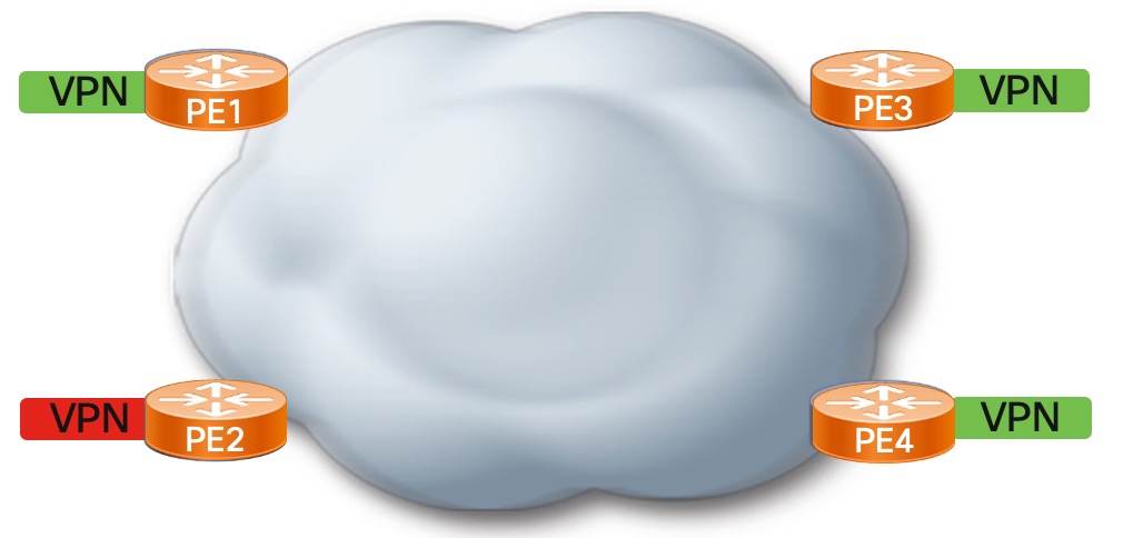
VPNs
We assume that we have 4 PEs (PE1, PE2, PE3, PE4) and only one of them has 1 subset VPN instance. For example PE1, PE3 and PE4 use a Green VPN, while PE2 uses a Red VPN. In this case, if we use a common transport underlay then there will be a mix of traffic. Red VPN will be receiving traffic from Green and vice-versa. This is why we need to come up with a new transport underlay.
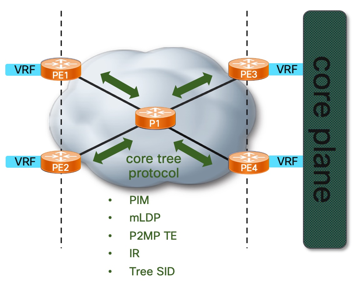
Underlay
The first step is to build a core plane (underlay) in the network. We need to use a core tree protocol such as PIM, mLDP, P2MP TE, Tree-SID or IR.
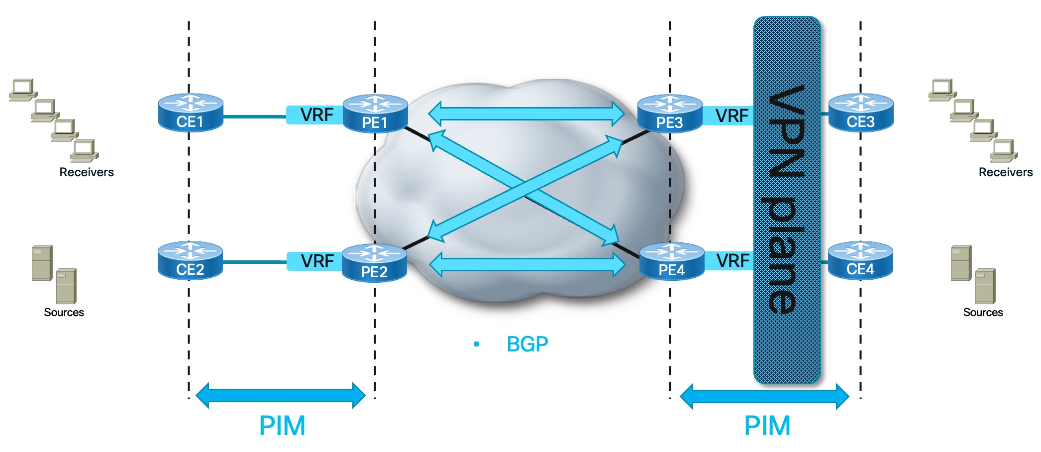
Overlay
To build the overlay we are adding the customer boxes and PE devices that are already aware of the above underlay. There are 2 common protocols to be used here, PIM or IGMP. If the switch is directly connected to the PE then we configure PIM between the CE and the PE. For the connectivity between the PEs we either use BGP Signaling or PIM Signaling. For MVPN profile 14 we use BGP Signaling.
Core Tree Types
They are called MDT (Multicast Distribution Tree) or PMSI (Provider Multicast Service Interface, IETF naming). They can be built with any of the transport core protocols previously mentioned based on the MVPN profile used.
Default MDT or Multidirectional Inclusive PMSI (MI-PMSI)
All the PEs that belong in the same MVPN, are all connected together bidirectional, which means any traffic sent to a PE will be received by all the PEs. This MDT will always be present no matter if there is traffic or not.
- Connects all PEs
- Bidirectional
- Always present
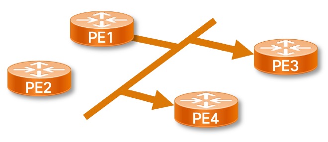
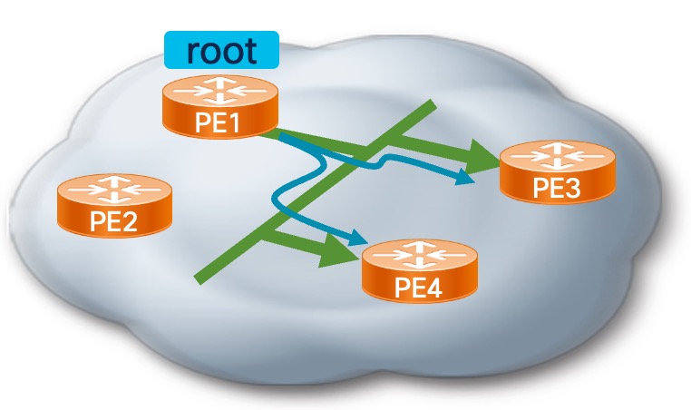
Data MDT or Selective PMSI (S-PMSI)
There is a PE (PE1) which is the Source or the Root and it is connected to a subset of PEs (PE3 and PE4), thus traffic will be received by them only.
- Connects subset of PEs
- Unidirectional (operating in a single direction)
- On-Demand (config exists but it is triggered when parameters are met)
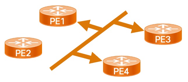
Partitioned MDT or Multidirectional Selective PMSI (MS-PMSI)
It is a combination of the previous two.
- Connects subset of PEs
- Uni- or Bidirectional
- On-Demand (a Join request will trigger the creation of the Tree)
Core Tree Type Construction - mLDP POV
Default MDT
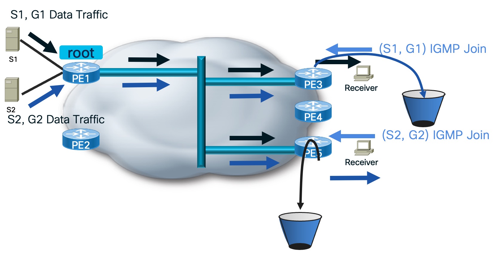
In the following Default MDT scenario we have 4 PEs, where PE1 is the Root and creates the MDT towards all 3 PEs. All the PEs act as the Root at once, trying to send the information to all PEs and all the PEs join that Tree. Thus we have a full mesh of P2MP mLDP Trees.
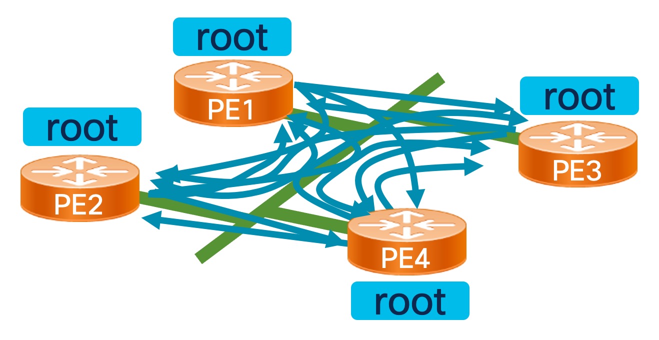
We will follow the next steps to simulate the creation of the Default MDT Trees.
- Tree is built upon configuration. The way it is built, is based on the Core Tree Protocol used.
- All PEs are connected to each other
- There is a receiver directly connected to PE3 and sends (S1, G1) IGMP Join
- PE3 will look at the Source1 IP address and check how it can be reached. The reachability is in the VPN context through PE1
- The PE1 receives that and starts building the Tree towards the Source
- It can be directly connected Source, thus we do not need to do anything
- It can be connected to a CE, thus PIM would be the protocol to use (PIM Joins)
- Traffic starts flowing and it is flooded to all the PEs
- Since only PE3 is interested in this traffic, the rest of the PEs will drop it
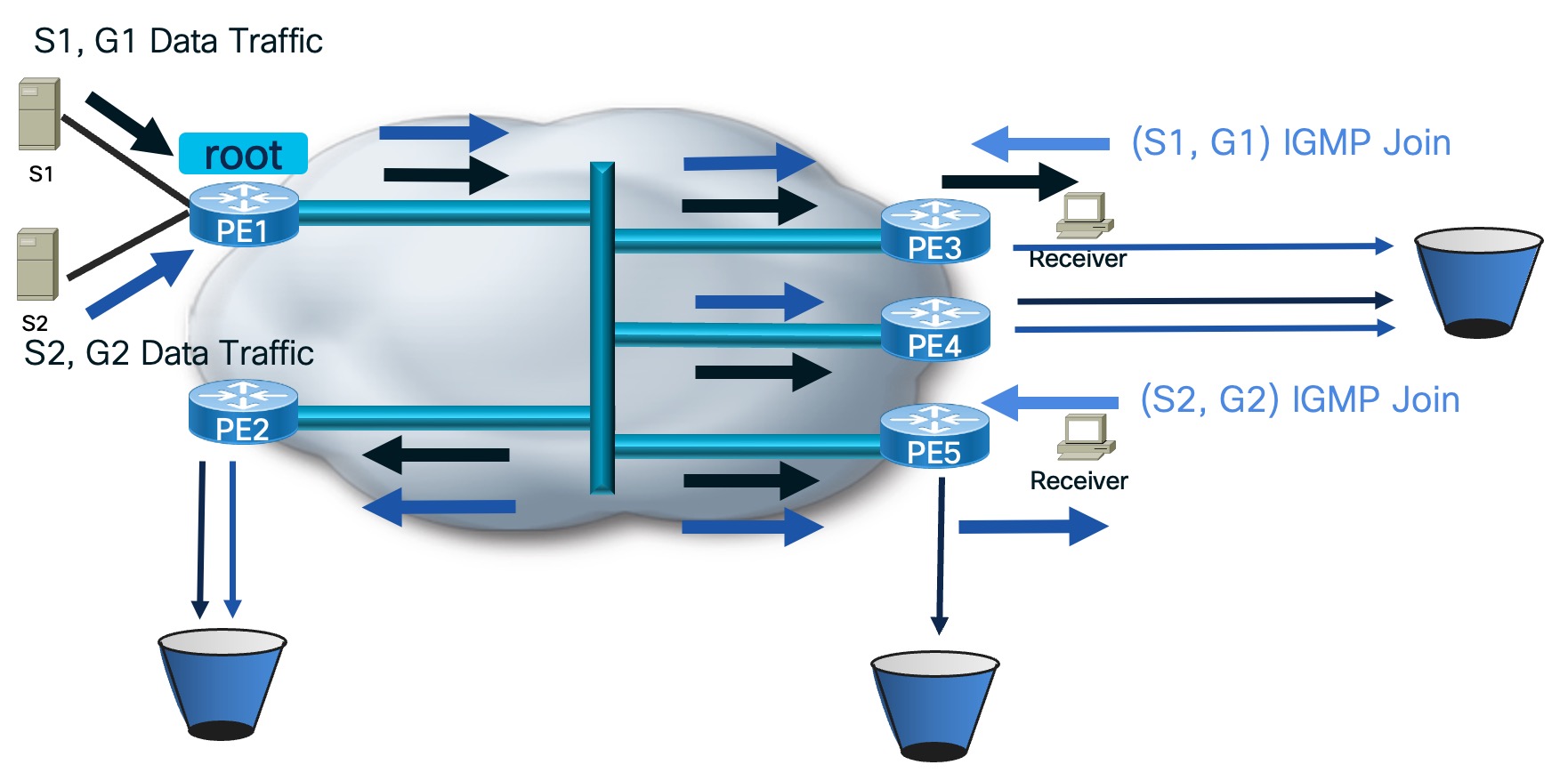
We would have the same outcome in case we had a receiver behind a different PE with different or same Source. The caveat of Default MDT is the drop of multicast traffic on egress PE, if there is no receiver.
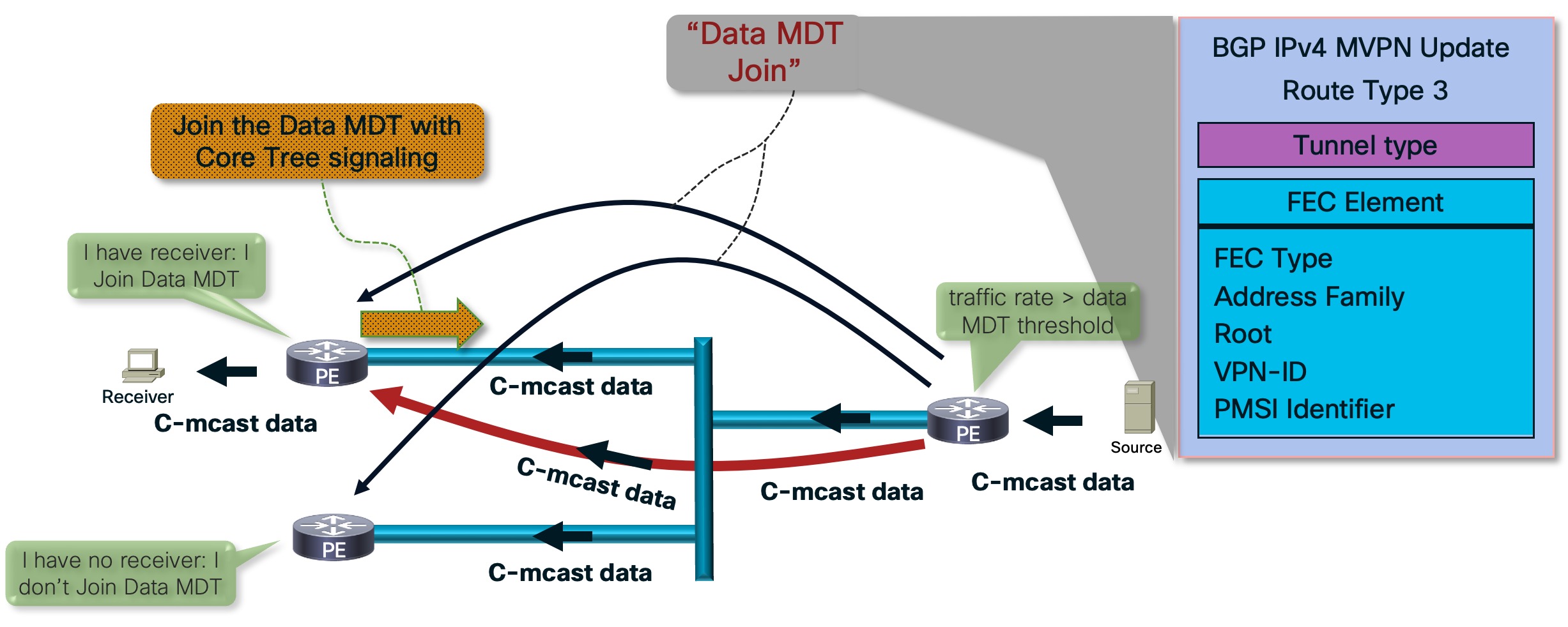
Data MDT
In the following Data MDT scenario we have a unidirectional MDT with only a subset of PEs joining the Tree. PE1 is the Root and distributes the traffic to the connected PEs. Thus we have a P2MP mLDP Tree.
We will follow the next steps to simulate the execution of Data MDT.
- All PEs are connected and receiving multicast traffic
- There is only 1 receiver behind the PE
- The PE connected to the Source sends a Route Type 3 message to all the participating PEs which Tree to join, only if the traffic rate > data MDT threshold (in case of applied threshold configuration)
- The PEs with the receivers who are interested in this traffic will join the Data MDT via Core Tree Signaling (mLDP, Tree-SID, IR) and Tree gets built
- Traffic will only be forwarded through that Tree
Partitioned MDT
Depending on whether it is bidirectional or unidirectional, it will be similar to Default or Data MDT.
We will follow the next steps to simulate the creation of a Dynamic version of Default MDT model. We start with 5 PEs with no connection yet to each other.
- We have a receiver directly connected to PE3 which sends (S1, G1) IGMP Join
- PE3 will look at the Source1 IP address and check how it can be reached. The reachability is in the VPN context through PE1
- PE3 starts creating the Tree to PE1 which consists of a link between PE1 and PE3 (no other PEs are connected)
- The Tree has been created and the PE1 gets the traffic for the receiver behind PE3
Now we can assume that there is another receiver behind PE5 with a different Source (Source2)
- Receiver sends (S2, G2) IGMP Join to PE5
- Based on the configuration of the transport protocol on the core, PE5 can join the same Tree that has already been built for PE3
- The traffic flows from S1 to PE1 and PE3 to PE5
- The PE5 drops this traffic
- The traffic flows from S2 to PE1 and PE3 to PE5
- The PE3 drops this traffic
- Thus, all receivers that have joined this Tree, drop the traffic that is not requested by their designated receiver
Default MDT vs Partitioned MDT
- The receivers in Partitioned MDT will not receive any unwanted traffic compared to Default
- In Partitioned MDT once the Join goes away the Tree is pruned
- The Partitioned MDT is exactly the same with Default, if all the receivers are active at the same time
Auto-Discovery
The process of discovering all the PEs with members in a given MVPN is the way a MDT is built. In the examples we are using BGP Auto-Discovery and BGP Signaling. Upon the enablement of the configuration, BGP enables address families. In Multicast, we have BGP IPv4 MVPN address family and upon enabling that we can discover all the PEs that are part of the specific MVPN.
Conclusion
This blog covered the definition of the MDTs and the different types that are being used today. There are 26 MVPN Profiles that use Default, Partitioned and Data MDTs. More information about the configuration can be found here:
More information about MDTs can be found in the follow Cisco Live sessions:
More information about Data MDT considerations while deploying MVPN Profile 14:
Leave a Comment