Multicast
Introduction to Multicast on NCS-5500
This introduction will be the start of a new series in the NCS-5500 xrdocs family called “Introduction to Multicast on NCS-5500”. NCS5500 is an important member of Cisco’s portfolio like ASR 9000 and 8000, however is not as heavily represented as ASR 9000. This series is an opportunity to learn more about NCS5500 and decide which platform is more suitable to your needs. It will focus mostly on multicast and will try to cover the most popular features on this. unveil strengths and weaknesses and compare the capabilities of NCS-5500 to the rest of CIsco’s portfolio.
Introduction to packet replication
This is the first blog spot of the new series and will cover the most important part, which is how is multicast replicated. In the following link Packet buffering you can find information about packet buffering and how is unicast traffic scheduled on ncs5500.
NCS 5500 System Architecture
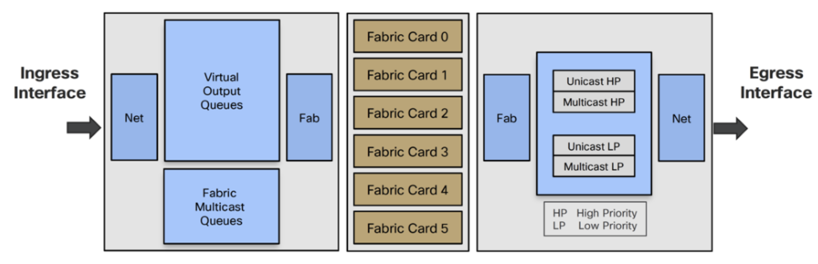
Multicast replication is a two-stage process. The process starts in the fabric to send a copy to the NPUs which are interested in the flow and then each NPU performs the second level of replication to interfaces interested in receiving the traffic. There is not ingress replication in the current version of the platform. Multicast packets are transmitted and replicated without egress scheduler approval which is opposite to unicast traffic. Even if you are using a single chipset system, the packets will still be split in cells. If the packet is going out of the same interface, it will always go with the form of a cell internally.
Multicast packet ingress pipeline processing
Control plane: The packets are punted to the line card CPU and are passed to different processes. It is checked if an MCID (Multicast ID) already exists and if it does not a new one is created. If one already exists it is updated with the new multicast pairs. Two tables are created, MCID mapping table which is a 128 bitmap mask where Ones represent NPUs who received a join and expect a copy of the packet from fabric and MCID-DB which associates ports where a replication is expected.
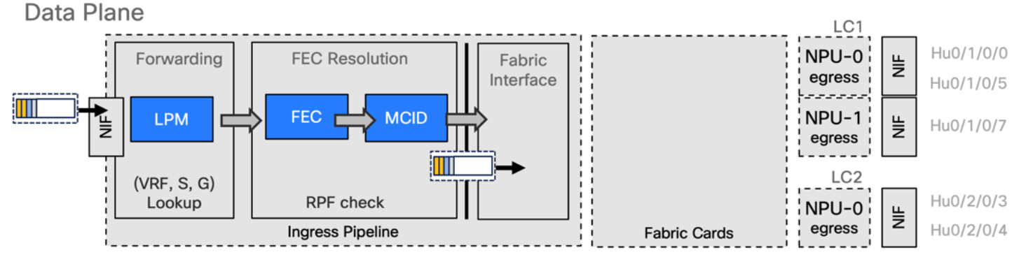
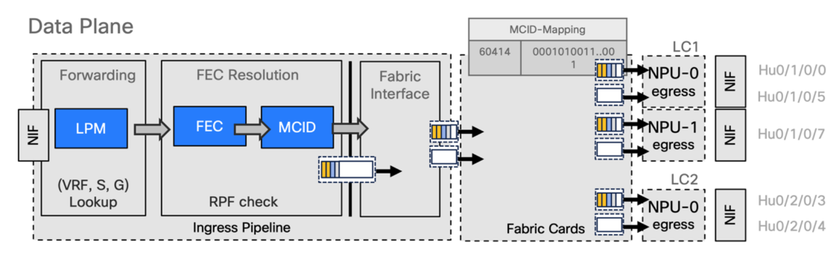
Data plane: Multicast packet is received on ingress interface and there are two places where packets are stored, L3 packets go to LPM* and L2 packets go to iTCAM. We receive the packet, we have a lookup on the forwarding block of the ingress pipeline that will perform a resolution inside the FEC, and it will point to a MCID and then the packet will be sent to the fabric and will be split in cells.
Multicast packet ingress pipeline processing
There is a good reason Multicast is not scheduled and this is explained below.
- Packet “a” needs to be replicated to multiple interfaces but one is full
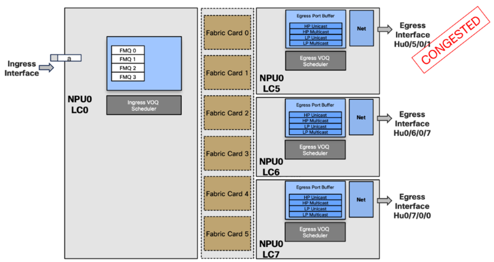
If we use a scheduled based system, in a scenario such as the above and we need to replicate a packet in multiple interfaces, and one is congested then it will not give the right to the packet to transmit. Meaning that the line cards LC6 and LC7 will not receive this copy of the packet. This is called head-of-line blocking Head of line blocking. We cannot rely on tokens for permission to be transmitted, we need to auto allocate a token for a multicast packet.
Additionally, with this scheduled approach, we will have one interface congested which will not send the token and the rest will be blocked so this model of scheduling will not be possible. The ingress scheduler will auto allocate a token to itself and send the traffic to the fabric where it will be replicated.
It can be replicated and received on the site but there is a disadvantage because some part of the traffic, unicast, follows the rule of scheduling while multicast does not. This creates a lot of implications in terms of QoS which means we are not able to see the multicast traffic with a service policy, it will not appear in the show commands and it will not be counted. We need to know how much bandwidth we need to save so we do not allocate it into the network shapers.
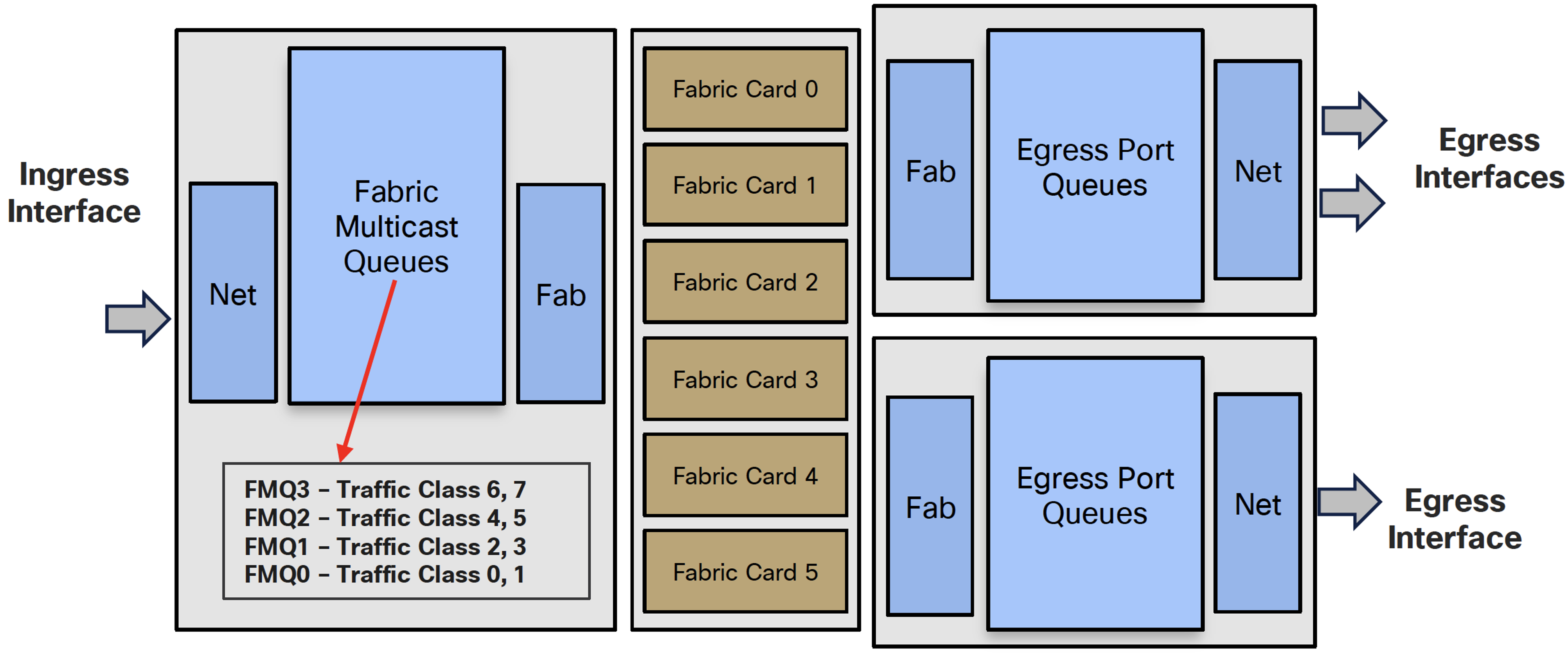
The solution to the above problem is the Fabric Multicast Queue (FMQ)
- Multicast packets are not classified in VOQs but in 4 Fabric Multicast Queues
- FMQ0 to FMQ2 will be Low Priority
- FMQ3 is treated as High priority in the Egress port queues
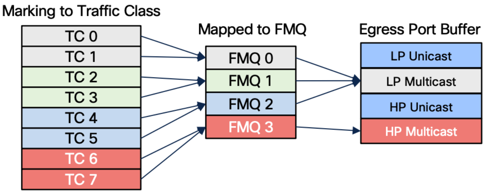
- Mapping is done in ingress between FMQ Traffic Class pairs
- Without policy-map, all multicast traffic is TC=0, which maps to FMQ0
- Can be influenced by QoS configuration
- But only via ingress classification with assignment to specific traffic-class
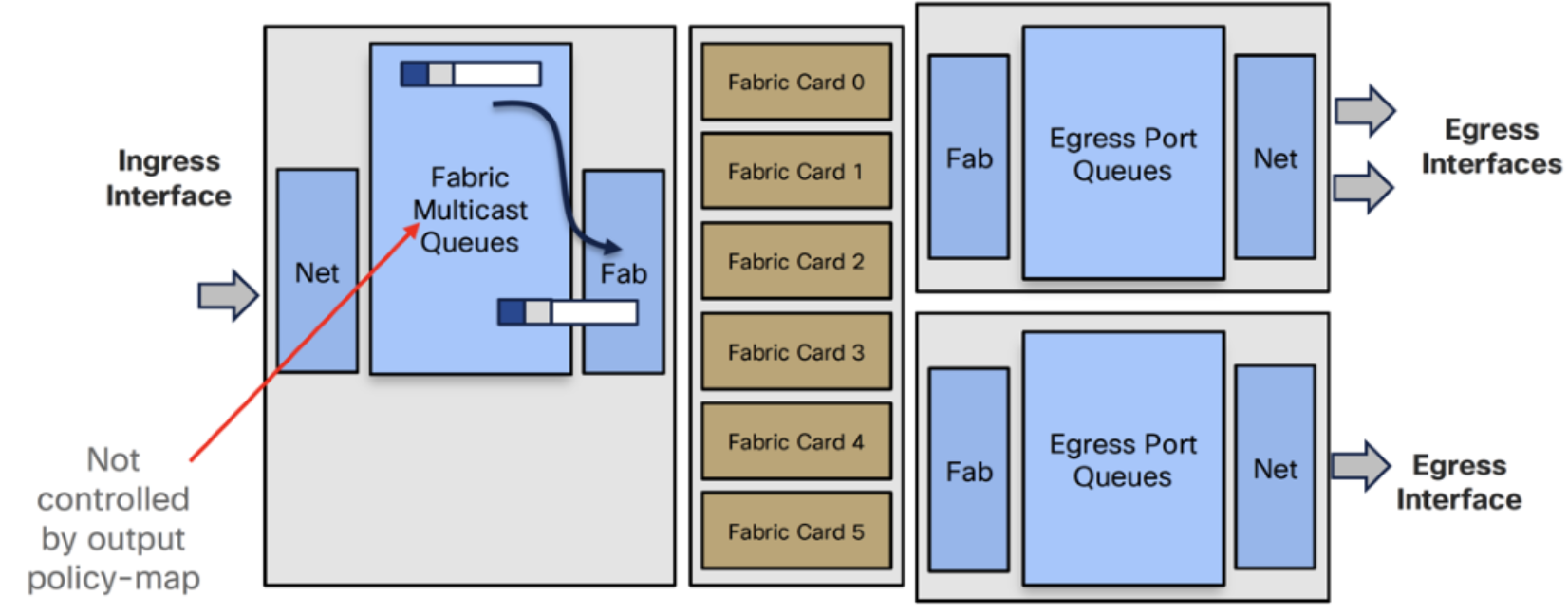
- Ingress policy-map but no queueing or shaping in egress policy-map
- Service-policy output will not count multicast packets
- Ingress Interface receives packet, applies input policy-map to move them to the right queue
- Then it makes forwarding decision and selects FMQ based on traffic class value
Life of a Multicast Packet
The following example will describe in detail how a multicast packet is being managed when it is received on the ingress port. A packet is received and the first thing that happens is the assignment of the traffic class.
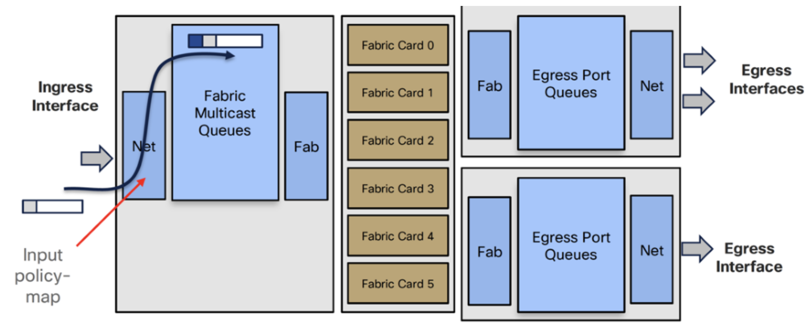
- Ingress Traffic Manager selects packet from an FMQ and sends it to Ingress Fab
- Ingress Fab splits packet into cells and load balances them across the fabric cards
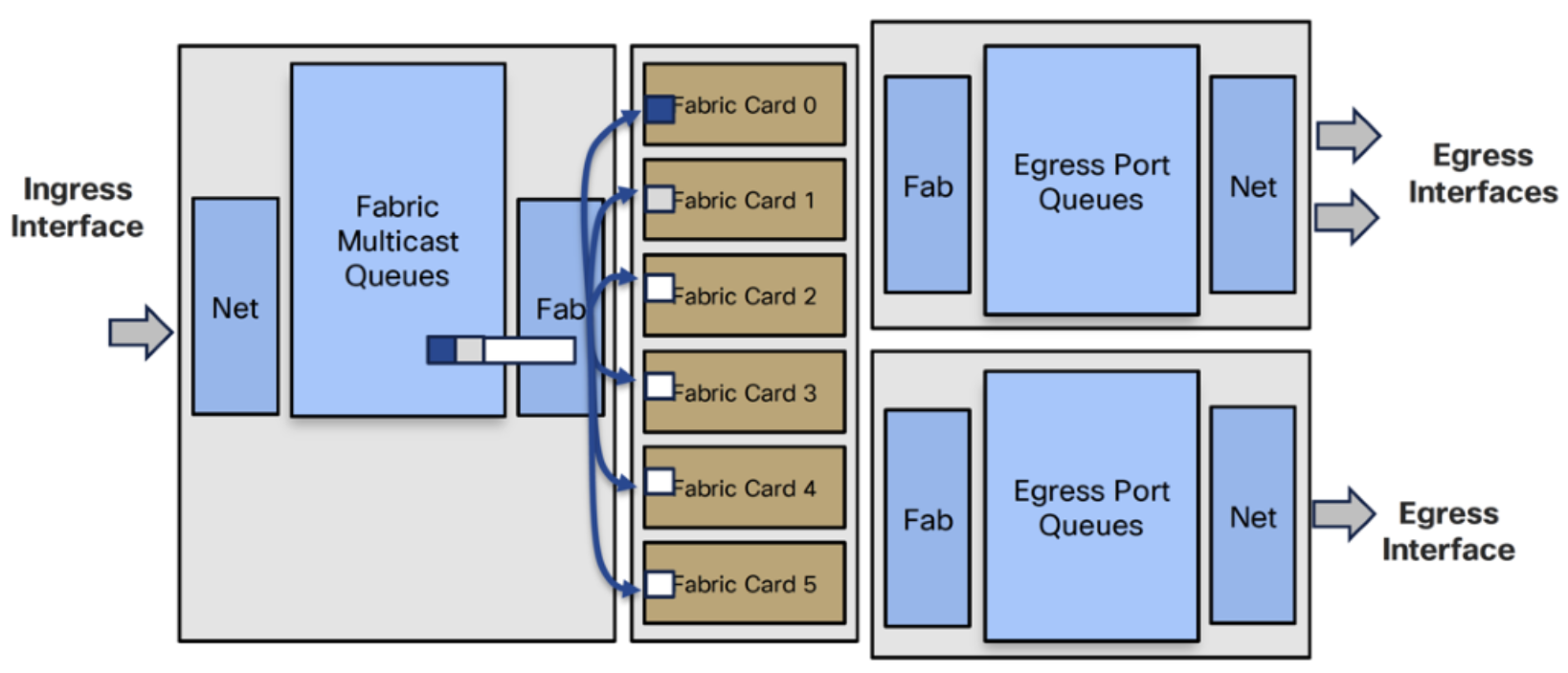
- Fabric cards replicate cells to each egress card
- Egress Fab reassembles and replicates to each interface’s egress queues
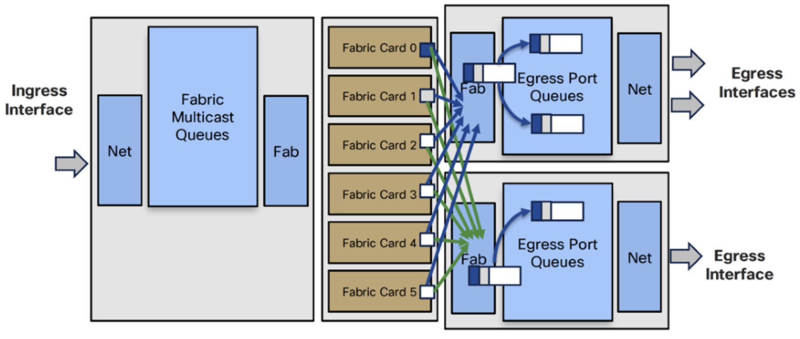
- Egress Traffic Manager selects packets from egress interface queues
- Egress Net transmits packets
- No ingress replication (one at the fabric, one at the egress NPU level)
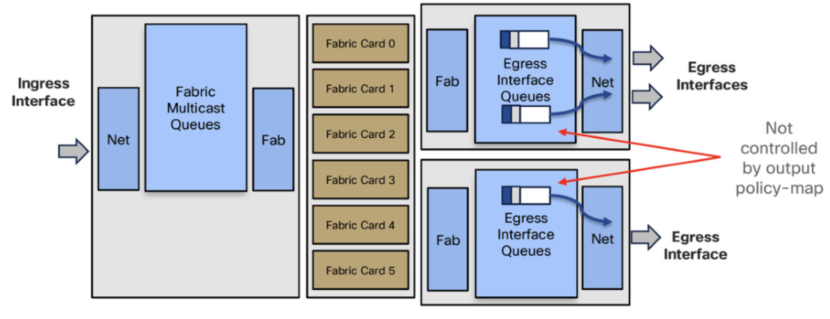
- Four shallow egress port queues per interfaces
- They hold the packets before they are put on the wire
In egress there is a pre-allocated buffer of 10 milliseconds, but this can be altered. The buffer can be reduced to 1 packet only, but this is not happening physically on the egress interface, it is happening for unicast traffic only on ingress. The multicast traffic will always take the remaining space of unicast traffic.
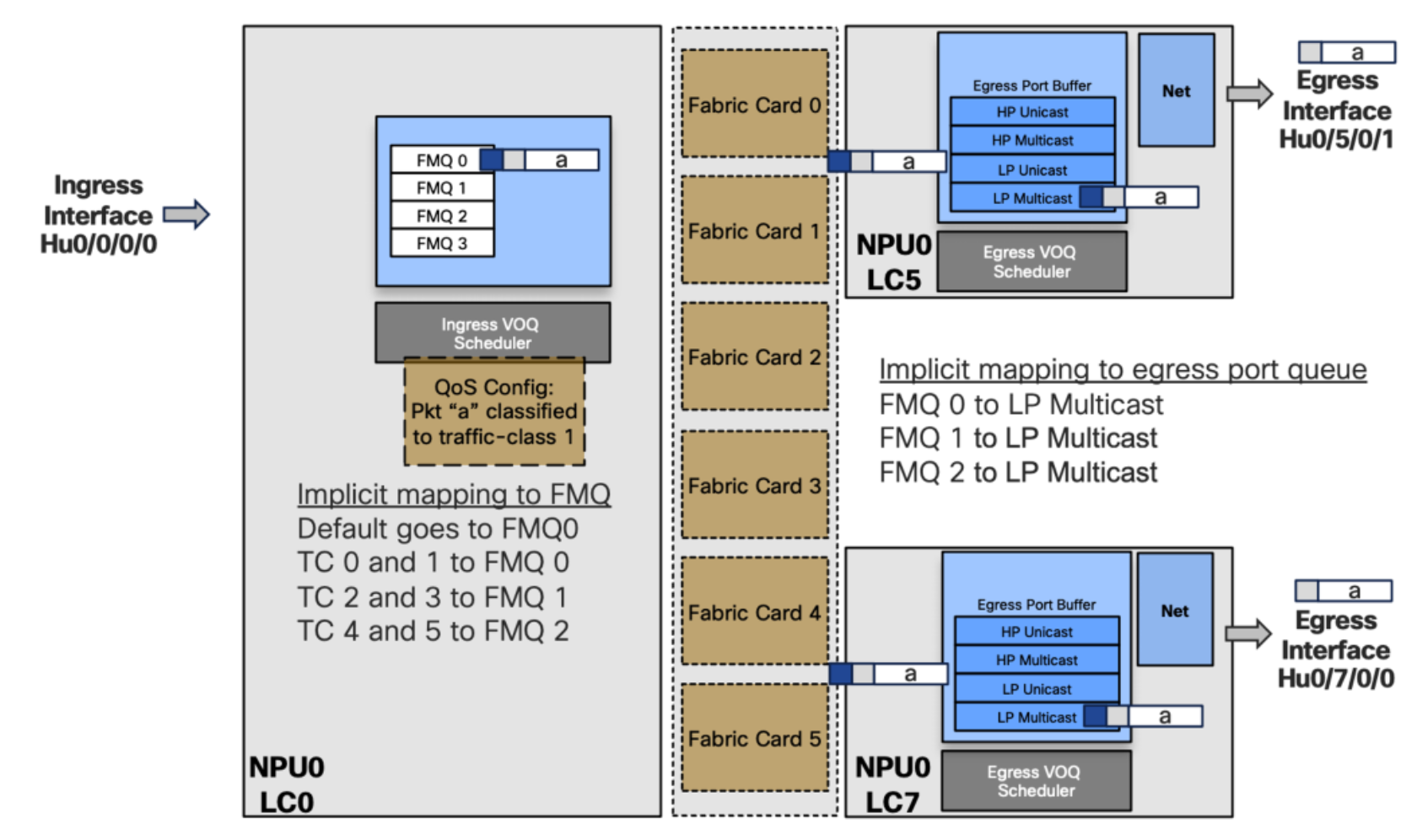
Test Case 1 – Traffic Class 1
Packet “a” is received on Hu0/0/0/0 and needs to be replicated to two egress ports:
- Hu0/5/0/1 (NPU 0 LC 5)
- Hu0/7/0/0 (NPU 0 LC 7)
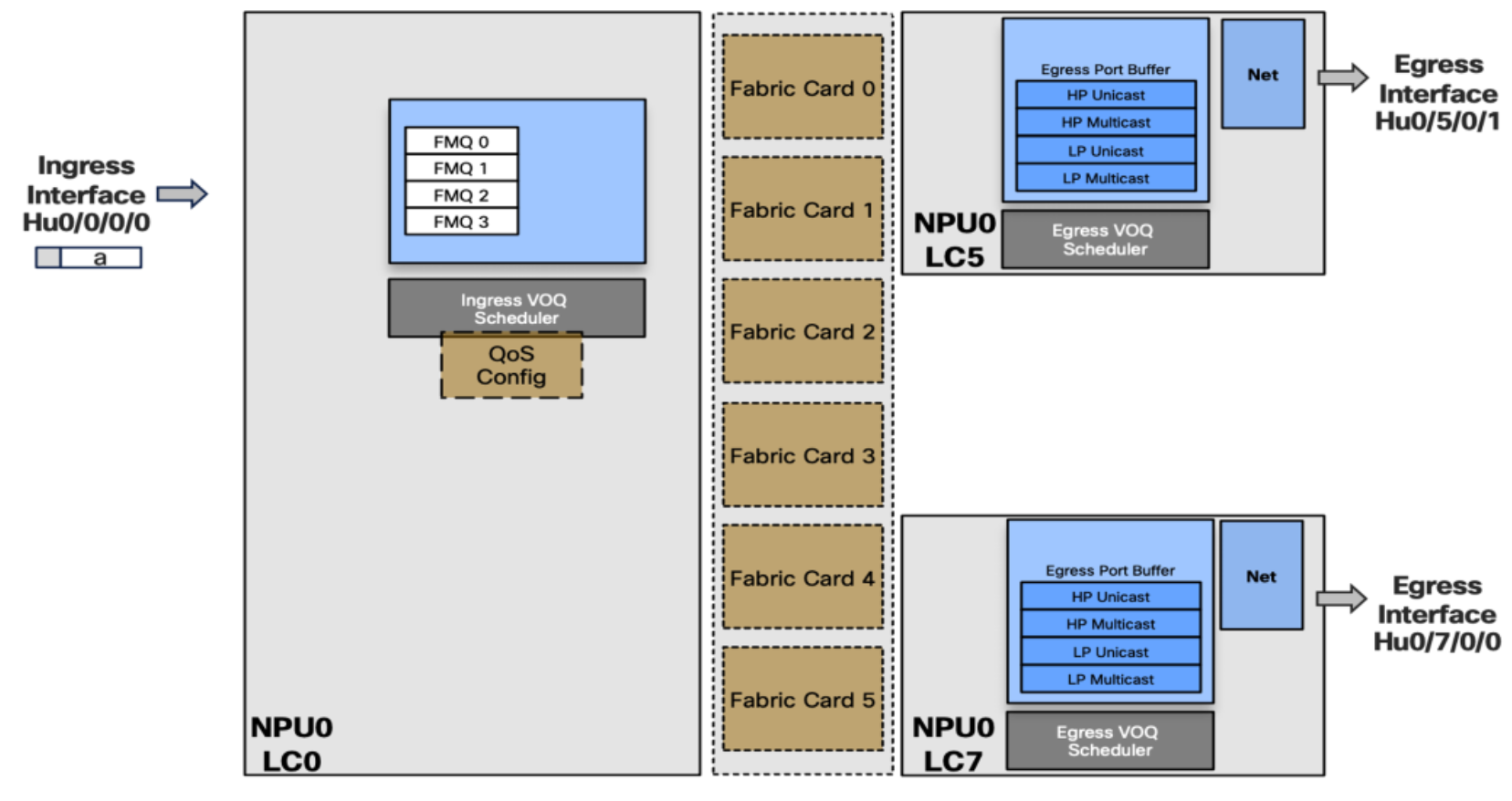
An input service policy is configured, classifies the multicast packet and marks it with TC 1. Automatically it will map TC 1 to FMQ 0 and transmit the packet to fabric where it will be replicated. A copy of the packet is received on the two egress pipelines. Since it is FMQ 0, the packet is stored in the low priority Multicast egress port buffer before being sent to the destination.
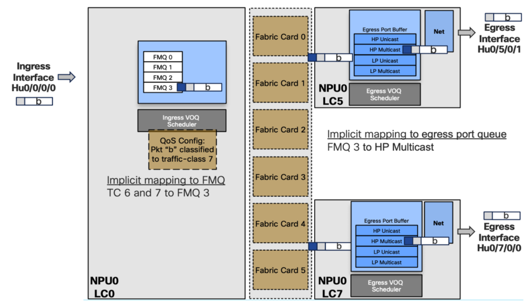
Test Case 2 – Traffic Class 6 or 7
The only difference now is that the traffic class is 6 or 7. The multicast packet will land on high priority Multicast on egress.
Multicast egress processing MCDB
- Re-assembled packets will be replicated on egress NPU based on MCID-DB information
- It is the second level of replication
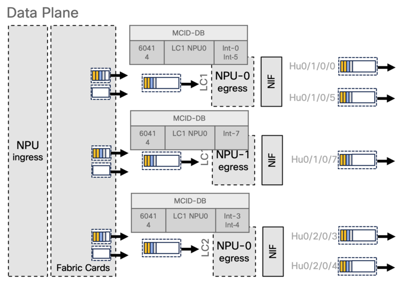
- Packet is passed to the fabric interface and split in cells
- Based on MCID-Mapping bitmap, the cells are replicated in the fabric to the NPUs where they are re-assembled by fabric interface
Unicast and Multicast
- Unicast scheduled (transmitted only after permission granted)
- Multicast unscheduled (only relying on back pressure mechanism to slow down)
- Egress port congestion possible: we need a tie-break
There is a possibility that the port will be congested when we have both unicast and multicast traffic. Unicast traffic waits for tokens to get transmitted while multicast traffic gets transmitted instantly. It is important to have differentiation between LP and HP. We need to know what kind of packet will go where. Packets without priority will be considered as unicast LP. Every packet marked as priority queue will be unicast HP. Also, locally generated traffic like BGP, IGMP, etc., will be treated as high priority unicast or multicast depending on the type of traffic. This the role of these 4 queues.
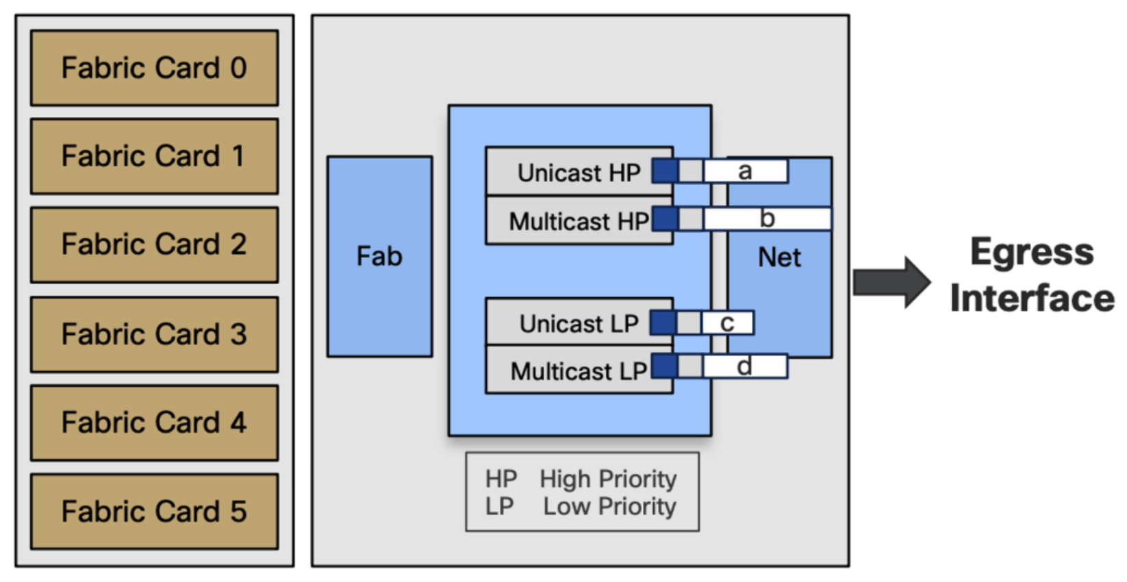
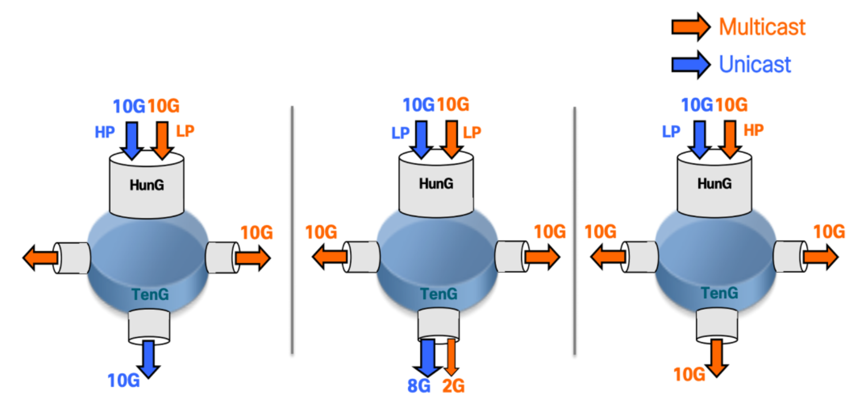
Tie-Break Case
- In case of egress interface congestion
- High priority will take full precedence over low priority
- If same priority (HP/HP or LP/LP), forwarding will be 80% ucast / 20% mcast
Future plan
A 2nd pass 3rd pass model where we will have packets received on the egress pipeline and recirculating to the ingress pipeline. This way the packet will go twice in the pipeline and buffered twice, and this is how it is done in ASR9K. The drawback is the cost, half of the packet per second being recirculated. Once this model gets adapted to multicast, it will be possible to classify the egress multicast but it is going to happen in the ingress side.
*Longest Prefix Match Database is a SRAM used to store IPv4 and IPv6 prefixes
Leave a Comment