
Tree-SID + COE
Tree-SID + COE
Tree-SID has been discussed as a multicast technology in IOS-XR. Our goal is to enhance that technology and expand its potential thats why we are optimizing it by using Crosswork Optimization Engine (COE).
There are 2 major challenges that we are trying to overcome:
- The lack of accurate and intuitive visibility into multicast deployments
- The effective alignment with the controller architecture
To solve the above we need a tool to discover and visualize the multicast policies the controller holds. In our case we can leverage COE and achieve operational agility with ease of visualization while providing rich automation benefits with a controller friendly architecture.
Cisco Crosswork is a suite of integrated applications that deliver adaptive network operations to achieve an autonomous, cloud-scale infrastructure using software-defined tools to manage multi-vendor and multi-domain networks. Cisco Crosswork Optimization Engine provides real-time network visualization and optimization capabilities, allowing operators to maximize network utility and increase service velocity.
Today we want to showcase the integration of Static and Dynamic Tree-SID with COE. The Crosswork team has invested time and effort to evolve Tree-SID into an automated solution while providing enhanced user experience. We have the option to visualize Tree-SID topology, sessions, policies, and more in line with an automated Multicast solution. In the rest of this article, we will go over screenshots from the COE dashboard and use them to visualize the TreeSID SR Policies on the routers.
Furthermore, there is the need of validating tree disjointness for video distribution:
- SR-PCE allows to compute and deploy it (automatically).
- COE allows to visualize, and ‘prove’ trees are disjoint.
Topology
The topology that will be used is shown below.
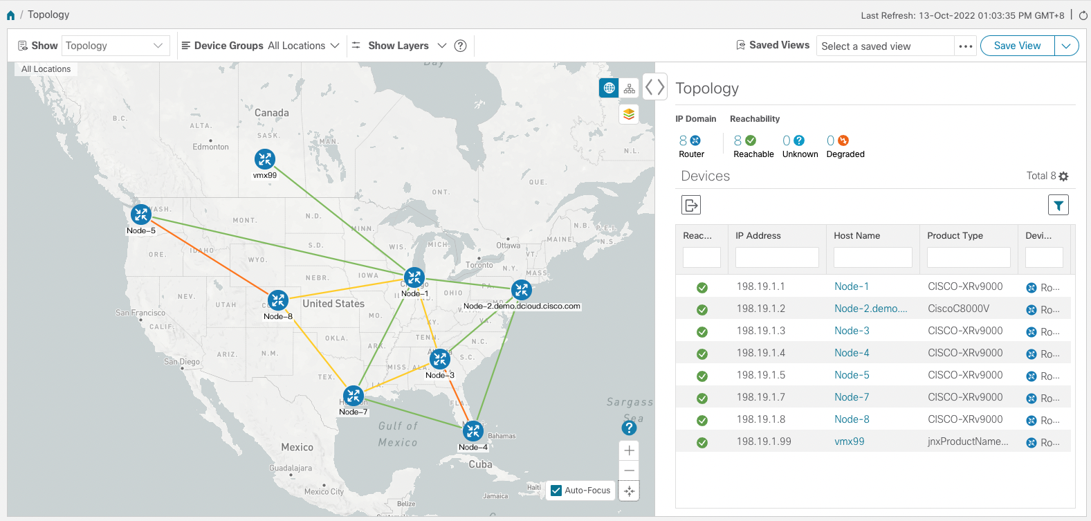
We can see all the nodes that will be used in the following examples. The nodes are xrv9k devices and they will be used for both Static and Dynamic Tree-SID.
Common Configuration
SR-PCE Configuration
The PCE holds PCEP sessions with all the routers in the topology. We can verify that by running the following command:
Command:
show pce ipv4 peer
Output:
PCE's peer database:
--------------------
Peer address: 198.19.1.1
  State: Up
  Capabilities: Stateful, Segment-Routing, Update, Instantiation, SRv6

Peer address: 198.19.1.3
  State: Up
  Capabilities: Stateful, Segment-Routing, Update, Instantiation, SRv6

Peer address: 198.19.1.4
  State: Up
  Capabilities: Stateful, Segment-Routing, Update, Instantiation, SRv6

Peer address: 198.19.1.5
  State: Up
  Capabilities: Stateful, Segment-Routing, Update, Instantiation, SRv6

Peer address: 198.19.1.7
  State: Up
  Capabilities: Stateful, Segment-Routing, Update, Instantiation, SRv6

Peer address: 198.19.1.8
  State: Up
  Capabilities: Stateful, Segment-Routing, Update, Instantiation, SRv6
Static Tree-SID + COE
In our topology, there are two static Tree-SID policies configured,
- sr_p2mp_root_198.19.1.5_static_c40
- sr_p2mp_root_198.19.1.5_static_c41
Both Tree-SID policies are rooted at Node-5 but are optimized for different metric (TE and IGP metric respectively). Tree-SID policies also support the use of link affinity constraints, although this is not configured in the current setup.
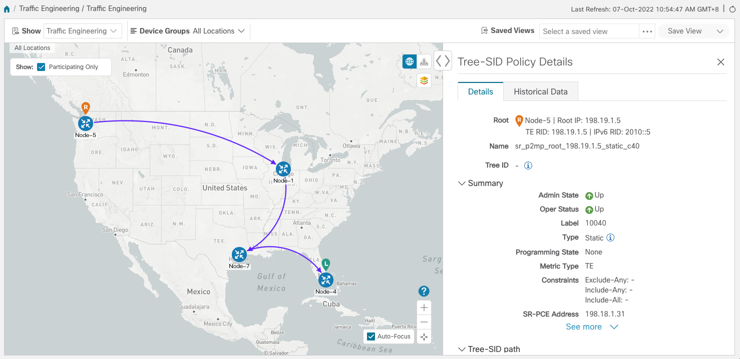
The following screenshots show one of the static Tree-SID polices as rendered by the Crosswork Optimization Engine. All essential information on the Tree-SID policy including the root node, name, tree-ID, admin and operational Status, SR label, type (static/dynamic), metric type, affinity constraints and path details are shown. This allows the operator to view all essential information pertaining to the Tree-SID policy at a glance.
Static Tree-SID policy summary:
Static Tree-SID policy path:
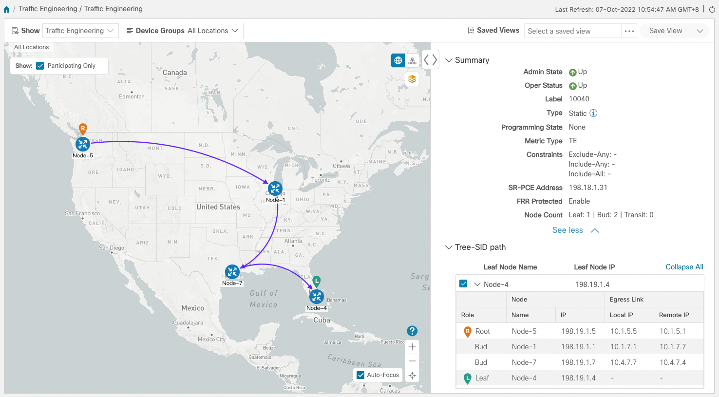
We can see from the path topology that the Tree-SID policy is rooted at Node-5. Bud nodes are Node-1, Node-7 and the Leaf node is Node-4.
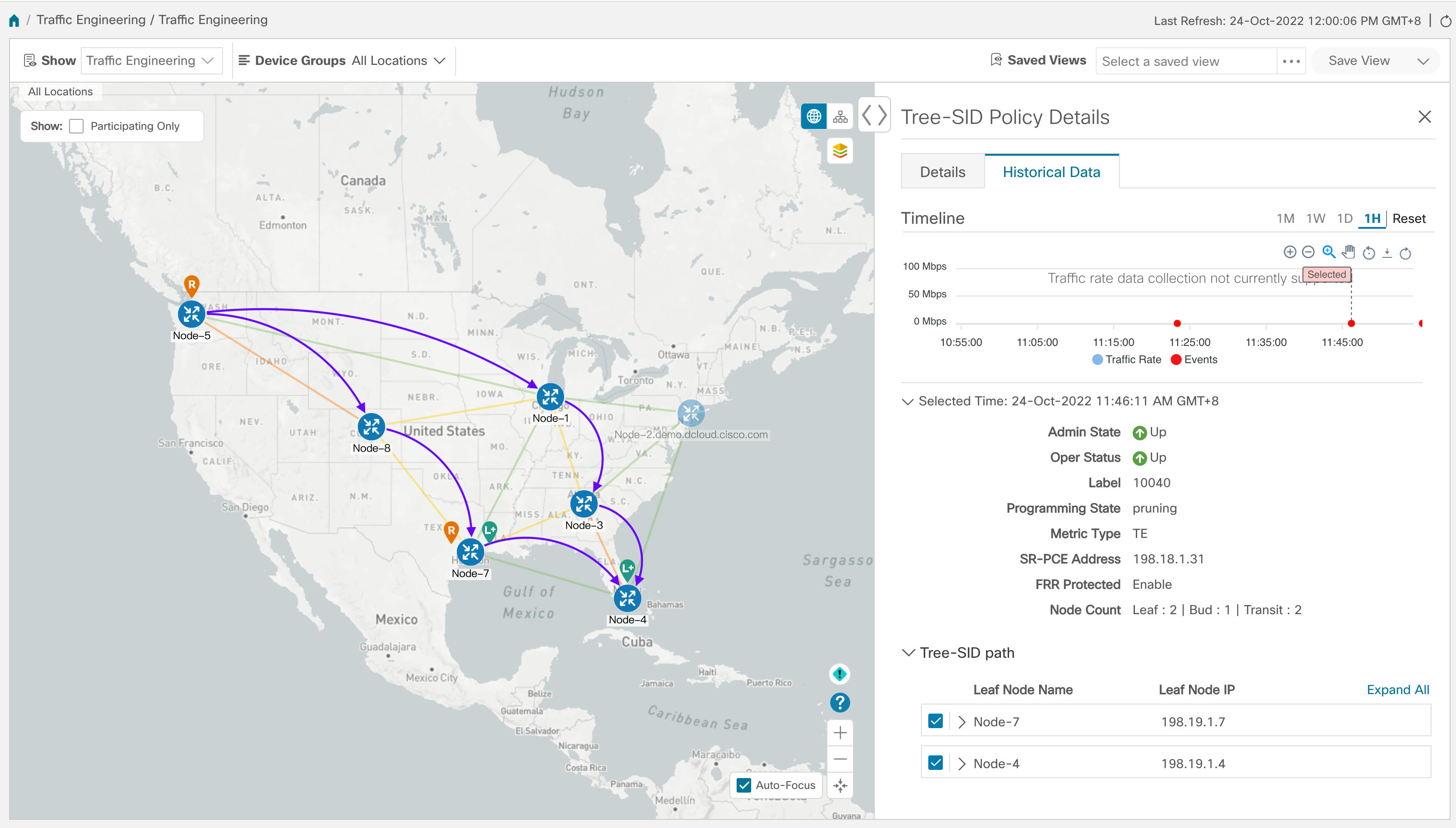
In addition, COE maintains an event history of the Tree-SID policy. The operator may use the COE UI to learn about past events such as admin and operational state changes, and changes in the Tree-SID SR policy paths. When an event is selected, details of the Tree-SID Policy Path at that time will be shown.
Static Tree-SID policy events:
Note: For Static Tree-SID only the PCE configuration is required to initiate the Tree-SID Policy on the control plane. The rest of the configuration are provided for completeness.
Configurations
PCE config:
pce
 address ipv4 198.19.1.201
 segment-routing
  traffic-eng
   p2mp
    endpoint-set sr_p2mp_c40_ep
     ipv4 198.19.1.1
     ipv4 198.19.1.4
     ipv4 198.19.1.7
    !
    endpoint-set sr_p2mp_c41_ep
     ipv4 198.19.1.1
     ipv4 198.19.1.3
     ipv4 198.19.1.4
    !
    policy sr_p2mp_root_198.19.1.5_static_c40
     source ipv4 198.19.1.5
     color 40 endpoint-set sr_p2mp_c40_ep
     treesid mpls 10040
     candidate-paths
      preference 100
       dynamic
        metric
         type te
        !
    policy sr_p2mp_root_198.19.1.5_static_c41
     source ipv4 198.19.1.5
     color 41 endpoint-set sr_p2mp_c41_ep
     treesid mpls 10041
     candidate-paths
      preference 100
       dynamic
        metric
         type igp
Root config:
vrf L3VPN_NM-SRTE-ODN-40
 address-family ipv4 unicast
  import route-target
   65000:40
  !
  export route-target
   65000:40
!
vrf L3VPN_NM-SRTE-ODN-41
 address-family ipv4 unicast
  import route-target
   65000:41
  !
  export route-target
   65000:41
  !
 !
!
interface Loopback40
 description T-SDN interface
 vrf L3VPN_NM-SRTE-ODN-40
 ipv4 address 10.40.5.1 255.255.255.252
!
interface Loopback41
 description T-SDN interface
 vrf L3VPN_NM-SRTE-ODN-41
 ipv4 address 10.41.5.1 255.255.255.252
!
route-policy sr-p2mp-core-tree
  set core-tree sr-p2mp
end-policy
!
multicast-routing
 address-family ipv4
  interface Loopback0
   enable
  !
  mdt source Loopback0
 !
 vrf L3VPN_NM-SRTE-ODN-40
  address-family ipv4
   mdt source Loopback0
   interface all enable
   mdt static segment-routing
!
 vrf L3VPN_NM-SRTE-ODN-41
  address-family ipv4
   mdt source Loopback0
   interface all enable
   mdt static segment-routing
  !
 !
!
router pim
 address-family ipv4
  interface Loopback0
   enable
  !
 !
 vrf L3VPN_NM-SRTE-ODN-40
  address-family ipv4
   rpf topology route-policy sr-p2mp-core-tree
   sr-p2mp-policy sr_p2mp_root_198.19.1.5_static_c40
    static-group 232.0.0.40 10.40.5.1
   !
  !
 !
 vrf L3VPN_NM-SRTE-ODN-41
  address-family ipv4
   rpf topology route-policy sr-p2mp-core-tree
   sr-p2mp-policy sr_p2mp_root_198.19.1.5_static_c41
    static-group 232.0.0.41 10.41.5.1
Leaf config:
vrf L3VPN_NM-SRTE-ODN-40
 address-family ipv4 unicast
  import route-target
   65000:40
  !
  export route-target
   65000:40
!
vrf L3VPN_NM-SRTE-ODN-41
 address-family ipv4 unicast
  import route-target
   65000:41
  !
  export route-target
   65000:41
  !
 !
!
interface Loopback40
 description T-SDN interface
 vrf L3VPN_NM-SRTE-ODN-40
 ipv4 address 10.40.4.1 255.255.255.252
!
interface Loopback41
 description T-SDN interface
 vrf L3VPN_NM-SRTE-ODN-41
 ipv4 address 10.41.4.1 255.255.255.252
!
route-policy sr-p2mp-core-tree
  set core-tree sr-p2mp
end-policy
!
multicast-routing
 address-family ipv4
  interface Loopback0
   enable
  !
  mdt source Loopback0
 !
 vrf L3VPN_NM-SRTE-ODN-40
  address-family ipv4
   mdt source Loopback0
   interface all enable
   static sr-policy sr_p2mp_root_198.19.1.5_static_c40
   mdt static segment-routing
  !
 !
 vrf L3VPN_NM-SRTE-ODN-41
  address-family ipv4
   mdt source Loopback0
   interface all enable
   static sr-policy sr_p2mp_root_198.19.1.5_static_c41
   mdt static segment-routing
  !
 !
!
router igmp
 vrf L3VPN_NM-SRTE-ODN-40
  interface Loopback40
   join-group 232.0.0.40 10.40.5.1
  !
 !
 vrf L3VPN_NM-SRTE-ODN-41
  interface Loopback41
   join-group 232.0.0.41 10.41.5.1
  !
 !
!
router pim
 address-family ipv4
  interface Loopback0
   enable
  !
 !
 vrf L3VPN_NM-SRTE-ODN-40
  address-family ipv4
   rpf topology route-policy sr-p2mp-core-tree
  !
 !
 vrf L3VPN_NM-SRTE-ODN-41
  address-family ipv4
   rpf topology route-policy sr-p2mp-core-tree
  !
 !
Show Outputs
PCE
The control plane has already been established and we can see the LSPs that are rooted at Node-5, Root Node (198.19.1.5) with the corresponding Tree-IDs.
Command:
show pce lsp p2mp
Output:
Tree: sr_p2mp_root_198.19.1.5_static_c40, Root: 198.19.1.5
 PCC: 198.19.1.5
 Label:    10040     Operational: up  Admin: up
 Local LFA FRR: Enabled
 Metric Type: TE
 Transition count: 1
 Uptime: 00:16:31 (since Fri Oct 07 02:36:42 UTC 2022)
 Destinations: 198.19.1.1, 198.19.1.4, 198.19.1.7
 Nodes:
  Node[0]: 198.19.1.5 (Node-5)
   Role: Ingress
   Hops:
    Incoming: 10040 CC-ID: 1
    Outgoing: 10040 CC-ID: 1 (198.19.1.1!) [Node-1]
  Node[1]: 198.19.1.1 (Node-1)
   Role: Bud-Node
   Hops:
    Incoming: 10040 CC-ID: 2
    Outgoing: 10040 CC-ID: 2 (198.19.1.7!) [Node-7]
  Node[2]: 198.19.1.7 (Node-7)
   Role: Bud-Node
   Hops:
    Incoming: 10040 CC-ID: 4
    Outgoing: 10040 CC-ID: 4 (198.19.1.4!) [Node-4]
  Node[3]: 198.19.1.4 (Node-4)
   Role: Egress
   Hops:
    Incoming: 10040 CC-ID: 5
Root
Now lets check the configuration of that specific VRF (L3VPN_NM-SRTE-ODN-40). The multicast routing for IPv4 and the bgp auto-discovery are enabled and we will use mdt static segment routing.
Command:
show run multicast-routing vrf L3VPN_NM-SRTE-ODN-40
Output:
multicast-routing
 vrf L3VPN_NM-SRTE-ODN-40
  address-family ipv4
   mdt source Loopback0
   interface all enable
   mdt static segment-routing
  !
 !
!
Dynamic Tree-SID + COE
The topology that will be used is shown below.
In our topology, there is a dynamic Tree-SID policy configured. The following shows a screenshot of the dynamic Tree-SID policy as rendered by the Crosswork Optimization Engine.
Dynamic Tree-SID policy summary:
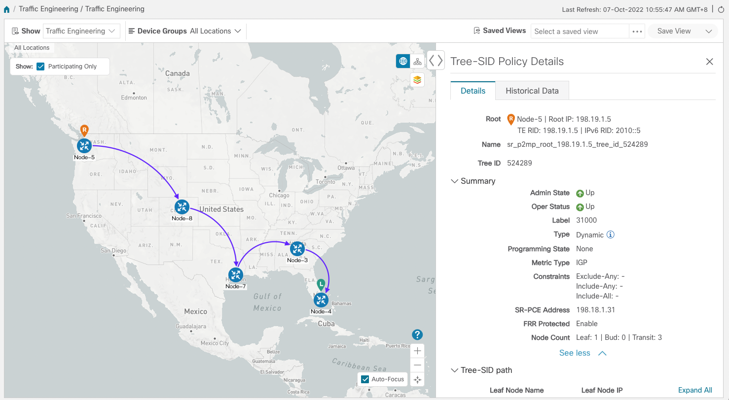
Dynamic Tree-SID policy path:
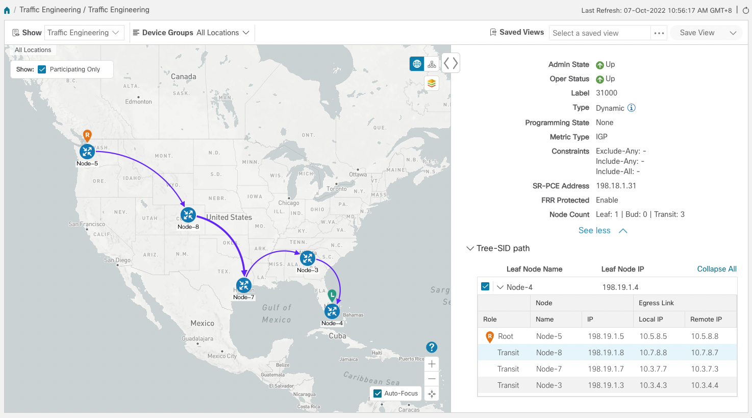
We can see from the path topology that the Root is Node-5, Transit nodes are Node-8, Node-7, Node-3 and the Leaf node is Node-4.
Note: SR Policy events history is currently not available for Dynamic Tree-SID policies.
Configurations
On the PCE, we require a label-range for allocation for Dynamic Tree-SID policies. The PCE will also allocate a dynamic Tree-ID value which is not present for static Tree SID policies.
PCE config
router bgp 65000
 address-family ipv4 mvpn
 !
 neighbor-group AS65000-RRC-services-group
  address-family ipv4 mvpn
   route-reflector-client
 !
pce
 segment-routing
  traffic-eng
   p2mp
    label-range min 30000 max 31000
    fast-reroute lfa
    multipath-disable
Root config
vrf L3VPN_NM-MVPN-80
 address-family ipv4 unicast
  import route-target
   65000:80
  !
  export route-target
   65000:80
  !
!
router bgp 65000
 address-family ipv4 mvpn
 !
 neighbor-group RR-services-group
   address-family ipv4 mvpn
!
 vrf L3VPN_NM-MVPN-80
  rd 65000:80
  address-family ipv4 unicast
   redistribute connected
  !
  address-family ipv4 mvpn
  !
!
segment-routing
 traffic-eng
 on-demand color 80
   dynamic
    pcep
    !
    metric
     type igp
!
route-policy L3VPN_NM-MVPN-80
  if destination in (232.0.0.80) then
    set on-demand-color 80
    pass
  endif
end-policy
!
interface Loopback80
 description T-SDN interface
 vrf L3VPN_NM-MVPN-80
 ipv4 address 10.80.5.1 255.255.255.252
!
multicast-routing
 vrf L3VPN_NM-MVPN-80
  address-family ipv4
   interface all enable
   bgp auto-discovery segment-routing
   !
   mdt default segment-routing mpls color 80
   mdt data segment-routing mpls 2 color 80
  !
 !
Leaf config
vrf L3VPN_NM-MVPN-80
 address-family ipv4 unicast
  import route-target
   65000:80
  !
  export route-target
   65000:80
  !
 !
!
router bgp 65000
 address-family ipv4 mvpn
!
 neighbor-group RR-services-group
  address-family ipv4 mvpn
 !
 vrf L3VPN_NM-MVPN-80
  rd 65000:80
  address-family ipv4 unicast
   redistribute connected
  !
  address-family ipv4 mvpn
  !
 !
!
interface Loopback80
 description T-SDN interface
 vrf L3VPN_NM-MVPN-80
 ipv4 address 10.80.4.1 255.255.255.252
!
multicast-routing
 vrf L3VPN_NM-MVPN-80
  address-family ipv4
   interface all enable
   bgp auto-discovery segment-routing
   !
   mdt default segment-routing mpls color 80
  !
 !
The transit nodes do not hold any Tree-SID specific configuration.
Show outputs
PCE
Command:
show pce lsp p2mp root ipv4 198.19.1.5 | include Tree
Output:
Tree: sr_p2mp_root_198.19.1.5_tree_id_524289, Root: 198.19.1.5 ID: 524289
The next output shows the Tree stucture including the Root (Ingress), the Transit nodes and the leaves (Egress) with the corresponding label ID (31000) of the Tree. The PCE will pick a label within the provided range to be allocated for the dynamic Tree-SID policy. For Dynamic Tree-SID policies, a dynamic Tree-ID value will be allocated by the SR-PCE.
Command:
show pce lsp p2mp root ipv4 198.19.1.5
Output:
Tree: sr_p2mp_root_198.19.1.5_tree_id_524289, Root: 198.19.1.5 ID: 524289
 PCC: 198.19.1.5
 Label:    31000     Operational: up  Admin: up
 Local LFA FRR: Enabled
 Metric Type: IGP
 Transition count: 1
 Uptime: 06:10:10 (since Mon Oct 03 02:06:06 UTC 2022)
 Destinations: 198.19.1.4
 Nodes:
  Node[0]: 198.19.1.3 (Node-3)
   Role: Transit
   Hops:
    Incoming: 31000 CC-ID: 1
    Outgoing: 31000 CC-ID: 1 (198.19.1.4!) [Node-4]
  Node[1]: 198.19.1.7 (Node-7)
   Role: Transit
   Hops:
    Incoming: 31000 CC-ID: 2
    Outgoing: 31000 CC-ID: 2 (198.19.1.3!) [Node-3]
  Node[2]: 198.19.1.8 (Node-8)
   Role: Transit
   Hops:
    Incoming: 31000 CC-ID: 3
    Outgoing: 31000 CC-ID: 3 (198.19.1.7!) [Node-7]
  Node[3]: 198.19.1.5 (Node-5)
   Role: Ingress
   Hops:
    Incoming: 31000 CC-ID: 4
    Outgoing: 31000 CC-ID: 4 (198.19.1.8!) [Node-8]
  Node[4]: 198.19.1.4 (Node-4)
   Role: Egress
   Hops:
    Incoming: 31000 CC-ID: 5
Root
From the root node we can get information such as VRFs, traffic-eng configurations, mvpn and segment-routing configurations.
Command:
show vrf L3VPN_NM-MVPN-80
Output:
VRF                  RD                  RT                         AFI   SAFI
L3VPN_NM-MVPN-80     65000:80
                                         import  65000:80            IPV4  Unicast
                                         export  65000:80            IPV4  Unicast
Now lets check the configuration of that specific VRF. The multicast routing for IPv4 and the bgp auto-discovery are enabled, we will use segment routing P2MP and we will allow default MDT based on P2MP SR policy.
Command:
show run multicast-routing vrf L3VPN_NM-MVPN-80
Output:
multicast-routing
 vrf L3VPN_NM-MVPN-80
  address-family ipv4
   interface all enable
   bgp auto-discovery segment-routing
   !
   mdt default segment-routing mpls color 80
   mdt data segment-routing mpls 2 color 80
  !
 !
!
There is one important thing to notice in the following command output which is the metric type IGP. Any Tree that is going to be built as part of the default or data MDT is going to be built based on that metric.
Command:
show run segment-routing traffic-eng on-demand color 80
Output:
segment-routing
 traffic-eng
  on-demand color 80
   dynamic
    pcep
    !
    metric
     type igp
    !
   !
  !
 !
!
Below we can see the Route Type 1s for the PEs. Node-5 (198.19.1.5) is the Ingress PE and Node-4 (198.19.1.4) is the Egress PE.
Command:
show bgp vrf L3VPN_NM-MVPN-80 ipv4 mvpn
Output:
BGP VRF L3VPN_NM-MVPN-80, state: Active
BGP Route Distinguisher: 65000:80
VRF ID: 0x60000003
BGP router identifier 198.19.1.5, local AS number 65000
Non-stop routing is enabled
BGP table state: Active
Table ID: 0x0   RD version: 5
BGP main routing table version 5
BGP NSR Initial initsync version 2 (Reached)
BGP NSR/ISSU Sync-Group versions 0/0

Status codes: s suppressed, d damped, h history, * valid, > best
              i - internal, r RIB-failure, S stale, N Nexthop-discard
Origin codes: i - IGP, e - EGP, ? - incomplete
   Network            Next Hop            Metric LocPrf Weight Path
Route Distinguisher: 65000:80 (default for vrf L3VPN_NM-MVPN-80)
*>i[1][198.19.1.4]/40 198.19.1.4                    100      0 i
*> [1][198.19.1.5]/40 0.0.0.0                                0 i

Processed 2 prefixes, 2 paths
The following is the default MDT or I-PMSI. It has 1 member which is root Node-4 (198.19.1.4) and there is a Tree with ID 524289.
Command:
show mvpn vrf L3VPN_NM-MVPN-80 database segment-routing
Output:
* - LFA protected MDT
Core Type      Core            Tree Core        State  On-demand
              Source           Information             Color

Default        198.19.1.5       524289 (0x80001)    Up 80
   I-PMSI Leg:      198.19.1.4
Part              0.0.0.0            0 (0x00000)  Down 80
Control           0.0.0.0            0 (0x00000)  Down 80
Transit Node 3
Below we can see the P2MP SR policy on all transit nodes that are part of the Tree-SID topology.
Command:
show segment-routing traffic-eng p2mp policy root ipv4 198.19.1.5
Output:
SR-TE P2MP policy database:
----------------------
! - Replications with Fast Re-route, * - Stale dynamic policies/endpoints

Policy: sr_p2mp_root_198.19.1.5_tree_id_524289  LSM-ID: 0x40002
 Root: 198.19.1.5, ID: 524289
 Role: Transit
 Replication:
  Incoming label: 31000 CC-ID: 1
  Interface: None [198.19.1.4!]  Outgoing label: 31000 CC-ID: 1
Transit Node 7
Command:
show segment-routing traffic-eng p2mp policy root ipv4 198.19.1.5
Output:
SR-TE P2MP policy database:
----------------------
! - Replications with Fast Re-route, * - Stale dynamic policies/endpoints

Policy: sr_p2mp_root_198.19.1.5_tree_id_524289  LSM-ID: 0x40003
 Root: 198.19.1.5, ID: 524289
 Role: Transit
 Replication:
  Incoming label: 31000 CC-ID: 2
  Interface: None [198.19.1.3!]  Outgoing label: 31000 CC-ID: 2
Transit Node 8
Command:
show segment-routing traffic-eng p2mp policy root ipv4 198.19.1.5
Output:
SR-TE P2MP policy database:
----------------------
! - Replications with Fast Re-route, * - Stale dynamic policies/endpoints

Policy: sr_p2mp_root_198.19.1.5_tree_id_524289  LSM-ID: 0x40003
 Root: 198.19.1.5, ID: 524289
 Role: Transit
 Replication:
  Incoming label: 31000 CC-ID: 3
  Interface: None [198.19.1.7!]  Outgoing label: 31000 CC-ID: 3
This concludes the configuration and show command outputs from the IOS-XR devices, as well as showcasing Crosswork Optimization Engine’s Tree-SID visualization capabilities. We hope you find this article informative.
Leave a Comment