Introducing NCS 57B1 Routers
Introduction
With IOS XR 7.3.1, we introduced multiple software features (https://xrdocs.io/ncs5500/tutorials/iosxr-731-innovations/) but new hardware are also launched with this release. Among them, the NCS 57B1 series.
These two new routers are the NCS57B1-6D24 and NCS57B1-5DSE, both 1RU systems with a mix of 100G and 400G ports and powered by a Broadcom Jericho2 NPU.
They can be used in multiple places in the network, like aggregation (100G to 400G), 5G (class-C capable), internet peering, core, …
If it can offer 10G breakout through QSA and break-out cables, this router is optimized for 100G and 400G interfaces.
Videos
.
And since you didn’t ask for it, the unboxing :))
.
Naming logic
To understand where the product names NCS57B1-6D24 and -5DSE come from:

Product description
You can find the datasheet on Cisco’s website:
https://www.cisco.com/c/en/us/products/collateral/routers/network-convergence-system-5500-series/datasheet-c78-744698.html
It contains a lot of details on the part numbers, licenses, standards compliance, and much more.
We differentiate:
- the “base” system (Jericho2 without eTCAM) offering 24x 100G and 6x 400G ports: NCS57B1-6D24

- the “scale” system (Jericho2 with OP2 eTCAM) offering 24x 100G and 5x 400G ports: NCS57B1-5DSE

The difference between the two versions is simply the presence of an eTCAM and for the system equipped with this additional resource, we have one port QSFP-DD 400G left.
This eTCAM is connected to the fabric ports for the routes and classifiers, but we are using “NIF” ports for the statistics, hence the impact on the 400G port density.
Hardware

From the back, you find:
- two power supply modules (AC or DC) 2kW offering 1+1 redundancy (PSU2KW-ACPI or PSU2KW-DCPI). Note we don’t support the mix of AC and DC, and the cooling is only front-to-back today.
- 6 fan trays (NC57-B1-FAN1-FW) offering 5+1 redundancy.

In the front, we have 100G ports (QDD cages, designed for high power optics) on the left part and 400G (QDD too) on the right. These cages will permit the use of 100G ZR optics in the upper row (the exact amount of optics is still under validation and will be updated later) and 400G ZR/ZR+ in all the ports on the right.


Finally, on the right end, we have the timing ports and management ports.
- RJ45 for TOD
- SMB connectors (1PPS and 10Mhz clock)
- One antenna port for GPS
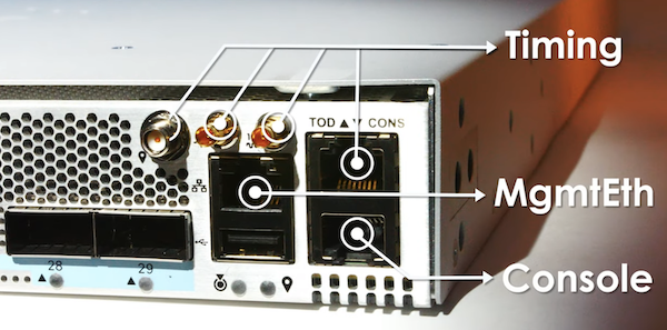
The NCS 57B1 routers are Class-C timing capable, on all ports.
NPU
These routers are “system on a chip” or SoC. All ports are connected to a single chipset (via reverse gear boxes, we will describe it further, later with the block diagram). That makes the design very simple and efficient in term of latency, performance and power consumption.
At the heart, we have the Broadcom Jericho 2 NPU. It offers 4.8 Tbps and 2BPPS of forwarding capacity.
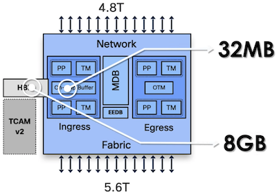
Like it’s predecessors using in NCS 5500 platforms, it’s a VOQ-only forwarding architecture with ingress hybrid packet buffering. Hybrid here means the packets can be stored in a 32MB on-chip memory or in an 8GB external HBM in case of queue congestion.
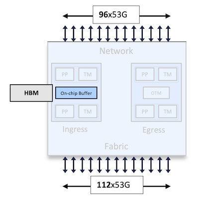
The NPU uses 50Gbps (a bit more than 53 with encoding and headers) SERDES to connect to the Reverse Gear Boxes:
Block Diagrams
NCS57B1-6D24 and NCS57B1-5DSE:
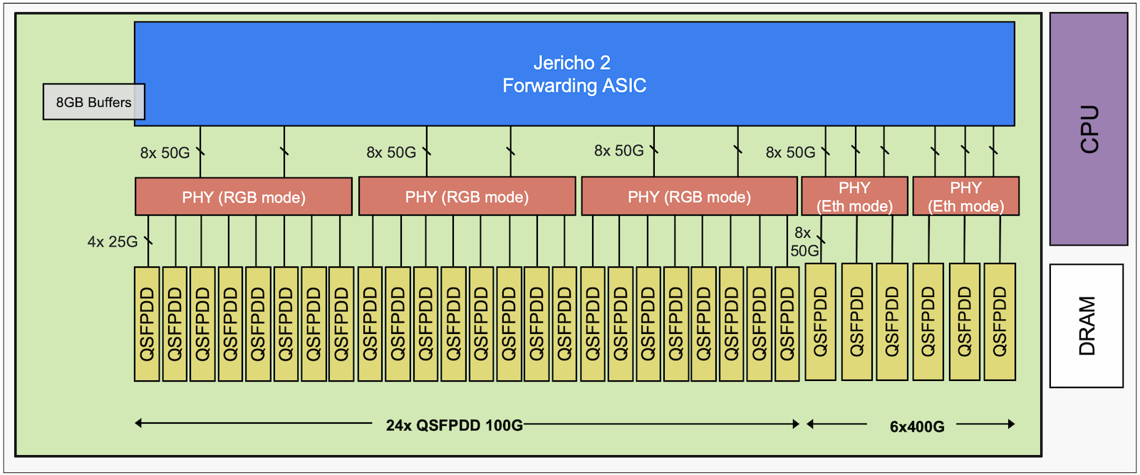
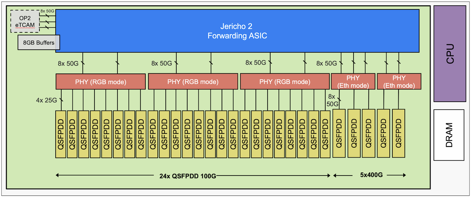
From an architecture point of view, very few differences between the two platforms. Some interfaces links being used to connect to the statistic part of the OP2 eTCAM, hence the different 400G port density.
Jericho 2 ASIC is connected to PHY chipsets operated in reverse gear boxes to connect to the 100G interfaces or switching mode to connect to the 400G interfaces.
Software
The NCS571B are both introduced with IOS XR 7.3.1, that’s the minimum release to support them.
Since it’s a standalone platform, it operates by default in “Native Mode”, no configuration is required to enable that mode.
Note: this system is using the newest version of IOS XR named XR7. XR7 is the latest evolution of the operating system and from feature and scale is similar to XR64bit used in other NCS5500 product. The main noticeable difference will be in the upgrade process based on Golden ISO images and the “install replace” approach instead of the “install add / install activate” methodology.
Take a look at the setup guide for mode details.
Ports configuration
It’s possible to use the router in multiple roles, like aggregation of 100G and 400G ports for example.
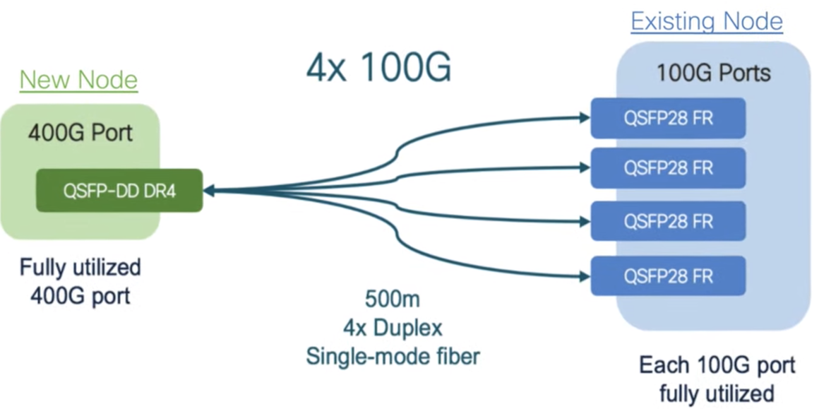
It offers 24 ports 100G and 5 or 6 ports 400G. So it’s possible to imagine cases with 2.4Tbps to the clients in 100G and 2.4Tbps to the core in 400G. But nothing prevents from breaking some or all of the 400G ports in 4x100G, to build a 32x 100G + 4x 400G systems. It’s very flexible.
A couple of examples among many other possibilities:


Keep in mind some basic concept here: you can not break a 400G interfaces and expect to connect it to existing 100G SR4, LR4 or CWDM4. The 100G port facing the breakout cable must be “1-lambda” optics like DR/FR.
The NCS57B1 internal architecture imposes two simple rules to respect when configuring ports:
- QSFP28 and QSFP+ breakout ports can only be configured on the top row and it disables the facing N+1 port
- you can not mix 4x25 break and QSFP+ (40G or 4x10G) in the same Quad.
Let’s review these two rules in details:
breakout cables in top row
This first rule only applies to the 100G ports on the left part, not the 400G capable ports on the right.
Only the ports with an even number, located on the top row, can be configured as 4x10G or 4x25G breakout.

The configuration is different than the one available on other platforms under “controller …”, it’s now done under “hw-module port-range”:
RP/0/RP0/CPU0:NCS5500(config)#hw-module port-range 6 7 ?
  instance  card instance of MPA's
  location  fully qualified location specification
RP/0/RP0/CPU0:NCS5500(config)#hw-module port-range 6 7 instance 0 location 0/RP0/CPU0 mode ?
  WORD  port mode 40-100, 400, 2x100, 4x10, 4x25, 4x10-4x25, 1x100, 2x100-PAM4, 3x100, 4x100
RP/0/RP0/CPU0:NCS5500(config)#hw-module port-range 6 7 instance 0 location 0/RP0/CPU0 mode 4x10
So the configuration is effective for two subsequent ports, in the example above it’s 6 and 7. That means, the configuration of the port of the top row will automatically disable the port on the bottom (or N+1).
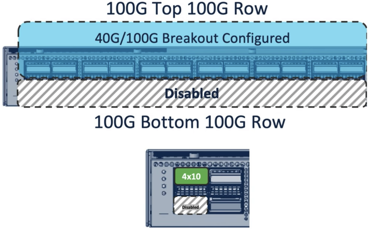
In the example below, we configured the ports 16-17 in 4x10G breakout.
RP/0/RP0/CPU0:ios#show contr npu voq-usage int all inst all loc 0/RP0/CPU0

-------------------------------------------------------------------
Node ID: 0/RP0/CPU0
Intf         Intf     NPU NPU  PP   Sys   VOQ   Flow   VOQ    Port
name         handle    #  core Port Port  base  base   port   speed
             (hex)                                     type
----------------------------------------------------------------------
Hu0/0/0/0    3c000048   0   0    9     9   1024   6160 local   100G
Hu0/0/0/1    3c000058   0   0   11    11   1104   6256 local   100G
Hu0/0/0/2    3c000068   0   0   13    13   1112   6272 local   100G
Hu0/0/0/3    3c000078   0   0   15    15   1120   6288 local   100G
Hu0/0/0/4    3c000088   0   0   17    17   1128   6304 local   100G
Hu0/0/0/5    3c000098   0   0   19    19   1136   6320 local   100G
Hu0/0/0/6    3c0000a8   0   0   21    21   1144   6336 local   100G
Hu0/0/0/7    3c0000b8   0   0   23    23   1152   6352 local   100G
Fo0/0/0/8    3c0000c8   0   0   25    25   1184   6416 local    40G
Hu0/0/0/9    3c0000d8   0   0   27    27   1160   6368 local   100G
Fo0/0/0/10   3c0000e8   0   0   29    29   1192   6432 local    40G
Fo0/0/0/11   3c0000f8   0   0   31    31   1200   6448 local    40G
Hu0/0/0/12   3c000108   0   0   33    33   1168   6384 local   100G
Hu0/0/0/13   3c000118   0   0   35    35   1176   6400 local   100G
Hu0/0/0/14   3c000128   0   0   37    37   1096   6240 local   100G
Hu0/0/0/15   3c000138   0   0   39    39   1088   6224 local   100G
Hu0/0/0/18   3c000168   0   0   45    45   1072   6192 local   100G
Hu0/0/0/19   3c000178   0   0   47    47   1064   6176 local   100G
FH0/0/0/28   3c000188   0   1   49    49   1224   6224 local   400G
FH0/0/0/27   3c0001c8   0   1   57    57   1248   6272 local   400G
FH0/0/0/26   3c000208   0   1   65    65   1240   6256 local   400G
Hu0/0/0/25   3c000248   0   1   73    73   1032   6144 local   100G
FH0/0/0/24   3c000288   0   1   81    81   1232   6240 local   400G
Hu0/0/0/20   3c0002c8   0   1   89    89   1056   6192 local   100G
Hu0/0/0/21   3c0002d8   0   1   91    91   1048   6176 local   100G
Hu0/0/0/22   3c0002e8   0   1   93    93   1040   6160 local   100G
Fo0/0/0/23   3c0002f8   0   1   95    95   1216   6208 local    40G
Te0/0/0/16/0 3c002148   0   0   41    41   1208   6464 local    10G
Te0/0/0/16/1 3c002150   0   0   42    42   1256   6480 local    10G
Te0/0/0/16/2 3c002158   0   0   43    43   1264   6496 local    10G
Te0/0/0/16/3 3c002160   0   0   44    44   1080   6208 local    10G
You notice we have now 5-tuple 0/0/0/16/x for these interfaces, proof it’s broken out in 4.
Also we see that port 17 disappeared of the inventory.
Again, these rules don’t apply to the 400G ports on the right, all of them can be configured in break-out mode.
Mixing 25G breakout and QSFP+
The second rule is technically more complex but can be summarized with the following abstraction:
“Each block of four ports (QUAD: 0-3, 4-7, 8-11, 12-15, 16-19 and 20-23) can not accept a mix of 4x25G and QSFP+ port, whether they are used in 40G or 4x10G”. All other options are supported, as long as they also follow the first rule described earlier.

A couple of not-supported use-cases.
Example 1:

Here, we start with QSPF+ 40G in port 0, then we insert a QSFP28 100G in port2.
No problem, it works.
Then we try to configure the 100G in breakout mode, 4x25G. The system refuses to commit the configuration: we can’t get QSFP+ and 4x25G in the same quad.
Example 2:

We have a QSFP+ 40G in port 0 and we configured 0-1 in 4x10G breakout mode, so port 1 is disabled.
We insert a QSFP28 100G in port2.
No problem, this configuration is supported.
Then we try to configure the 100G in breakout mode, 4x25G. The system refuses to commit the configuration for the same reason: we can’t get QSFP+ and 4x25G in the same quad.
Example 3:

We start with QSFP28 100G in ports 0 and 2.
We configure ports 0-1 in breakout mode, port 1 is disabled and now we have 4x25G in port 0.
Now we insert a QSFP+ in port 3 and the port doesn’t go up: we can’t get QSFP+ and 4x25G in the same quad.
MACsec support
Starting IOS-XR 7.6.1, MACsec is supported on NCS-57B1-5DSE-SYS and NCS-57B1-6D24-SYS. All ports are connected to PHY supporting the feature. It will be supported on 100G ports, 400G ports and also breakout ports.

MACsec configurations on NCS500/5700
Other things to know?
- We will support 10G via QSFP to SFP Adaptor (QSA). Not supported in 7.3.1, in the roadmap.
- 1G will not be supported
Conclusion
This new router is the first Jericho2-based platform in fixed form factor. It offers a very high 100G and 400G port density in a very small size (1RU).
In a future article, we will demonstrate the routing scale and prefix programming speed in J2.
Leave a Comment