
Introduction to NCS55xx and NCS5xx LPTS
Introduction
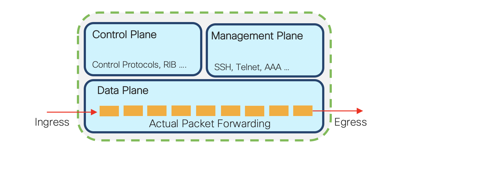
In our previous tech-notes, we focussed on exploring the data-plane security capabilities of NCS5xx and NCS55xx. In this tech-note, we will discuss the NCS55xx and NCS5xx capabilities around control plane protection. In today’s networks, control plane security is as important as data plane security. Customers need to focus on protecting the business critical control and management planes from malicious attacks and also misconfiguration events which may overwhelm the processor and bring down the router resulting in an unfortunate event. The Cisco IOS devices have the concept of control plane policing. And in IOS-XR devices, we use a very comprehensive and powerful feature called Local Packet Transport Services. (Reference).
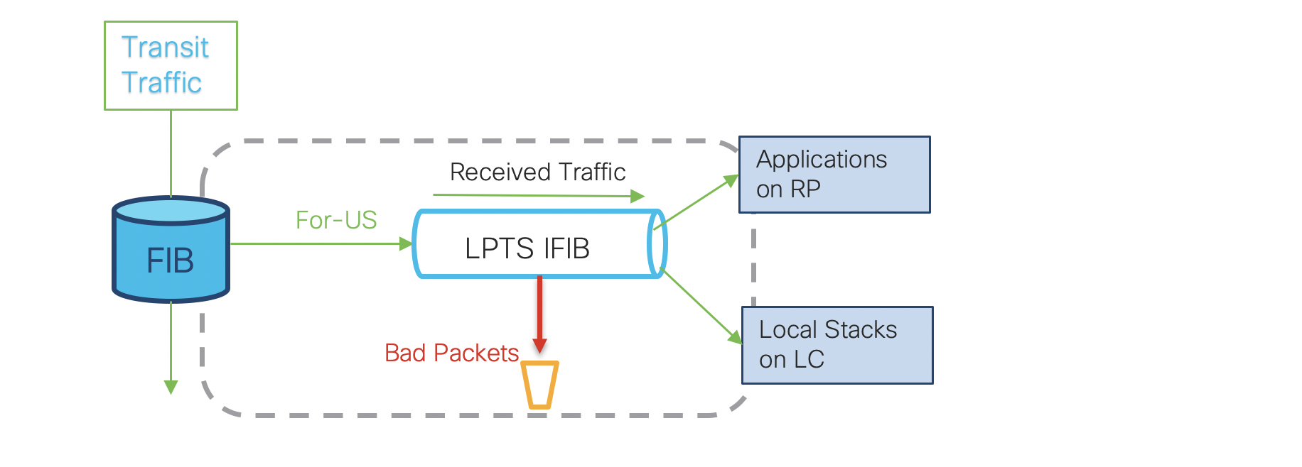
In IOS-XR LPTS, as part of “for-us” packet delivery process, the rate at which packets are delivered are selectively monitored to avoid overwhelming the CPU. LPTS filters and polices the packets based on the defined flow-type rate in hardware before punting it to the software. Punt is a popular terminology used for sending packets to the control-plane for processing. It deals with packets that require special handling or can not be switched by CEF (Cisco Express Forwarding). For more details please Visit. The LPTS takes the control plane protection (CoPP) concept to a new level by automatically applying rate limiting to all packets that must be handled by any CPU on the device. The use case of this is we achieve automated control to network health without relying on network operators, as it becomes difficult to configure these functions manually in large-scale networks.
Glossary
Before moving further, lets define the terminologies which we will be referring multiple times in the document.
| Terms | Description |
|---|---|
| CoPP | Control Plane Protection (More Details) |
| “For-us” packets | Control/management plane packets destined to or to be processed by a node/element in IOS-XR system |
| Flow | A binding between a tuple (such as protocol, local address, local port, remote address, remote port) and an element |
| FIB | Forwarding Information Base – A Table which is used to determine where a packet is to be forwarded. |
| iFIB | Internal Forwarding Information Base – A Table that is used to determine where a “for-us” packet needs to be sent inside IOS-XR running system when pIFIB look up fails |
| LPTS | Local Packet Transport Services |
| Netio | An IOS-XR process which performs packet forwarding in software, equivalent of “process switching” |
| pIFIB or pre-FIB | Compact version of IFIB. A filtered version of pIFIB, HW pIFIB is loaded into LC HW TCAM |
| Tuple | is an ordered list of integer |
| SDR | Secure Domain Router. It provide a means of partitioning a router into multiple, independent routers. (More Details) |
| SPP | Software Path Process. Its a multiplexer/demultiplexer component NPU and clients on LC/RP CPU |
| SPiO | Streamlined Packet IO is for processing L2 control packets |
LPTS Overview
LPTS is an integral component of IOS-XR systems which provides firewall and policing functionality. LPTS maintains per interface complete table in netio chain in Line card CPU, making sure that packets are delivered to their intended destinations. IOS XR software classifies all ‘For Us’ control packets into 97 different flows. Each flow has it own hardware policer to restrict the punt traffic rate for the flow type. In traditional IOS-XR platforms (CRS/ASR9k) LPTS had different regions which consumed 16k entries each. But we do not have the same luxury in NCS55xx and NCS5xx due to limited TCAM resources. We need to use these resources very wisely to accomodate several features and functionalities. Therefore to minimize the usage of resources, the LPTS platform dependent (PD) layer programs only the protocol default entries in the hardware. It punts the control packets to Line card CPU Netio for full lpts lookup in LPTS Decap node. We will see this in details in later sections. The Network Input/Output (NetIO) process is responsible for forwarding packets in software. (For deeper understanding of process switching and slow path please refer).
LPTS also plays a vital role in support of NSR (Non Stop Routing) enabled control plane. LPTS will make use of the fabric infrastructure for “for-us” control packets to both Active and Standby RP for NSR enabled processes. LPTS also installs dynamic flow entries for certain protocol packets on-demand. An example would be, for ICMP echo request sent out from the local router to peer router. LPTS will create flow entry in Pre-IFIB so that ICMP echo reply received from the peer router will be matched against it.
Note: LPTS is applicable only for control and management plane traffic entering into the router and destined to the local router. Packets originated by the router and transit traffic are not processed by LPTS.
Main Components of LPTS
The three component which LPTS needs to accomplish its task are:
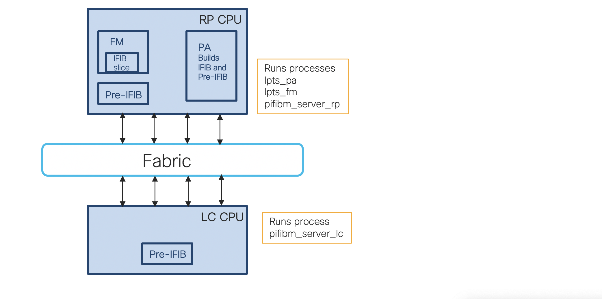
- Port Arbitrator Process
- Aggregates bindings into flows
- Generates IFIB and Pre-IFIB
- Allocates Flow Group IDs
- Does not touch packets
- Flow Manager Process
- Copies IFIB slice updates from the Port Arbitrator to netio
- Does not touch packets
- Acts as a Sub-Server to the Port Arbitrator
- Pre-IFIB Manager Process
- Copies Pre-IFIB updates from the Port Arbitrator to netio
- Filters and translates Pre-IFIB updates into TCAM updates
- Does not touch packets
LPTS in Pipeline Architecture
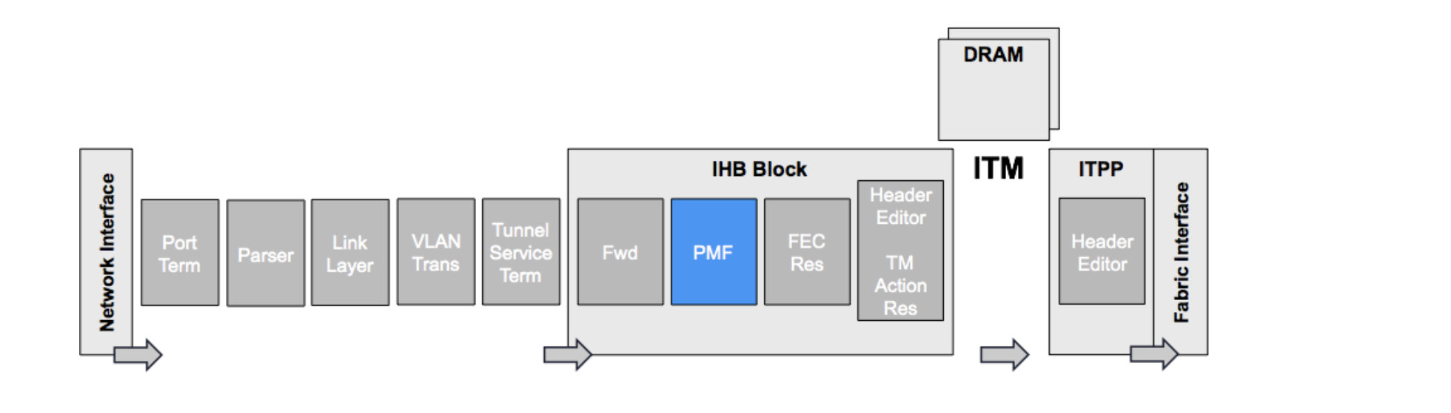
The Programmable Mapping and Filtering (PMF) engine block in IRPP forwarding asic is the most programmable block in the TCAM. It contains all the information of previous blocks like incoming PP port, packet type, forwarding lookup results. It also classifies packets based on predefined protocol fields all the way from Layer 2 to Layer 7. Based on these classifications, various actions can be applied to the packet. LPTS uses the PMF architecture to classify the packet and other pre-processing attributes to apply action (punt CPU, stats and police).
NPU and Line Card CPU in action
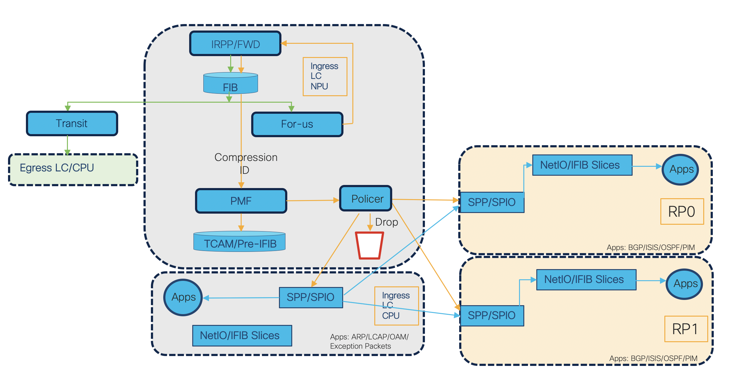
- 1) A frame is received on the ingress interface of NCS55xx or NCS5xx. On receiving the packet necessary layer 1 and 2 checks are performed and layer 3 information is extracted from the packet and passes it to the forwarding ASIC.
- 2) Packet enters the ingress pipeline and traps are generated based on forwarding lookup.
- 3) The L3 forwarding engine does a Forwarding Information Base (FIB) lookup and determines whether the packet is a locally destined “for_us” packet. This is the first pass. The two traps generated are RxTrapReceive (for L3 packets) and RxTrapUserDefine_RECEIVE_L2 (for L2 packets).
- 4) By looking at the traps, the packets are recycled to ingress pipeline by skipping the egress pipeline lookups. The lookup key can contain various values such as: source IP, destination IP, source L4 port, destination L4 port, interface, vrf and compression id.
- 5) This TCAM lookup happens in PMF. The “for-us” control packets are then punted by encapsulating in the NPU header. In NPU, the “for-us” control packets undergo hardware TCAM lookup which will hit one of the protocol default TCAM entries. NPU header contains the control information such as – ingress port, destination node, trap code, trap qualifier, listener_tag, flow type, stats pointer etc.
- 6) LPTS entries are installed as 4 main groups i.e. IPv4, IPv6, CLNS and L2. In first pass the traps are different for L2 and L3 because the lookup tables are different which are generating the traps. After such classification, packets go into Software Path Process (SPP), that selects whether to send to L2/SPIO or NetIO process. The packets are received by SPP in IOS-XR by opening a raw socket to listen over the punt interface. SPP is a component that classifies packets in punt path to identify its client. Moreover, SPP does the parsing of npu header to extract the control information filled by NPU. However, it retains the npu header. Based on this parsing results it decides the client. (In our case NetIO or L2/SPIO). In case, there is no proper decision, the packet is forwarded to NetIO as a default client.
- 7) NetIO handles L3 Protocol Packets like ICMP, OSPF, BGP etc. Based on lookup result, the control packets will get policed and punted to LC CPU.
- 8) In case of errors, the packets are also punted for diagnostics (even if npu decides it to drop) or for some action (to generate ICMP error) via traps from first pass itself and policed.
- 9) When the “For Us” packets are received by the LPTS decap node in NetIO, LPTS does iFIB lookup and find the packet associated protocol client and deliver the packet to the protocol stack. Most of the times this lookup is skipped and that provides the performance as use the work done in NPU to be avoided in CPU.
- 10) The Streamlined Packet IO - SPIO is used by L2 processes CFM,STP,ARP etc. When a reaches from SPP to NetIO/SPIO, the control information is transferred. NetIO/SPIO strip off the npu header and process the actual packet.
- 11) The CPU runs the software processes that decapsulate the packet and deliver them to the correct stack.
Note: Modular systems will have 2 Route Processors (RP). For fixed platforms there will be only 1 Route Processor (RP).
Sample result of a LPTS entry
We have configured ISIS on the interface Ten0/0/0/6 and Ten0/0/0/7. Let us check the LPTS hardware entry.
RP/0/RP0/CPU0:N55-24#show isis neighbors
IS-IS 1 neighbors:
System Id      Interface        SNPA           State Holdtime Type IETF-NSF
N540-49        Te0/0/0/7        *PtoP*         Up    28       L2   Capable
N540-49        Te0/0/0/6        *PtoP*         Up    26       L2   Capable
RP/0/RP0/CPU0:N55-24#show lpts pifib hardware entry location 0/0/CPU0 | beg TenGigE0/0/0/6
Interface         : TenGigE0/0/0/6
Is Fragment       : 0
Domain            : 0-default
Listener Tag      : IPv4_STACK
Flow Type         : PIM-mcast-known
DestNode          : Deliver RP0
Dest Type         : Dlvr
Punt Queue Prio   : MEDIUM
Hardware NPU Data
-------
NPU               : 0
TCAM entry        : 209
Policer_id        : 0x7d78
Stats_id          : 0x800001fd
Stats_hdl         : 0x8ed4ef10
Compression_id    : 0x1
Accepted/Dropped  : 0/0
---------------------------------------------------
As we discussed in the previous sections the hardware lookup results contains various fields like Interface, DestNode, Listener Tag, Flow-type and the hardware NPU data. Similarly we can get the output of default flow types as well. Policing is offloaded to NPU before packets hits the CPU to provide control plane security. Each flow policer has default static policer rate value. Each flow policer value can be configured from 0 (to drop all packet matching classification criteria) to max of 50K PPS as compared to 100k in ASR9k. Similar to ASR9k platform, the LPTS policers work on a per NPU basis. For example, if the LPTS police value is set to 1000pps for a flow, it means that every NPU on the LC can punt with 1000pps to the CPU for that flow.
LPTS takes effect on all applications that receive packets from outside the router. LPTS functions without any need for customer configuration. However, the policer values can be customized if required. As we saw the ISIS known default police value is 2100.
RP/0/RP0/CPU0:N55-24#show lpts pifib hardware police location 0/0/CPU0 | in PIM-mcast-known
PIM-mcast-known        32120   Static  2100      2078      0         0-default
We can configure it to a new value and see that it is taking affect. So now if the control packets goes beyond 1000 pps the packets will be policed.
RP/0/RP0/CPU0:N55-24(config)#lpts pifib hardware police flow Pim multicast known rate 1000
RP/0/RP0/CPU0:N55-24#show lpts pifib hardware police location 0/0/CPU0 | in PIM-mcast-known
PIM-mcast-known        32120   Global  1000      1000      0         0-default
Note: You should be very careful while changing this default values. The generic best practice for LPTS is to use the default configurations and not change anything.
LPTS can use the following tuples to identify a packet:
| Tuples |
|---|
| VRF |
| L3-protocol |
| L4-protocol |
| Interface |
| Source Address |
| Source Port |
| Destination Address |
| Destination Port |
Supported Flow Types in Hardware LPTS as per IOS-XR 7.2.1
The below command displays pre-Internal Forwarding Information Base (pIFIB) information for the designated node. It shows all the Flow Types supported and their default policer values.
RP/0/RP0/CPU0:N55-24#show lpts pifib hardware police location all
Handling Exception Packets
Sometimes routers need to manage unexpected packets that are not meant as “for-us” packets and software intervention is required to handle them. Therefore they need to be sent to the CPU. These packets are also known as exception packets (TTL expired, invalid headers, adjacency not available etc). For example, if a destination address is not present in the FIB and results in a miss, then an ICMP unreachable packet needs to be generated and sent back to the source system of the packet. Thus, it needs to be processed by RP CPU. Another example may be Glean Adjacency. If a L2 MAC address for a destination ip address or next hop is not present in the FIB, the packet gets sent to the LC CPU to trigger ARP request destined to the host or next-hop. These type of scenarios are handled by hardware traps. Traps are specific predefined rules in NPU. All hardware traps are statically programmed with predefined policer rates per NPU. LPTS on the other hand is dynamic and entries are created as per configurations. Whereas traps get defined in the router during the bootup itself. Same as LPTS punt policers, these trap policers can be configured with policer rate values from 0 pps (for complete drop) till predefined max limit per trap. As mentioned above, we need to take care while changing the default values as that will impact both functionality and CPU performance.
The below output shows the full list of supported traps. (Full List of RX Traps)
You can notice that for lpts flows and policer values we used the command
RP/0/RP0/CPU0:N55-24#show lpts pifib hardware police location all
We check the hardware entries in the pIFIB. As mentioned above traps being rules in npu we need to check the npu stats for all the traps. Below command shows all the supoprted traps.
RP/0/RP0/CPU0:N55-24#show controllers npu stats traps-all instance all location 0/0/CPU0
How to check the default policer value of individual traps
RP/0/RP0/CPU0:N55-24#show controllers npu stats traps-all instance all location 0/0/CPU0 | in Ttl
RxTrapIpv4Ttl0                                0    108  0x6c        32010   0                    0  RxTrapIpv4Ttl1                                0    112  0x70        32010   0                    0 RxTrapMplsTtl0                                0    141  0x8d        32014   0                    0  RxTrapMplsTtl1                                0    142  0x8e        32014   0                    0
RP/0/RP0/CPU0:N55-24#attach location 0/0/CPU0
Tue Oct  6 16:04:19.751 UTC
Last login: Tue Oct  6 15:56:35 2020 from 172.0.16.1
export PS1='#'
[xr-vm_node0_0_CPU0:~]$export PS1='#'
#dpa_show puntpolicer | grep -e Def -e 32010
                  Def CIR Rate  Conf CIR Rate  CIR Burst         ID
 10 -  0:            100              0        100      32010
From the above output we can see the trap policer default value is 100 pps.
Configuring new policer rate
RP/0/RP0/CPU0:N55-24#show running-config lpts
Tue Oct  6 16:05:05.994 UTC
lpts punt police location 0/0/CPU0
 exception ipv4 ttl-error rate 200
RP/0/RP0/CPU0:N55-24#attach location 0/0/CPU0
Tue Oct  6 16:05:21.713 UTC
Last login: Tue Oct  6 16:04:19 2020 from 172.0.16.1
export PS1='#'
[xr-vm_node0_0_CPU0:~]$export PS1='#'
#
#dpa_show puntpolicer | grep -e Def -e 32010
                      Def CIR Rate  Conf CIR Rate  CIR Burst         ID
 10 -  0:            100            200        100      32010
From the above output we can see that new policer value has been programmed in the hardware. Similarly we can change the default trap policer values of exception and protocol packets.
Dynamic LPTS Flow Type
In limited hardware resource platforms like NCS55xx and NCS5xx, we cannot support all LPTS flows in the TCAM hardware where resources are shared across multiple features. Therefore there is a need to provide configurable option for customers to decide what flow types they need to program in the hardware and maximum lpts entry per flow type. This can help in saving a lot of hardware resources. Customers can dynamically turn on/off a particular flowtype and max entry for the type using the CLI to decide the LPTS entries to be programmed in the hardware. This feature is supported from IOS-XR 6.2.x onwards.
Feature Support
- All the mandatory entries will be programmed in TCAM irrespective of configurations.
- If we do not configure the new CLI, the pifib process will have the default behavior as earlier without any flow limitation or maximum size set.
- For unsupported flow types we will get errors in the platform.
- Flowtype maximum values learned from the configuration will take precedence to the default list.
- Un-configured flows will be set to default static values set by platform.
- Non-Mandatory entries can also be configured using the same CLI.
- The configuration has local scope - meaning we can set different flows and maximum flows per Line Card.
- Maximum hardware entries across all lpts flows is 8k.
- Let us verify the same with below output
RP/0/RP0/CPU0:N55-24#show lpts pifib dynamic-flows statistics location 0/0/CPU0
 Dynamic-flows Statistics:
 -------------------------
 (C - Configurable, T - TRUE, F - FALSE, * - Configured)
 Def_Max  - Default Max Limit
 Conf_Max - Configured Max Limit
 HWCnt    - Hardware Entries Count
 ActLimit - Actual Max Limit
 SWCnt    - Software Entries Count
 P, (+)   - Pending Software Entries
   FLOW-TYPE           C  Def_Max Conf_Max     HWCnt/ActLimit      SWCnt P
 -------------------- -- ------- --------   -------/--------    ------- -
 Fragment             T        4       --         2/4                 2
 OSPF-mc-known        T      600       --         6/600               6
 OSPF-mc-default      T        8       --         4/8                 4
 OSPF-uc-known        T      300       --         3/300               3
 OSPF-uc-default      T        4       --         2/4                 2
 ISIS-known           T      300       --         4/300               6 +
 ISIS-default         T        2       --         1/2                 1
 BGP-known            T      900       --         2/900               2
 BGP-cfg-peer         T      900       --         2/900               2
 BGP-default          T        8       --         4/8                 4
 PIM-mcast-default    T       40       --         0/40                0
 PIM-mcast-known      T      300       --        10/300              10
 PIM-ucast            T       40       --         2/40                2
 IGMP                 T     1164       --        31/1164             31
 ICMP-local           T        4       --         4/4                 4
 ICMP-control         T       10       --         5/10                5
 ICMP-default         T       18       --         9/18                9
 ICMP-app-default     T        4       --         2/4                 2
 LDP-TCP-known        T      300       --         1/300               1
 LDP-TCP-cfg-peer     T      300       --         1/300               1
 LDP-TCP-default      T       40       --         0/40                0
 LDP-UDP              T      300       --         2/300               2
 All-routers          T      300       --        10/300              10
 RSVP-default         T        4       --         1/4                 1
 RSVP-known           T      300       --         2/300               2
 SNMP                 T      300       --         0/300               0
 SSH-known            T      150       --         0/150               0
 SSH-default          T       40       --         0/40                0
 HTTP-known           T       40       --         0/40                0
 HTTP-default         T       40       --         0/40                0
 SHTTP-known          T       40       --         0/40                0
 SHTTP-default        T       40       --         0/40                0
 TELNET-known         T      150       --         0/150               0
 TELNET-default       T        4       --         1/4                 1
 UDP-known            T       40       --         0/40                0
 UDP-listen           T       40       --         2/40                2
 UDP-default          T        4       --         2/4                 2
 TCP-known            T       40       --         0/40                0
 TCP-listen           T       40       --         0/40                0
 TCP-default          T        4       --         2/4                 2
 Raw-default          T        4       --         2/4                 2
 ip-sla               T       50       --         0/50                0
 EIGRP                T       40       --         0/40                0
 PCEP                 T       20       --         0/20                0
 GRE                  T        4       --         2/4                 2
 VRRP                 T      150       --         0/150               0
 HSRP                 T       40       --         0/40                0
 MPLS-oam             T       40       --         2/40                2
 DNS                  T       40       --         0/40                0
 RADIUS               T       40       --         0/40                0
 TACACS               T       40       --         0/40                0
 NTP-default          T        4       --         0/4                 0
 NTP-known            T      150       --         0/150               0
 DHCPv4               T       40       --         0/40                0
 DHCPv6               T       40       --         0/40                0
 TPA                  T      100       --         0/100               0
 PM-TWAMP             T       36       --         0/36                0
---------------------------------------------------
 Active TCAM Usage : 7960/8000 [Platform MAX: 8000]
 HWCnt/SWCnt       : 123/130
---------------------------------------------------
From the above output we can see the maximum entries supported in the hardware is 8000. Let us take example of our ISIS configuration. From the output we can see 300 entries alllocated for ISIS- PIM-mcast-known. That means for 300 sessions we will have the hardware programming or entries and we will be able to track that via LPTS and subjected to the properties of hardware LPTS (police/stats etc). The entries above 300 will be programmed in sofware. This can be seen via the column SWCnt. All the entries which are not having entries in hardware will be kept under a common pool in sofware and will be subjected to the properties different than hardware LPTS. Let us take an example of expanding the max entries from 300 to 400.
Note: It is recommended to use HW flows and have no software flow.
RP/0/RP0/CPU0:N55-24(config)#lpts pifib hardware dynamic-flows location 0/0/CPU0
RP/0/RP0/CPU0:N55-24(config-pifib-flows-per-node)#flow isis known max 400
RP/0/RP0/CPU0:N55-24(config-pifib-flows-per-node)#commit
% Failed to commit one or more configuration items during a pseudo-atomic operation. All changes made have been reverted. Please issue 'show configuration failed [inheritance]' from this session to view the errors
RP/0/RP0/CPU0:N55-24(config-pifib-flows-per-node)#show configuration failed
Wed Oct  7 08:42:42.338 UTC
!! SEMANTIC ERRORS: This configuration was rejected by
!! the system due to semantic errors. The individual
!! errors with each failed configuration command can be
!! found below.
lpts pifib hardware dynamic-flows location 0/0/CPU0
 flow isis known max 400
!!% invalid max_limit value input: Platform MAX limit is 8000. But the configured flow max value is 8060. Please decrement config total by 60 OR increase Platform MAX.
!
end
```
We can see that we are crossing the max limit due to which our configuration is getting rejected. How to overcome this ? To overcome this limitation we need to compromise on reducing max entries for other flow type. This will be different for every customers. Say for example customer decides reduce the IGMP to accomodate the extra ISIS entries.
RP/0/RP0/CPU0:N55-24#show running-config lpts
Wed Oct  7 08:49:44.605 UTC
lpts pifib hardware dynamic-flows location 0/0/CPU0
 flow pim multicast known max 400
 flow igmp max 500
RP/0/RP0/CPU0:N55-24#show lpts pifib dynamic-flows statistics location 0/0/CPU$
 Dynamic-flows Statistics:
 -------------------------
 (C - Configurable, T - TRUE, F - FALSE, * - Configured)
 Def_Max  - Default Max Limit
 Conf_Max - Configured Max Limit
 HWCnt    - Hardware Entries Count
 ActLimit - Actual Max Limit
 SWCnt    - Software Entries Count
 P, (+)   - Pending Software Entries
  FLOW-TYPE           C  Def_Max Conf_Max     HWCnt/ActLimit      SWCnt P
 -------------------- -- ------- --------   -------/--------    ------- -
 Fragment             T        4       --         2/4                 2
 OSPF-mc-known        T      600       --         6/600               6
 OSPF-mc-default      T        8       --         4/8                 4
 OSPF-uc-known        T      300       --         3/300               3
 OSPF-uc-default      T        4       --         2/4                 2
 ISIS-known           T      300       --         4/300               6 +
 ISIS-default         T        2       --         1/2                 1
 BGP-known            T      900       --         2/900               2
 BGP-cfg-peer         T      900       --         2/900               2
 BGP-default          T        8       --         4/8                 4
 PIM-mcast-default    T       40       --         0/40                0
 PIM-mcast-known      T*     300      400        10/400              10
 PIM-ucast            T       40       --         2/40                2
 IGMP                 T*    1164      500        31/500              31
Different Flow Type Categories
| Flow Type | Details |
|---|---|
| Not supported | Flow types not supported by platform. All LPTS PI cli configuration will return error for unsupported flow types. |
| Supported, Default and Mandatory | Flow types Supported by platform and not configurable. Fragment Raw-Default OSPF Unicast default OSPF Multicast default - 224.0.0.5, 224.0.0.6, ff02::5 and ff02::6 BGP default - two entry with src and dest port as 179 ICMP-local ICMP-control ICMP-default ICMP-app-default All-routers SSH-default GRE SNMP PIM-mcast-default VRRP PIM-ucast IGMP UDP default TCP default ISIS default RSVP default Telnet default DNS NTP default LDP-UDP |
| Supported, Default and non-mandatory | Default flow types which will be programmed in the hardware at process boot. These flows are also configurable via cli. |
| Configurable | Flows that are configurable via cli (non-default). Download to hardware based on cli config or profile. BGP-known BGP-cfg-peer LDP-TCP-known LDP-TCP-cfg-peer SSH-known Telnet Known NTP known LDP-UDP OSPF-uc-known OSPF-mc-known RSVP known ISIS known TPA |
LPTS Best Practices
- Cisco Control Plane Best Practices guide can be used as a best pratice. We will have a separate document dedicated for LPTS best pratices for NCS5500 and NCS500 portfolio as per use cases.
Reference
Thanks
A very big thanks to Balamurugan Subramanian (balasubr), Dipesh Raghuvanshi (diraghuv), Prafull Soni (sprafull) for their critical inputs during the collateral.
Summary
Hope this content was useful and you understood the importance of LPTS and its implementation on the platform. To summarize LPTS consists of three main functions: Filtering of what can be punted and categorised as a flow. Decides where the flow needs to go to. Policing of the flows per NPU. The key message is, LPTS functions without the need for any explicit configuration and is always ON feature on all routing platforms that run IOS-XR. Important thing to remember, LPTS is applicable for control plane traffic (“for-us” only traffic) entering into the router and destined to the local router. Packets originated by the router and transit traffic are not processed by LPTS. Besides performing forwarding of “for-us” packets to the right destination, it also polices the incoming “for-us” packets in the LC hardware. Whatever we saw in this document is at the global level. This takes effect on the entire router. In the next tech note we will cover how we can fine tune the hardware policing specific to domains. Stay tuned till then !!!
Leave a Comment