
NCS1002 Configuration Automation Overview
This tutorial will be the first in a series of posts related to the automation of configuration for Cisco Optical products. In this tutorial, I will explain how to use OpenConfig models to configure an optical device. Cisco Optical products include NCS1002 (terminal device) and NCS1001 (line amplifier). NCS1002 and NCS1001 are complementary to each other and essential elements of Cisco highly scaled and reliable multi-terabit DCI solution. NCS1002 configuration automation will be covered first, following with details for NCS1001 in later posts.
There are several ways to make repetitive work easier for you:
- One way is to implement CLI automation with different scripts using programming languages like Python or Go. Going down this path will help with automation of configuration, but it results in more complex and less portable automation code.
- Another way is to automate configuration using data models. Data models provide a clear representation of the capabilities of a networking device with a definition that is structured, well defined and computer friendly. Usually, data models come in two forms: native or open.
- Native data models are defined by a vendor for its products and cover the widest range of possible configurations.
- Open data models are usually defined by a group of companies and/or standards bodies (OpenConfig, IETF, etc). Open models cover limited range of configurations, but are vendor neutral. Support for OpenConfig models on Cisco platforms is increasing with each new XR release.
Cisco publishes supported Native and OpenConfig models for each XR release on GitHub. Models for other Cisco operating systems can be found in the parent directory.
Slice configuration overview
The NCS1002 has 4 slices and each slice has 5 client ports and 2 line (or trunk) ports. Slice configuration depends on client speed (10G/40G/100G) and line port mode (100G/200G/250G). You need to configure a slice with proper mapping between client and line ports. OpenConfig models use the same approach, but more layers of mapping are used to support universality across vendors.
Here is a high-level scheme of OpenConfig mappings:
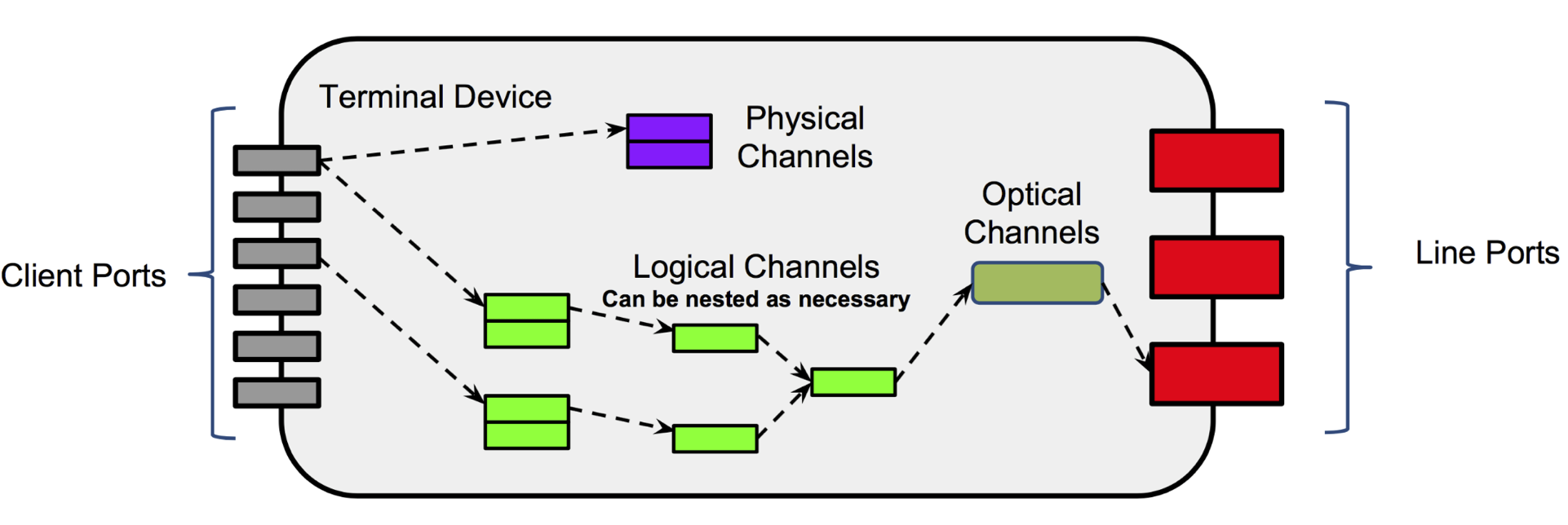
- Client port corresponds to a physical client transceiver (e.g. SFP+, QSFP, QSFP28)
- Physical channels correspond to a mapping between client ports and physical channels (e.g. 40G −> 4x10G mode will have one client port and 4 physical channels)
- Logical channels define a nested structure to ensure proper mapping between client and line (trunk) facing ports
- Optical channels correspond to a single optical carrier, wavelength and power
- Line ports represent a container for optical channels that corresponds to a physical port.
There are three OpenConfig models that are needed to configure a slice in NCS1002:
- openconfig-interfaces
- openconfig-terminal-device
- openconfig-platform
All three models are required to fully configure a slice.
Slice mappings within NCS1002
OpenConfig models give you many levels of hierarchy, but how does this apply to NCS1002? In the figures below, you can find logical representations of five slice modes implemented on NCS1002 using OpenConfig models (Slice0 is used as an example).
1.OpenConfig configuration for 2x100GE → 2x100G slice mode
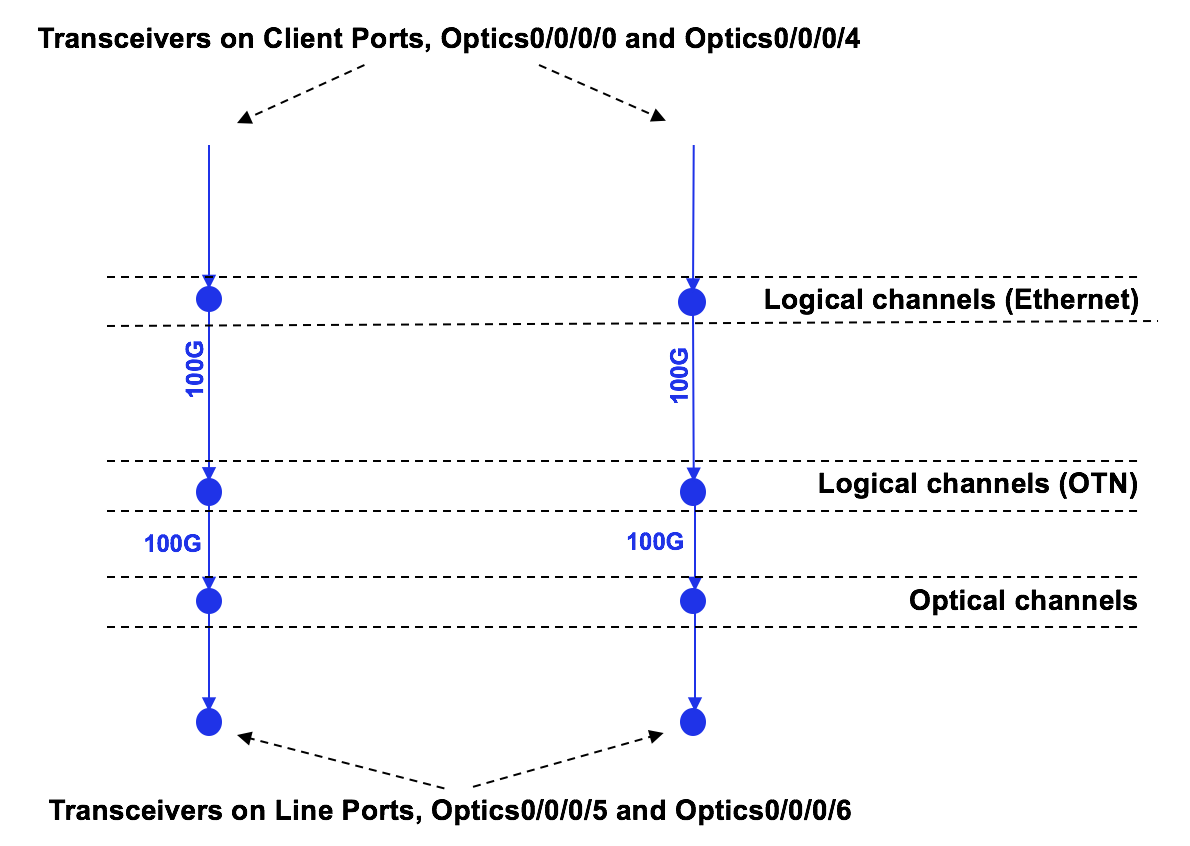
This is the simplest mode supported in NCS1002. The speed of each line port equals the speed of any client port. In this mode, you have direct 1-to-1 mappings between client ports and line (trunk) ports. Because of this, the OpenConfig configuration is very straightforward and transparent.
2.OpenConfig configuration for 4x100GE → 2x200G slice mode
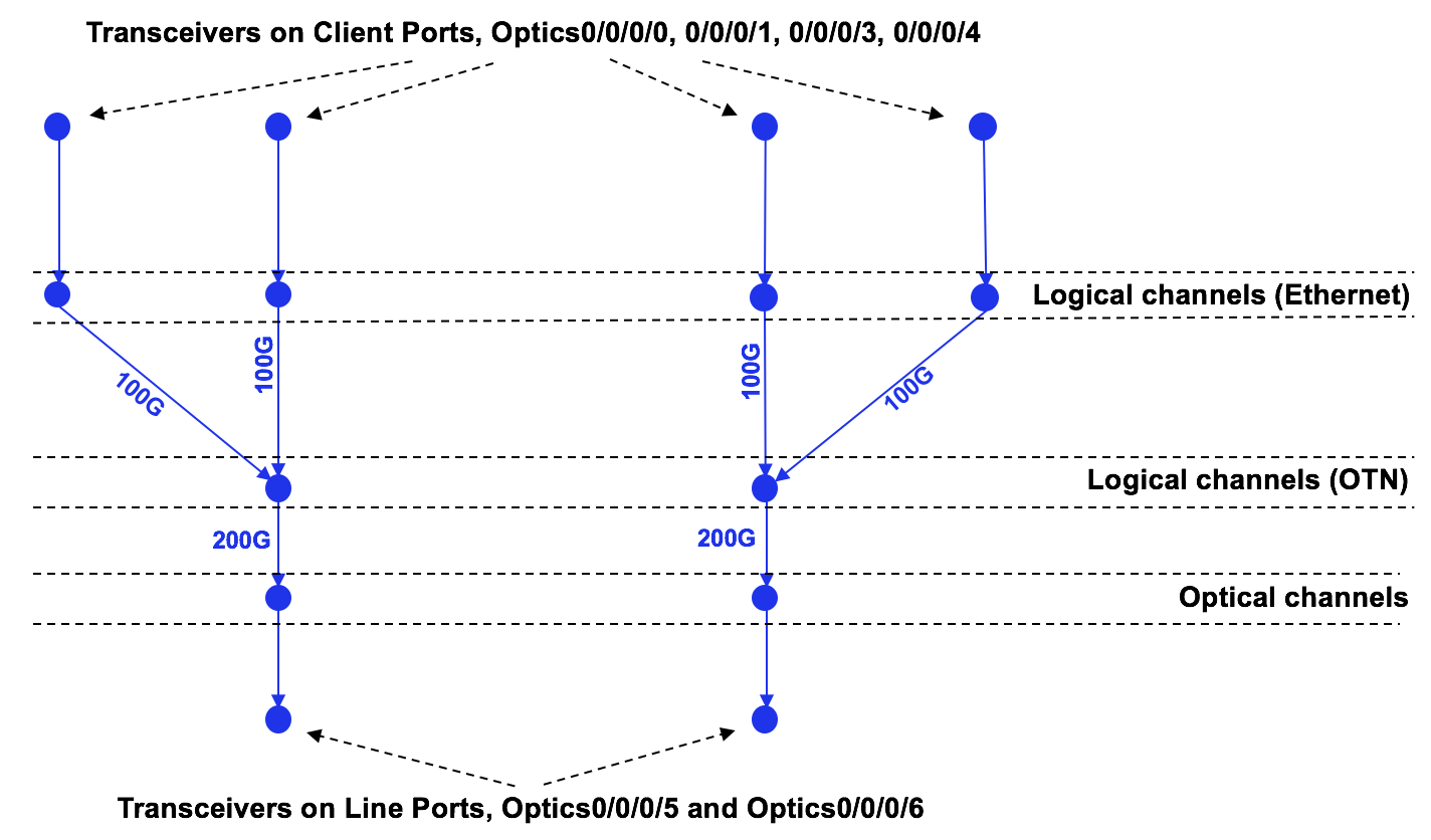
In this mode, the line port 16-QAM modulation allows you to have two client ports mapped to a single line port. In other words, 2x100GE client ports go to a single 200G line port and a slice has two groups in total. OpenConfig configuration is also simple; you just need to make sure that each pair of client ports is mapped to the same line port.
3.OpenConfig configuration for 5x100GE → 2x250G slice mode
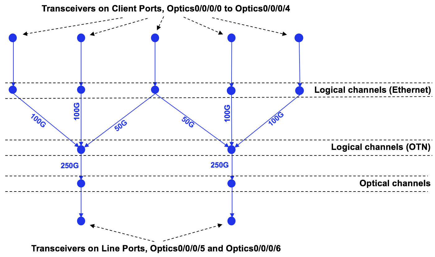
The 5x100GE → 2x250G mode gives you possibility to fill the spectrum in the densest way, as you can put all five clients into two standard-grid wavelengths. OpenConfig configuration is a bit trickier here. As in the previous mode, you need to map channels equally across both line ports. Mapping of “border” client ports (first, second, forth and fifth) is transparent. You just need to map each group into a single line port as explained in the second slide mode described above. However, the third channel needs to be mapped into both line ports in a 50/50 ratio.
4.OpenConfig configuration for 10G client ports
In addition to 100G client ports, 10G client ports are also very popular. NCS1002 supports two different modes for mapping 10G clients into line ports:
- 20x10GE → 2x100G
- 20x10GE → 1x200G
Here is a logical view of the 20x10GE → 2x100G mode:
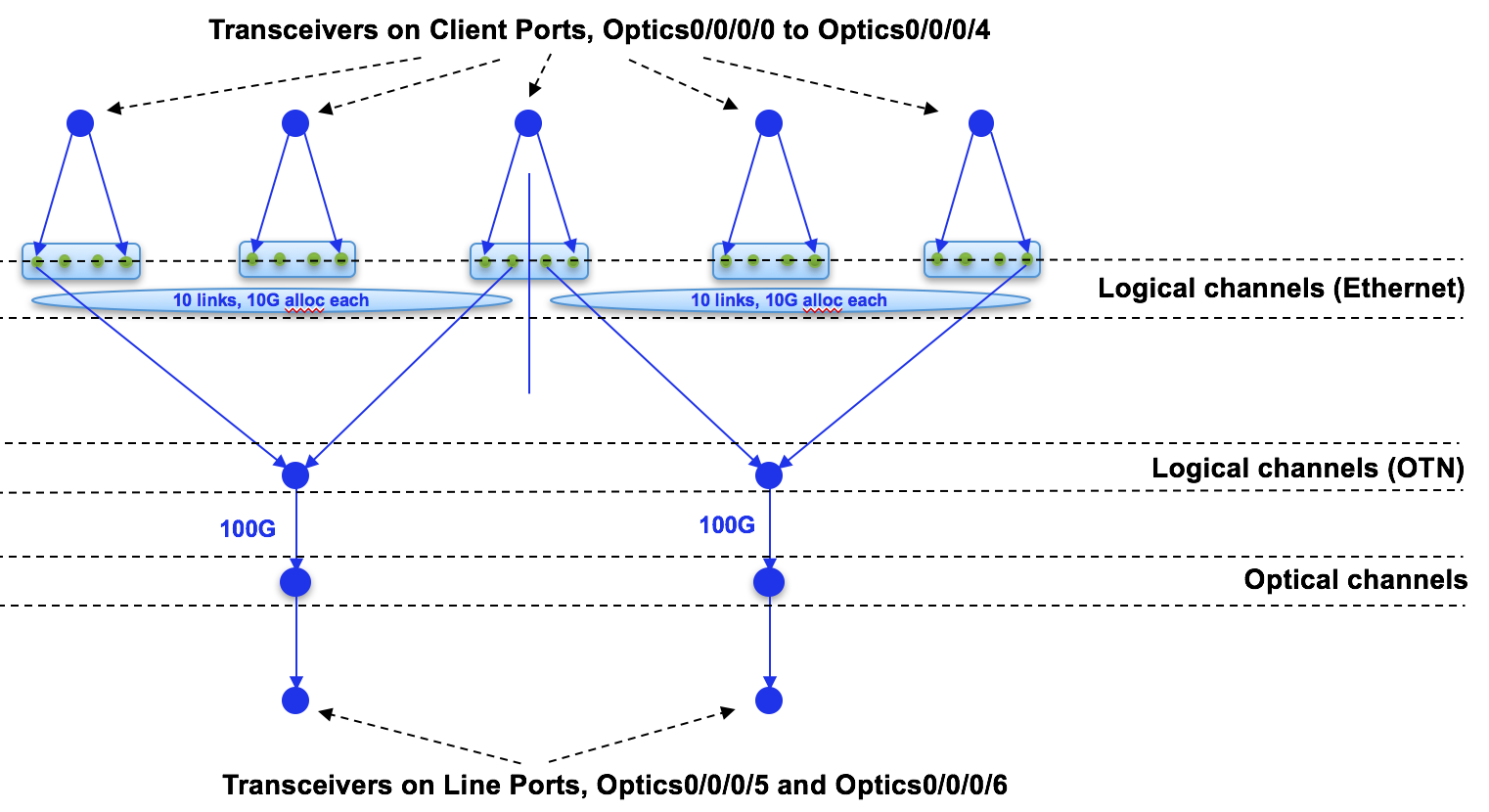
This mode is similar to the 5x100GE → 2x250G mode, as you need to map groups of client ports into line ports. The first group of ports goes into the first line port and the last group of ports goes into the second line port. As in previous example, the middle group of ports is distributed equally between both line ports.
And the final mode is 20x10GE → 1x200G:
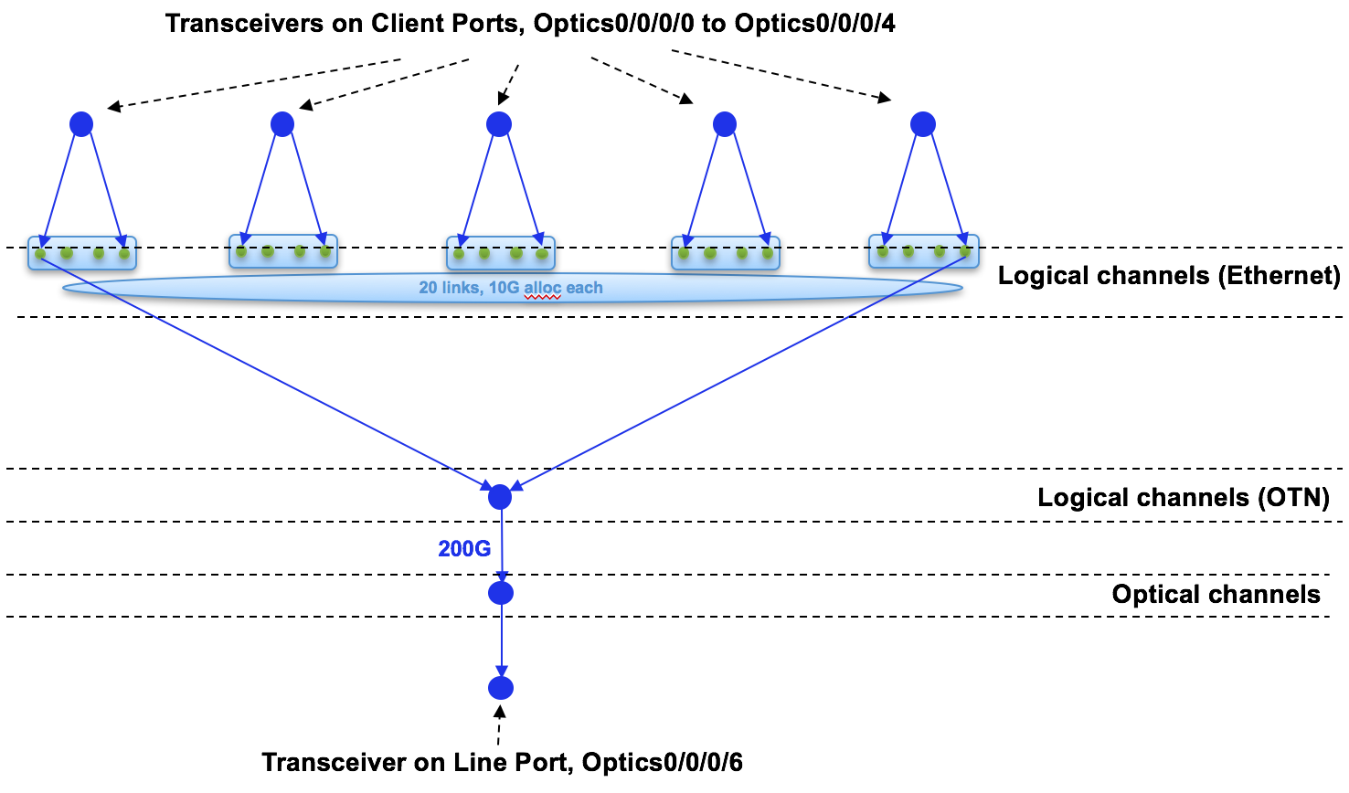
The modulation scheme allows a line port to hold all 20x10GE client ports. That’s why the entire mapping is simple; you just need to map all client ports into a single available line port.
Conclusion
NCS1002 is based on IOS XR and gives amazing capabilities for you to bring automation and programmability at full scale. These tools can dramatically save you time to bring platforms up during your installations. In our next post we will give an example of how to configure those defined mappings. Stay tuned!
Leave a Comment