Dynamic Packet Buffering
Intelligent Packet Buffering on ASR9000 4th Generation Ethernet Line cards
Document Purpose
The ASR9000 4th Generation Ethernet line cards implement intelligent packet buffering techniques to provide high performance deep buffering. In addition to enhancements to the existing static buffer management logic, the new generation of Ethernet line cards introduces dynamic buffer management.
Dynamic buffer management takes advantage of on-demand buffer allocation for efficient handling of instantaneous traffic bursts and it is optimized for high bandwidth interfaces on dense line cards. Packet buffers are designed to absorb incoming traffic temporary bursts, while guarantee for high priority traffic forwarding. For such scenarios, dynamic buffer management techniques are more efficient than static allocations, as they allow assignment of available buffers to physical interfaces on an interim basis only. They become even more relevant in the case of high-speed interfaces due to the amount of memory required to buffer traffic even for very short periods of time.
The following sections will describe these new and enhanced buffer allocation mechanisms in detail.
High Bandwidth buffering and Model Shifting
Service provider edge (PE) router plays a crucial role in the network, aggregating large quantity of traffic requiring network service handling (e.g. business L2 or L3VPN) from tens to hundreds of access devices. Therefore, the aggregation capacity of a PE router, in terms of number of access devices per port, is high. Simultaneously, each of those devices, expects to receive large volumes of downstream data from content delivery and service providers over the core network. That can often result in congestion at the PE due to bulk of traffic waiting to be delivered into the access network. There can be instantaneous traffic burst or even periods of sustained network congestions on the edge routers. As a result, the packet-buffering model must find efficient ways to carve memory during congestion in any given subset of ports, while ensuring fairness across all ports and honoring the different traffic priorities.
The dramatic increase in forwarding throughput and port densities in the recent years, coupled with the growing aggregation scale on converged network elements, has pushed the boundaries on achievable packet processing speeds and per-packet memory access performances. Integrating very large packet buffer memories with the super-high throughput network processor (NP) is prohibitive from a cost and power perspective. That is due to asymmetric technology improvements in NP throughput growth vs. commodity memory performance. As a rule of thumb, edge routers require 50ms of line-rate output queue buffers. This translates to 625 MB of high-speed packet buffering for a single 100G interface, compared to the mere 6.25 MB for 1G ports.
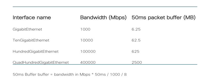
Figure 1.1 Interface Bandwidth and Buffer Space Demanding
Figure 1.1 shows how the increase in port bandwidth has directly affected the requirements for buffer space. These changes are driving more efficient and flexible packet buffer allocation models on ASR9000 4th Generation line cards.
Moreover, ASR9000 4th Generation Ethernet linecards employ a new memory technology known as High Bandwidth Memory (HBM), which provides high performance memory bandwidth at decreased power consumption. The HBM memory has multiple access channels that can be used simultaneously by different NP components, resulting in a very high memory access throughput. 
Intelligent dynamic packet buffer management
With Ethernet interface speeds transitioning from 10Gbps to 100Gbps or even 400Gbps, and denser line cards, the system demand for packet buffering has exploded to up to hundreds of GBs of high bandwidth memory. This is several orders of magnitude higher than what the current HBM technologies can provide at a reasonable cost and power consumption. The ASR9000 4th Generation Ethernet line cards are addressing this transition, by implementing a dynamic, shared packet buffer behavior.
The new approach enables the HBM to maximize burst absorption through on-demand buffer allocation, while sharing resources among all network ports that are part of the same Network Processor (NP). As an example, this enables an HBM memory that could provide 50ms of per-port buffering in a static buffer management model to buffer up to 100ms, when not all ports on the NP are congested. Moreover, the 4th Generation NP offers flexible packet buffer allocation while ensuring:
priority protection
protection of critical control traffic
guaranteed 10 ms of port buffering on all ports
Due to the better burst absorption capabilities and efficient sharing of high-performance memory resources across NP ports, the ASR9000 4th Generation Ethernet line cards implement dynamic buffer management by default.
This dynamic buffer allocation model manages the 3GB of HBM memory available for packet buffering by defining 3 logical regions:
Shared region – 2.5 GB of HBM is available for shared packet buffering amongst all ports of the NP. This region is consumed first on a first-come and first-serve basis by those ports.
Reserved region - 200 MB of HBM is reserved for internal ports and critical control protocol protection, yield at 4ms buffering per port. This region is not available for transit packet buffering.
Protection region - 300 MB of HBM is available for port guarantees and for priority traffic protection. Ports that have not exhausted their guaranteed 10ms of buffering are allowed to use this region. This region is also used for ports that have not exhausted their 100ms limit to packet buffer under congestion. Transit priority packets are scheduled first out of any port; so, priority buffering is rare and happens only for transient bursts on a well-designed network.
Figure 2.1 illustrates few use cases of how the default dynamic buffer management at the NP allocates buffers for single port, two ports and all ports congestion scenarios. Congestion levels are based on the number of ports at the NP experiencing congestion. As you can see, the three regions together provide a flexible mechanism to share buffers while still providing some degree of protection to priority and per-port buffering. Diagnostics and critical protocol traffic have their own reserved region for hitless prioritization even during maximum NP congestion.
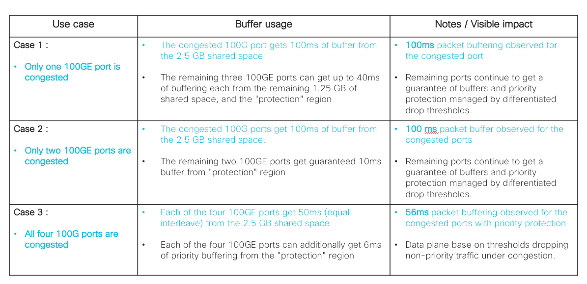
Figure 2.1 Dynamic buffer management scenarios
Static packet buffer management - fixed and chunk based
As discussed earlier, the ASR9000 4th Generation Ethernet line cards use a new high-end memory referred as HBM. Unlike with earlier commodity off-chip memories, cost considerations for the HBM memory do not allow its size to grow at the same rate as interface speeds. This motivates rethinking of static packet buffer management techniques as implemented in earlier systems. In addition to the automatic assignment of equal amount of buffer across ports, which doesn’t keep into consideration the interface actual needs, manual allocation is now possible. Manual allocation allows to customize buffer allotment to the actual port buffering demands in a specific deployment.
Automatic static buffer management techniques allocate buffers equally, on a per-port or per-port-group basis, thus exclusively guaranteeing a predefined and fixed amount of buffer memory for each port under traffic congestion. Once this buffer carving is done during NP initialization, regions allocated to different ports cannot be leveraged to relieve congestion on an affected interface.
Manual static buffer allocation ensures specific router interface the amount of queuing capacity so that it can build the guaranteed per-priority-buffer limits up to 8 priorities queuing, or budget for network oversubscription. The latter allows edge routers to be configured to absorb bursts in lieu of downstream access devices with very low buffers. Buffer allocation to a specific port is done in multiple of 10ms up to 120ms. The remaining buffer space in the HBM memory is equally divided across the remaining ports in a given NP.
The 4th Generation ASR9000 Ethernet line cards provide a configuration knob to set buffer management to static mode where required. Manual customization of packet buffer for a specific interface is done by configuring the buffer size for the port’s chunk, as shown in Figure 3.1. A “chunk” is an index that refers to the portion of HBM memory buffer space that is assigned to that port. “port” here denotes a single 100Gbps interface, or the aggregate of breakout interfaces of one 100Gbps port.
A line card can function with mix mode NPs, as different port groups may have different traffic buffering requirements.
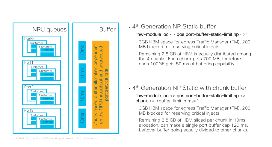 Figure 3.1 Static packet buffer management
Figure 3.1 illustrates the two options available when a user explicitly configures the NP to operate in a static buffer management mode. This mode still reserves 200 MB of HBM memory for internal ports and critical protocol protection. Therefore, only the “shared” and “protection” regions can be carved for static buffer management.
When the user configures “hw-module loc
As an example, without any specific per-chunk carving, each chunk gets 700 MB of memory, which translates to 50ms of buffering. However, if the one block is configured for 120ms buffering, the remaining three chunks will only get 35ms each.
This enhancement to static packet buffer management enables very granular control of memory allocation on each port. It better handles per priority buffer limits control of the port, so that the top priority queue can be allowed to use up to the total buffer assigned to the port, thus reducing the top priority traffic drop probability. The other priority queues (P2 to P8) share the remaining buffer using an allocation logic similar to the top priority P1’s, based on their order of priority. Furthermore, since the configuration knob is available on a per-chunk basis, it applies to different port speeds and future card variants.
Summary
This paper highlighted how the 4th generation NP on the Cisco ASR9000 product family introduces a dynamic, adaptive and on-demand architecture for packet buffering. In addition, the fallback option of static buffer management, the support for mixed mode NPs on the same line card and the enhancements of chunk-based user defined buffer carving allow for backward compatibility where needed.
Leave a Comment