ASR 9000 Inline MAP-T Border Relay Configuration and Troubleshooting
Introduction
ASR9k can act as a Border Relay MAP-T function (explained in RFC 7599) without the need of a Service Module Line Card. It is supported with 4th and 5th generation of Ethernet Line Cards. Please see the Cisco documentation for the Details and Restrictions to configure it. Each MAP-T instance creates a Policy Based Routing rule which steers the traffic from ingress service-inline interface to the CGv6 application which removes the need for ISM/VSM service module. This Tutorial will provide the step-by-step configuration and Troubleshooting approach to enable this feature and verify it is working correctly.
Scenario
In the current Example we will consider the following scenario:
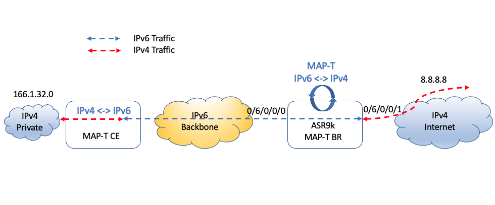
Host with IPv4 address 166.1.32.1 (port 2321) in the Private IPv4 domain needs to connect to Internet server with IPv4 address 8.8.8.8 (port 2123) through the pure IPv6 Backbone. From the connectivity perspective IP flow 166.1.32.1 <-> 8.8.8.8 will be translated twice prior (MAPT-CE) and after (MAPT-BR) IPv6 Backbone.
We will explore the ASR9k role as MAP-T Inline (no Service Modules) Border Router. MAP-T CE functionality is not considered in this Tutorial (not supported by ASR9000).
We will use 3601:d01:3344::/48 subnet to translate the Internet Host address (external domain) and 2701:d01:3344::/48 for Private host translation (CPE domain). Next section is going to explain the magic behind the translation.
Border Router Address Translation
In IPv4→IPv6 translation, destination address and port are translated based on RFC 7599 and RFC 7597 and source address on RFC 6052.
In IPv6→IPv4 translation, source address and port are translated based on RFC 7597 and RFC 7599 and destination address on RFC 6052.
Lets examine this based on IPv4 to IPv6 translation (IPv6 to IPv4 will be similar):
- Destination Address Translation (
166.1.32.1 → 2701:d01:3344::):
We need to define key numbers for Port-Mapping Algorithm (rfc7597). Based on our scenario configuration (see Configuration Section) those will be:
| Parameter | Value | Calculation |
|---|---|---|
| k | 6 | 2^k = 64 (sharing ratio) |
| m | 3 | 2^m = 8 (contiguous-ports) |
| a | 7 | 16-k-m |
| A | 512 | 2^(16-a) |
| PSID | 0x22 | Port 2321 = 100100010001 = 100100010001 (m=3) => 100100010 (k=6) |
| IPv4 Suffix | 00000001 | 32 - 24 (IPv4 prefix length) = 8 => 166.1.32.00000001 |
| EA bit | 00000001100010 | IPv4 Suffix + PSID = 8 + 6 = 14 => 00000001100010 |
| Subnet | 2 | 64 - 48 (IPv6 prefix length) - 14 (EA bits) = 2 |
| IPv6 Address | 2701:d01:3344:188:0:a601:2001:22 | IPv6 CPE suffix + EA BITS + Subnet + 16 bit 0’s + 32 bit ipv4 address + 16 bit PSID => 2701:d01:3344:00000001100010 00:0:a601:2001:22 |
Source Address Translation (
8.8.8.8 → 3601:d01:3344): This translation is more straightforward and defined by RFC 6052:/48 IPv6 prefix | v4(16) | U | (16) | suffix |
Thus final prefix will look like: 3601:d01:3344:808:8:800::
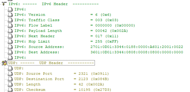
I’m using the traffic generator for this scenario and based on translations above my packets will look like:
-IPv4 to IPv6:
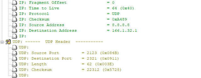
-IPv6 to IPv4:
Configuration
This is the configuration template for Inline MAP-T:
    configure
     service cgv6 instance-name
       service-inline interface type interface-path-id
       service-type map-t-cisco instance-name
         cpe-domain ipv4 prefix length value
         cpe-domain ipv6 vrf vrf-name
         cpe-domain ipv6 prefix length value
         sharing ratio number
         contiguous-ports number
         cpe-domain-name cpe-domain-name ipv4 prefix address/prefix ipv6 prefix address/prefix
         ext-domain-name ext-domain-name ipv6 prefix address/prefix ipv4-vrf vrf-name
Note: CPE V6 Prefix /64 and with V4 Prefix /24 are the best for quick testing as there are no port-sharing in that case and finding correct IP syntax is much easier (see details in the config section).
Within this tutorial we will focus on the following configuration and explain it in more details:
    configure
     service cgv6 CGV6-MAP-T
       service-inline interface TenGigE0/6/0/0/0
       service-inline interface TenGigE0/6/0/0/1
       service-type map-t-cisco MAPT-1
         cpe-domain ipv6 vrf default
         cpe-domain ipv6 prefix length 48
         cpe-domain ipv4 prefix length 24
         sharing-ratio 64
         contiguous-ports 8
         cpe-domain-name cpe1 ipv4-prefix 166.1.32.0 ipv6-prefix 2701:d01:3344::
         ext-domain-name ext1 ipv6-prefix 3601:d01:3344::/48 ipv4-vrf default
Lets verify this configuration in more details:
- Announce the cgv6 service and select the proper name:
service cgv6 CGV6-MAP-T
- Traffic coming from the interfaces configured under the service will be the subject for applying the MAP-T rules. In our example 4th generation Tomahawk Line Card is used:
	service-inline interface TenGigE0/6/0/0/0
	service-inline interface TenGigE0/6/0/0/1
- Next configure the CPE domain to specify corresponding parameters. Please mind the domain name as it will be used in troubleshooting commands:
service-type map-t-cisco MAPT-1
- Specify the CPE domain parameters:
- We can use either default or single non-default VRF for IPv6 traffic. After IPv4 to IPv6 translation, packet will be forwarded to that VRF:
cpe-domain ipv6 vrf default
- Select the prefix length both for IPv4 and IPv6. This is needed to define if additional information required for sharing-ratio and contiguous-ports which are used in port/IP translation verification (based on RFC 7599 and 7597). If IPv6 prefix length is /64 or /128 and IPv4 length is /32 then sharing-ratio and contiguous-ports will not be considered in the translation and may not to be configured. Sharing-ratio and contiguous port will define k and m values explained above.
	cpe-domain ipv6 prefix length 64
	cpe-domain ipv4 prefix length 24
	sharing-ratio 256
	contiguous-ports 8
- Finally we configure the translation rules:
- IPv4 to IPv6 rules are defined by the cpe-domain config and after translation traffic will go out of the IPv6 VRF defined above. In particular example, traffic destined to 166.1.32.0/24 subnet will be translated to
2701:d01:3344::/48subnet and send out VRF default (as configured in our example) based on the routing rule (see step 6 below):
cpe-domain-name cpe1 ipv4-prefix 166.1.32.0 ipv6-prefix 2701:d01:3344::
- IPv6 to IPv4 rules are defined based on ext-domain config. CGN will automatically derive corresponding IPv4 address from the Source and Destination addresses based on the translation algorithm. In the example below traffic towards 3601:d01:3344::/48 will find the portion of IP representing the IPv4 host and port and then route it accordingly based on the routing rule in corresponding VRF:
ext-domain-name ext1 ipv6-prefix 3601:d01:3344::/48 ipv4-vrf default
- Make sure you have Routing Entry and Adjacency for the translated addresses (otherwise traffic will be lost after translation):
"show cef 8.8.8.8"

8.8.8.0/24, version 134, internal 0x1000001 0x0 (ptr 0x721fc418) [1], 0x0 (0x721bd668), 0xa20 (0x726cd688)
 Updated Apr 27 15:08:18.684
 remote adjacency to TenGigE0/6/0/0/1
 Prefix Len 24, traffic index 0, precedence n/a, priority 3
   via 192.168.1.2/32, TenGigE0/6/0/0/1, 4 dependencies, weight 0, class 0 [flags 0x0]
    path-idx 0 NHID 0x0 [0x72a6bb08 0x0]
    next hop 192.168.1.2/32
    remote adjacency
    local label 24028      labels imposed {None}


"show cef ipv6 2701:d01:3344::"

2701:d01:3344::/64, version 10, internal 0x1000001 0x0 (ptr 0x724f27ac) [1], 0x0 (0x724bd9f0), 0x0 (0x0)
 Updated Apr 27 14:47:31.296
 remote adjacency to TenGigE0/6/0/0/0
 Prefix Len 64, traffic index 0, precedence n/a, priority 3
   via a::2/128, TenGigE0/6/0/0/0, 4 dependencies, weight 0, class 0 [flags 0x0]
    path-idx 0 NHID 0x0 [0x7344d0c8 0x0]
    next hop a::2/128
    remote adjacency
Troubleshooting
PBR
- Verifying MAP-T we first need to make sure that corresponding PBR policies have been applied correctly. First we will check the policy-map created for it automatically: “show policy-map transient type pbr”
  policy-map type pbr CGN_0
	handle:0x38000002
 	table description: L3 IPv4 and IPv6
 	class handle:0x78000003  sequence 1
   	  match destination-address ipv4 166.1.32.0 255.255.255.0
  	 punt service-node type cgn index 1001 app-id 0 local-id 0x1389
	  !
	class handle:0x78000004  sequence 1
	  match destination-address ipv6 3601:d01:3344::/48
 	 punt service-node type cgn index 3001 app-id 0 local-id 0x1b59
	  !
	class handle:0xf8000002  sequence 4294967295 (class-default)
 	  !
  end-policy-map
We can see three classes created (1 for each domain rule plus default class for non-matching traffic): 0x78000003 for IPv4 to IPv6 translation, 0x78000004 for for IPv6 to IPv4 translation and default class 0xf8000002. Missing any of the classes or not seeing proper IP addresses associated with those would mean that configuration did no apply correctly. One recommendation would be to try removing configuration for the whole instance and applying it back.
- Before we check the PBR programming we need to make sure that corresponding Null0 routes have been created for traffic Destination Addresses to be translated. That is done for PBR to be able to intercept this traffic to send further for translation. As we see from policy-map output above we need to have Null0 for prefixes 166.1.32.0/24 and 3601:d01:3344::/48. This routing entrees will be created automatically by the system:
"show route 166.1.32.0/24"

Routing entry for 166.1.32.0/24
  Known via "connected", distance 1, metric 0
  Installed Apr 27 13:49:38.809 for 00:18:05
  Routing Descriptor Blocks
    directly connected, via Null0
      Route metric is 0
  No advertising protos.


"show route ipv6 3601:d01:3344::/48"

Routing entry for 3601:d01:3344::/48
  Known via "connected", distance 0, metric 0 (connected)
  Installed Apr 27 13:49:38.904 for 00:18:21
  Routing Descriptor Blocks
    directly connected, via Null0
      Route metric is 0
  No advertising protos.
- Information from the policy-map is used further to program corresponding rules in the Hardware:
"show pbr-pal ipolicy CGN_0 detail location 0/6/CPU0"

 policy name        : CGN_0
 number of iclasses : 3
 number of VMRs     : 3
 ucode format       : 13
 vmr id for NP0     : 3
 interface count    : 2
 interface list     : Te0/6/0/0/0 Te0/6/0/0/1
"show pbr-pal ipolicy CGN_0 iclass all vmr location 0/6/CPU0"

Policy name: CGN_0
iclass handle            : 0x78000003
  ifh                    : x
  protocol               : x
  source ip addr         : x
  dest ip addr           : 166.1.32.0/255.255.255.0
  source port            : x
  dest port              : x
  DSCP                   : x
  ethertype              : x
  vlan id                : x
  vlan cos               : x
  source mac             : x
  dest  mac              : x
  packet length          : x
  result                 : 110000ac 8cc60001 65030003 e9030013 89000000 00000000 00000000 00000000
iclass handle            : 0x78000004
  ifh                    : x
  protocol               : x
  source ipv6 addr       : x
  dest ipv6 addr         : 3601:d01:3344::/48
  source port            : x
  dest port              : x
  DSCP                   : x
  ethertype              : x
  vlan id                : x
  vlan cos               : x
  source mac             : x
  dest  mac              : x
  packet length          : x
  result                 : 110000ae 8cc60001 6503000b b903001b 59000000 00000000 00000000 00000000
iclass handle            : 0xf8000002
  ifh                    : x
  protocol               : x
  source ip addr         : x
  dest ip addr           : x
  source port            : x
  dest port              : x
  DSCP                   : x
  ethertype              : x
  vlan id                : x
  vlan cos               : x
  source mac             : x
  dest  mac              : x
  packet length          : x
  result                 : 11000050 8dc60000 00000000 00000000 00000000 00000000 00000000 00000000
Make sure, that both IPv4 and IPv6 addresses are listed in corresponding VMRs. If not then verify if step (1) info above is correct and all interfaces are programmed for the Line Card (highlighted “interface list” above). Removing and re-applying service instance configuration can be helpful as well once all errors are fixed.
- Once traffic has started we can see counters in the corresponding classes (you can match the iclass id with the corresponding policy-map class to find the translation direction):
"show pbr-pal ipolicy CGN_0 iclass all stats loc 0/6/CPU0"

Policy name: CGN_0
 iclass      packets/bytes                             drop packets/drop bytes
 78000006    1494879/149487900                           0/0
 78000007    18391078/1839107800                         0/0
 f8000005    0/0                                         0/0
Seeing the counters in the corresponding classes means that PBR properly intercepted the traffic and sent it to Service Engine for Translation
Translation
Once traffic hit the correct PBR class it is being sent for translation where system will do its magic to transform the Source/Destination IP addresses and ports into the new addresses. See the “Border Router Address Translation” section above for the details. We can verify the translation counters using the counters below:
"show cgv6 map-t-cisco MAPT-1 statistics"

Map-t-cisco IPv6 to IPv4 counters:
======================================
Translated Udp Count: 76200085
Translated Tcp Count: 0
Translated Icmp Count: 0
PSID Drop Udp Count: 0
PSID Drop Tcp Count: 0
PSID Drop Icmp Count: 0

Map-t-cisco IPv4 to IPv6 counters:
======================================
Translated Udp Count: 5209786
Translated Tcp Count: 0
Translated Icmp Count: 0
PSID Drop Udp Count: 0
PSID Drop Tcp Count: 0
PSID Drop Icmp Count: 0

Map-t-cisco exception IPv6 to IPv4 counters:
======================================
TCP Incoming Count: 0
TCP NonTranslatable Drop Count: 0
TCP Invalid NextHdr Drop Count: 0
TCP NoDb Drop Count: 0
TCP Translated Count: 0
TCP Psid Drop Count: 0

UDP Incoming Count: 0
UDP NonTranslatable Drop Count: 0
UDP Invalid Next Hdr Drop Count: 0
UDP No Db Drop Count: 0
	UDP Translated Count: 0
UDP Psid Drop Count: 0

ICMP Total Incoming Count: 0
ICMP No DB Drop Count: 0
ICMP Fragment drop count: 0
	ICMP Invalid NxtHdr Drop Count: 0
ICMP Nontanslatable Drop Count: 0
ICMP Nontanslatable Fwd Count: 0
	ICMP UnsupportedType Drop Count: 0
ICMP Err Translated Count: 0
ICMP Query Translated Count: 0
ICMP Psid Drop Count: 0

Subsequent Fragment Incoming Count: 0
Subsequent Fragment NonTranslateable Drop Count: 0
Invalid NextHdr Drop Count: 0
Subsequent Fragment No Db Drop Count: 0
Subsequent Fragment Translated Count: 0

Extensions/Options Incoming Count: 0
Extensions/Options Drop Count: 0
Extensions/Options Forward Count: 0

Extensions/Options No DB drop Count: 0
Unsupported Protocol Count: 0

Map-t-cisco exception packets IPv4 to IPv6 counters:
======================================
TCP Incoming Count: 0
TCP No Db Drop Count: 0
TCP Translated Count: 0
TCP Psid Drop Count: 0

UDP Incoming Count: 0
UDP No Db Drop Count: 0
UDP Translated Count: 0
	UDP FragmentCrc Zero Drop Count: 0
UDP CrcZeroRecy Sent Count: 0
UDP CrcZeroRecy Drop Count: 0
UDP Psid Drop Count: 0

ICMP Total Incoming Count: 0
ICMP No Db Drop Count: 0
ICMP Fragment drop count: 0
ICMP UnsupportedType Drop Count: 0
ICMP Err Translated Count: 0
ICMP Query Translated Count: 0
ICMP Psid Drop Count: 0

Subsequent Fragment Incoming Count: 0
Subsequent Fragment No Db Drop  Count: 0
Subsequent Fragment Translated Count: 0

Subsequent Fragment Drop Count: 0
Subsequent Fragment Throttled Count: 0
Subsequent Fragment Timeout Drop Count: 0
Subsequent Fragment TCP Input Count: 0
Subsequent Fragment UDP Input Count: 0
Subsequent Fragment ICMP Input Count: 0

Options Incoming Count: 0
Options Drop Count: 0
Options Forward Count: 0
Options No DB drop Count: 0
Unsupported Protocol Count: 0

ICMP generated counters :
=======================
IPv4 ICMP Messages generated count: 0
IPv6 ICMP Messages generated count: 0
Normally “Translated <> Count” is incrementing when everything is good. Other specific counters will increment in case of a problem. E.G. if the traffic port is not matching the programmed port in IPv6 to IPv4 translation (as PSID is programmed into the IPv6 address):
Map-t-cisco exception IPv6 to IPv4 counters:
======================================

TCP Incoming Count: 0
TCP NonTranslatable Drop Count: 0
TCP Invalid NextHdr Drop Count: 0
TCP NoDb Drop Count: 0
TCP Translated Count: 0
TCP Psid Drop Count: 0

UDP Incoming Count: 0
UDP NonTranslatable Drop Count: 0
UDP Invalid Next Hdr Drop Count: 0
UDP No Db Drop Count: 0
UDP Translated Count: 0
UDP Psid Drop Count: 634576
NPU counters
1.Normal counters Following counters will increment during the normal work of the MAP-T translation:
"show controllers np counters np0 loc 0/6/CPU0  | ex "           0""

Read 53 non-zero NP counters:
Offset  Counter                                               FrameValue   Rate (pps)
-------------------------------------------------------------------------------------
  17  MDF_TX_WIRE                                              132257833      310077
  21  MDF_TX_FABRIC                                            132257175      310077
  33  PARSE_FAB_RECEIVE_CNT                                    132257832      310079
  45  PARSE_ENET_RECEIVE_CNT                                   312065555      310081
  53  PARSE_TOP_LOOP_RECEIVE_CNT                               558144612      620162
  70  RSV_OPEN_NETWORK_SERVICE_TRIGGER_SVC                     279072350      310081
  99  RSV_OPEN_NETWORK_SERVICE_PHASE                           279072439      310081
 544  MDF_PIPE_LPBK                                            558238357      620439
 552  MDF_OPEN_NETWORK_SERVICE_MODULE_ENTER                    558238405      620439
 556  MDF_OPEN_NETWORK_SERVICE_TRGR_FWD_LKUP                   279119214      310220
 678  VIRTUAL_IF_PROTO_IPV4_UCST_INPUT_CNT                     227572818      205272
 679  VIRTUAL_IF_PROTO_IPV6_UCST_INPUT_CNT                      50264145       21080
2010  PARSE_OPEN_NETWORK_SERVICE_SVC_LKUP                      279123639      312507
- Counters 17, 21, 33, 45 and 53 are general platform counters for traffic passing through Wire, Fabric, etc.
- Other counters are specific to PBR and Translation operations so you can match those against the rate of traffic sent in each direction. E.G. I send 200k pps of IPv6 to IPv4 flow and 100k pps of IPv4 to IPv6f flow which match the corresponding counters rate:
Offset  Counter                                               FrameValue   Rate (pps)
-------------------------------------------------------------------------------------
678  VIRTUAL_IF_PROTO_IPV4_UCST_INPUT_CNT                     227572818      205272
679  VIRTUAL_IF_PROTO_IPV6_UCST_INPUT_CNT                      50264145       21080
- Some counters may show cumulative rate as they cover both translations together. E.G.
Offset  Counter                                               FrameValue   Rate (pps)
-------------------------------------------------------------------------------------
544  MDF_PIPE_LPBK                                            558238357      620439
552  MDF_OPEN_NETWORK_SERVICE_MODULE_ENTER                    558238405      620439
556  MDF_OPEN_NETWORK_SERVICE_TRGR_FWD_LKUP                   279119214      310220
2.NP counters in case of a problem/drop
- In the Translation section above I made an example of incorrect port used in the packets not matching the IPv6 address (embedded PSID):
Offset  Counter                                               FrameValue   Rate (pps)
-------------------------------------------------------------------------------------
560  MDF_OPEN_NETWORK_SERVICE_PSID_IPV6_FAIL                     931002       12354
Counter identifies that the port used on the packets does not match the PSID programmed in the IPv6 address (see “Border Router Address Translation” above for PSID programming details). E.G. the port on the packet is “12345” and PSID is programmed based on port “2321”.
- In case of a PBR programming issue the traffic will be punted to CPU hitting the Null0 route but not intercepted by PBR (missing SERVICE related counters above):
Offset  Counter                                               FrameValue   Rate (pps)
-------------------------------------------------------------------------------------
946  PUNT_IPV6_ADJ_NULL_RTE                                        3420           2
947  PUNT_IPV6_ADJ_NULL_RTE_EXCD                                2680386        1405
- If Translation engine wont be able to define how to translate the prefix following counter will increment:
Offset  Counter                                               FrameValue   Rate (pps)
-------------------------------------------------------------------------------------
541  MDF_OPEN_NETWORK_SERVICE_PICK_UNKNOWN_ACTION             874220815       34715
- One possible scenario for it: PBR intercept packets based on destination IP address. It also going to translate the source address. Thus if that is not matching the configured entry you may see these drops. if packet source is 2701:D01:3344:4517:0:A601:2045:17 and cpe-domain rule: cpe-domain-name cpe1 ipv4-prefix 166.1.32.0 ipv6-prefix 2701:d01:3344:: As configured IPv6 prefix length is /64 than cpe-domain address not matching the packet source:
 2701:d01:3344:4517:: = 2701:d01:3344:4517:0::/64
    vs
 2701:D01:3344:0::/64
- However this is an Umbrella counter which will show up for other reasons as well. In case of unidentified problem following TECHs will be required for analysis:
show tech services cgn
show tech pbr
- Additionally it is helpful to capture and examine the packet hitting the corresponding counter. In the LAB environment it can be collected using the “monitor np counter” tool:
NOTE: This tool will have to reset the NPU upon the traffic collection completion which can cause ~150msec of traffic loss on this NPU thus its recommended to use it only in the LAB environment or during the Maintenance Window.
"monitor np counter MDF_TX_WIRE.1 np0 loc 0/6/CPU0"

Usage of NP monitor is recommended for cisco internal use only.
Please use instead 'show controllers np capture' for troubleshooting packet drops in NP
and 'monitor np interface' for per (sub)interface counter monitoring

Warning: Every packet captured will be dropped! If you use the 'count'
         option to capture multiple protocol packets, this could disrupt
         protocol sessions (eg, OSPF session flap). So if capturing protocol
         packets, capture only 1 at a time.

Warning: A mandatory NP reset will be done after monitor to clean up.
     This will cause ~150ms traffic outage. Links will stay Up.
 Proceed y/n [y] > y
 Monitor MDF_TX_WIRE.1 on NP0 ... (Ctrl-C to quit)

Tue Apr 25 20:43:20 2023 -- NP0 packet

 From Fabric: 88 byte packet
0000: ac bc d9 3e 22 22 ac bc d9 3e 71 30 86 dd 60 00   .........
0010: 00 00 00 22 2c 3f 36 01 0d 01 33 44 55 66 00 08   ...",?6...3DUf..
0020: 08 08 08 00 00 00 27 01 0d 01 33 44 45 17 00 00   ......'...3DE...
0030: a6 01 20 01 00 00 11 00 00 00 00 00 00 00 08 4b   .. ............K
0040: 09 11 00 1a 57 f0 00 01 02 03 04 05 06 07 08 09   ....Wp..........
0050: 0a 0b 0c 0d 0e 0f 10 11                           ........
Conclusion
I hope this tutorial will be helpful in building the Proof-of-Concept LAB or troubleshooting the real life scenario. It can navigate through the components used and isolate the missing/broken part. Let us know if there are any questions.
Leave a Comment