
Multicast Scaling
Multicast Scaling
Introduction
Many thanks to Anuj Budhiraja, Cisco Technical Lead Engineer, for his help writting this blog!
We have talked about Multicast before, how the technology works and the level of its complexity but we have not mentioned the way Multicast scales yet. In almost every Multicast interaction we have we get questions such as:
- What is the Multicast scale?
- How many Trees can i create?
- How do you sum all these different counters (Labels, VRFs, etc.)?
This blog will try to answer the above questions as detailed as possible and will bring to the surface how things work in regards to Multicast within IOS-XR software running on Cisco platforms.
MPLS Overview
In order to start talking about the scaling, we need to establish some basic knowledge regarding Multiprotocol Label Switching (MPLS).
MPLS is a networking routing technology that offers the ability to forward traffic based on labels, hence the name, instead of network addresses. These labels are defining the final destination of the packet and makes it much easier and more scalable for the Service Providers (SPs) to send those packets. The labels are stored in the Layer 2.
MPLS is a transport protocol and provides the benefit of bridging different sites together (full mesh). Furthermore, offers the allocation of different labels such as ToS or DSCP to the external networks and enhances the ability to support QoS and traffic prioritization.
Multicast Scaling - MPLS Transport
In the following image we can see a simple design with all types of nodes within a MPLS Transport network.
From MPLS Transport perspective we have 4 types of nodes:
- Root node: R1, it is the Source node.
- Transit/ Mid node: R2, R3, pure Transit nodes, no MVPN config.
- Bud node: R5, R6, mix of Mid/ Transit/ Leaf, can be directly connected to the Receivers.
- Leaf node: R4, directly connected to the Receivers.
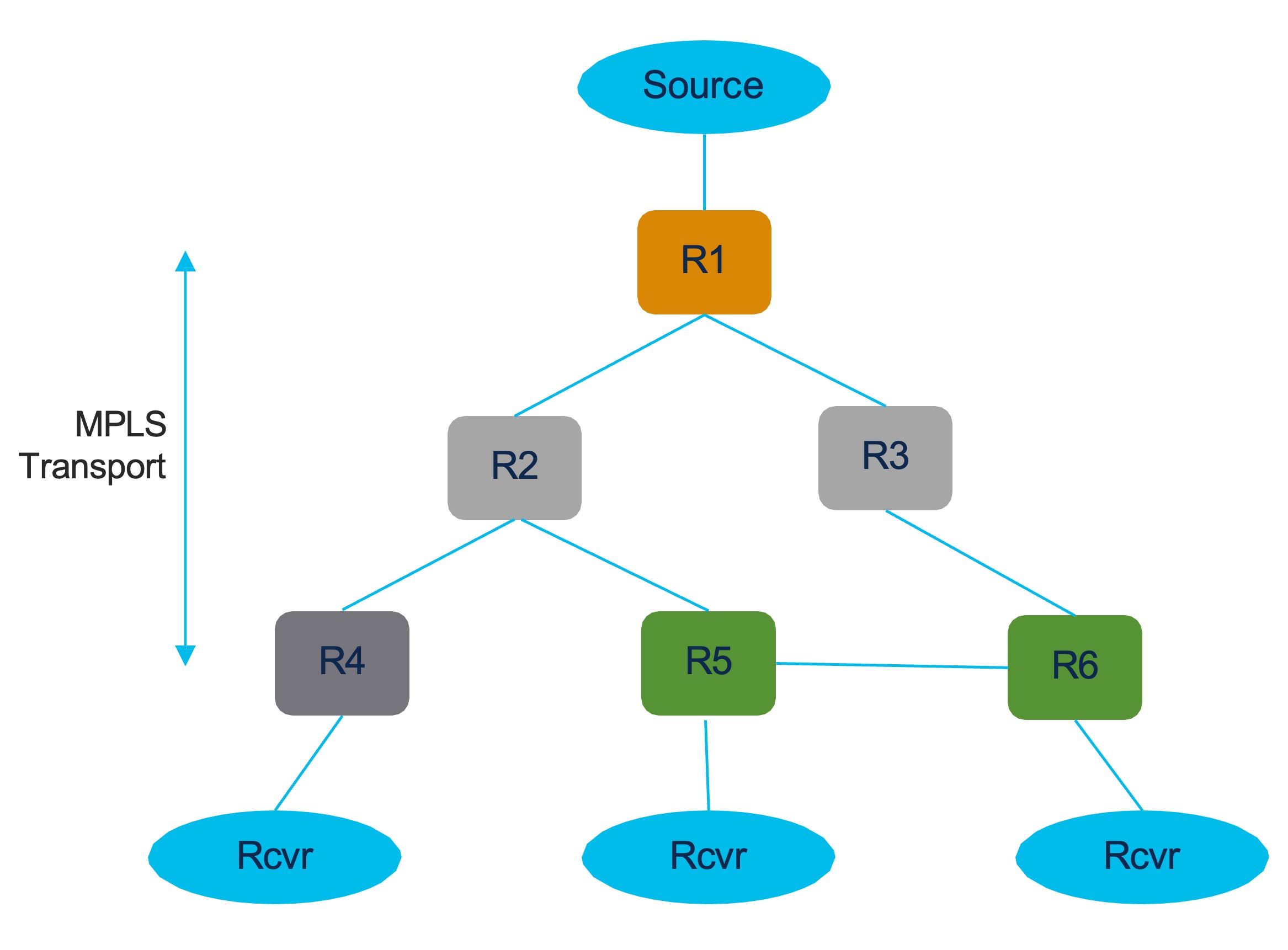
Previously we discussed about MVPN and at Cisco we have a huge variety of MVPN Profiles supported on our platforms. There are differences between Profiles when it comes to scaling, but in this blog we will mostly focus on Profile 14, because it is well known and massively deployed.
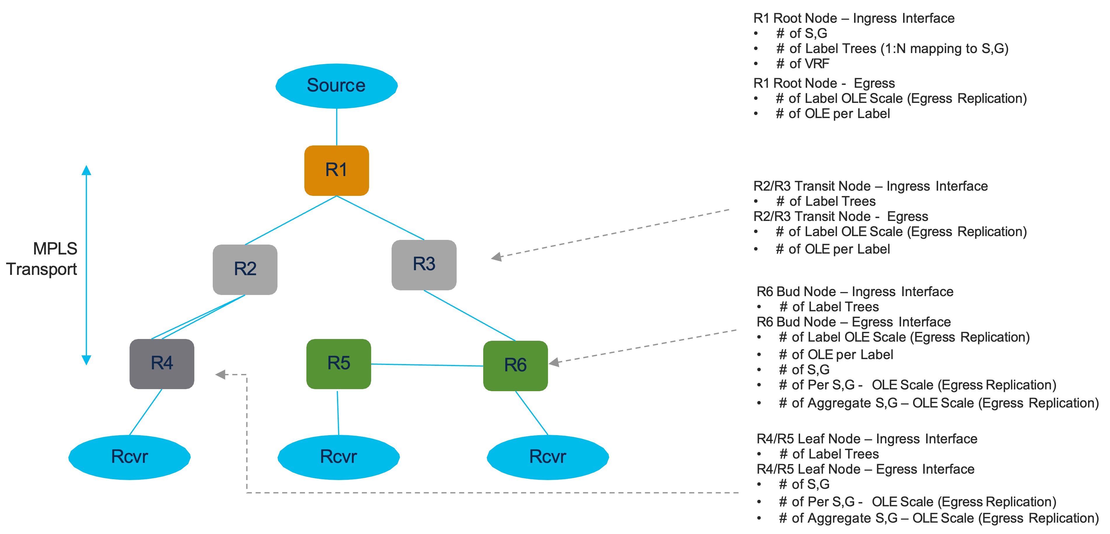
For all the above nodes there are different scale numbers that are being allocated for Profile 14. Let us define what scale numbers we get on each node.
Root node:
The Ingress traffic comes from the customer network to the service provider network and we have 3 scale numbers:
- The amount of (S, G).
- The amount of the Label Trees (MDTs).
- The amount of VRFs.
On the Egress Interface we get:
- The amount of replications per Label Tree.
Transit/ Mid node:
On the Igress Interface we get:
- The amount of the Label Trees (MDTs).
On the Egress Interface we get:
- The amount of replications per Label Tree.
Bud node:
On the Ingress Interface we get:
- The amount of the Label Trees (MDTs).
On the Egress Interface we get:
- The amount of replications per Label Tree per (S, G).
- The aggregate number of replications.
Leaf node:
On the Ingress Interface we get:
- The amount of the Label Trees (MDTs).
On the Egress Interface we get:
- The amount of replications per Label Tree per (S, G).
- The aggregate number of replications.
Resource Allocation - Example
We will list a set of steps to understand the allocation of resources to each part of the network according to the image below.
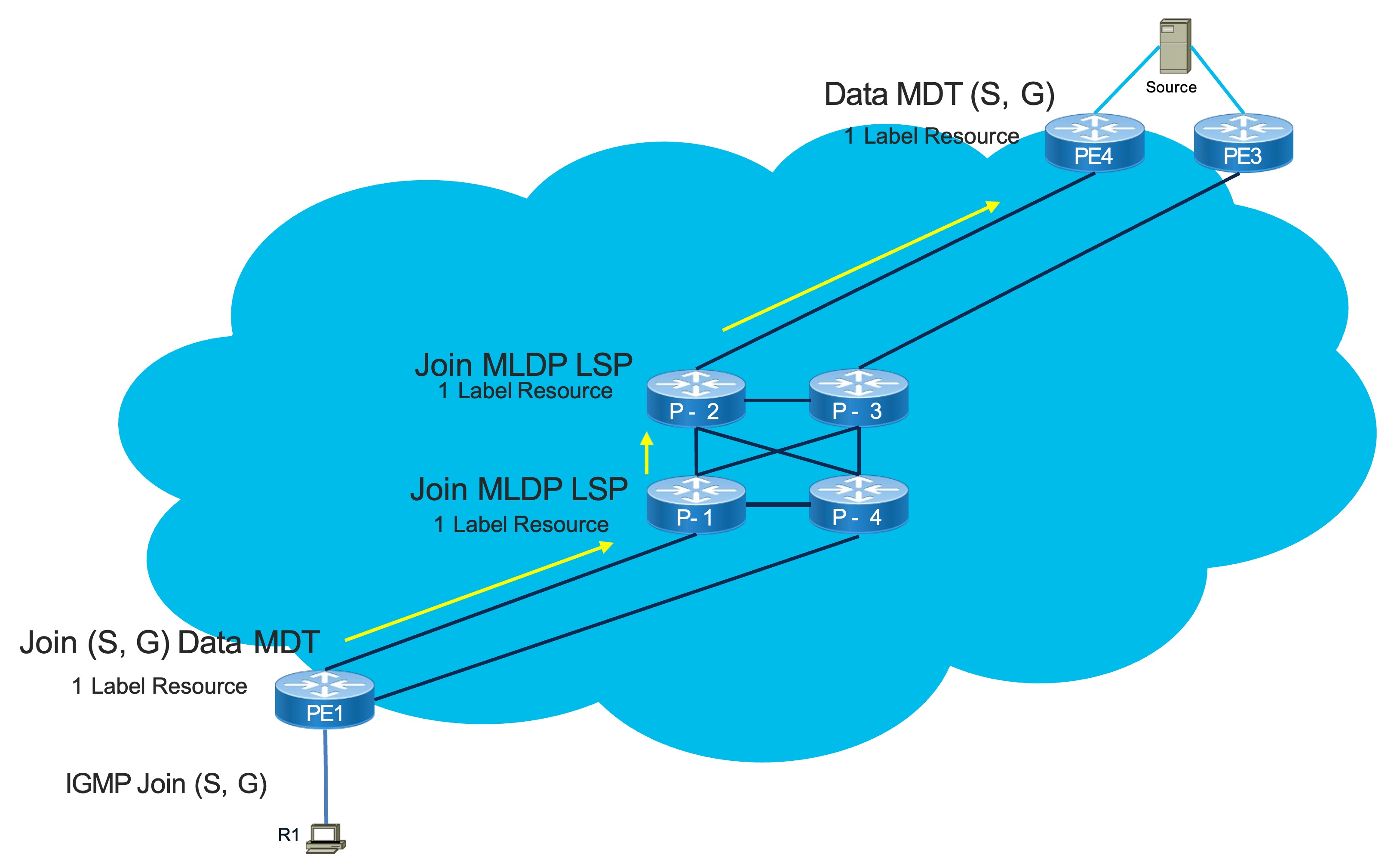
- R1 acts as a receiver and sends an IGMP Join (S, G) towards PE1.
- PE1 sends a Join in MVPN context in the form of BGP Route Type 7 for this (S, G) to PE4.
- PE4 is behind a Dual Homed Peer.
- PE4 will allocate a MDT for this (S, G).
- It consumes a Label Resource.
- PE4 will use BGP Auto Discovery Route Type 3 to send to all Ps.
- P-1 receives it and learns which Tree to join.
- PE1 will join this this Data MDT for this (S, G).
- It consumes a Label Resource.
- The Join will reach P-1 and P-1 joins the MLDP Tree.
- It consumes a Label Resource.
- P-1 sends the Join to P-2 and P-2 joins the MLDP Tree.
- It consumes a Label Resource.
- The Tree is complete.
- Despite the fact we created 1 Data MDT, 4 Label Resources were consumed.
- The purpose of the Label Resource allocation varies on each node.
Scaling Adaptation
So far we discussed how the Resources are allocated, but we understand that sometimes scaling can become tedious. There are networks that change over the time and the designs are getting replaced by new ones with updated requirements and we want to be able to comply to them as much as possible. There are situations that a platform upgrade can happen and will suffice for the new changes but there also situations that the platform has to remain the same and a redesign might be required in order to adapt to the new scaling aspects.
On the second part of the blog, we will cover one of the tools that IOS-XR can provide to us to reduce the creation of Data MDTs and therefore reduce the amount of Label Trees that are being created.
Route policy Based S-PMSI
Going back to this blog, we mentioned what Data MDT is and how/ when it can be used. Now, we will discuss about a policy that can be applied to a Data MDT.
The policy is called Based S-PMSI or named Data MDT and it is an enhanced route policy to map Multicast sources and/ or groups to a named Data MDT. It is developed to deterministically control Multicast flow mapping into Data MDT Trees. For this policy we assign names instead of numbers because they can become more descriptive.
Sample configuration:
route-policy data-mdt
	if destination in (232.0.0.0/24 1e 32) then
    	set data-mdt Red-Group-1
        pass
    endif
end-policy
The policy is able to automatically assign transport specific attributes such as MLDP FEC. The named Data MDT is created only when it matches the route policy and needs to be transitioned to Data MDT. We can create a route policy and based on its matching constraints we can put all the interested flows which we want to collect on one single Data MDT, so it can deterministically control all the Multicast Flows and map them to a single Data MDT Tree. This Data MDT will be removed if the last flow using it is removed from the Data MDT Tree.
Flow Mapping
We can have nested statements within the same route policy as well as different parameters too.
Sample configuration:
route-policy data-mdt
	if destination in (232.0.0.0/24 1e 32) then
    	set data-mdt Red-Group-1
        pass
    endif
    if source in (192.168.10.1/32) and destination in (232.0.1.0/24 1e 32) then
    	set data-mdt Red-Group-1
        pass
    endif
    if destination in (226.0.2.0/24 1e 32) then
    	set data-mdt Red-Group-2
        pass
    endif
end-policy
As we can notice, there are 2 different parameters that satisfy the “Red-Group-1” policy and there is one more parameter that satisfies a different Data MDT, “Red-Group-2”, because disparate Multicast flows can be mapped to the same named Data MDT. In addition, one policy can specify multiple named Data MDTs and only those flows mapped via one of the policies can use the named Data MDT.
Namespace Scope
Each Data MDT namespace is per Address Family/ VRF, thus named Data MDTs with the same name in distinct VRFs create distinct Data MDTs and by using same policies across VRFs will also create distinct Data MDTs. This also applies on named Data MDTs with the same name in IPv4 and IPv6 of a VRF. For example, if we create a VRF Red with Data MDT “Red-Group-1” then it will be within the scope of VRF Red and the route policy name will determine if it will be a separate Data MDT.
Sample configuration:
route-policy data-mdt-vrf-red-ipv4
	if destination in (232.0.0.0/24 1e 32) then
    	set data-mdt Red-Group-1
        pass
    endif
end-policy
route-policy data-mdt-vrf-red-ipv6
	if destination in (ff05::/96 1e 128) then
    	set data-mdt Red-Group-1
        pass
    endif
end-policy
route-policy data-mdt-vrf-green-ipv4
	if destination in (232.0.0.0/24 1e 32) then
    	set data-mdt Red-Group-1
        pass
    endif
end-policy
Conclusion
The goal of this blog was to answer commonly asked questions regarding Multicast scaling. It is understood that this topic has deeper context than just this blog but we tried to scratch the surface of it. For additional information please refer to the following links:
Multicast Distribution Trees - MDTS
Leave a Comment