
Dynamic Tree-SID + Crosswork Optimization Engine (COE)
Dynamic Tree-SID + Crosswork Optimization Engine (COE)
In previous tutorials, we discussed the fundamentals of Tree-SID as a multicast technology in IOS-XR. Today we will showcase the integration of Dynamic Tree-SID deployments with the Crosswork Optimization Engine (COE). The Crosswork team has invested time and effort to evolve the Tree-SID solution with an automated and enhanced user experience with the goal of enhancing the technology and expanding its potential.
There are 2 major challenges that we are trying to overcome:
There are 2 major challenges that we are trying to overcome:
- The lack of accurate and intuitive visibility into multicast deployments
- The effective alignment with the controller architecture
To solve the above, we need a tool to visualize and discover the multicast policies on the controller. In our case, we leverage COE and achieve operational agility with ease of visualization while providing rich automation benefits with a controller-friendly architecture.
We have the option to visualize Tree-SID topology, sessions, policies, and more in line with an automated multicast solution. In the rest of this article, we will go over screenshots from the COE dashboard and use them to visualize the configurations we have in the routers.
In the following wiki we can find configurations used in dCloud to setup this Demo.
[Shall we put the sample configs on xrdocs and link them here instead?]
The topology that will be used is shown below.
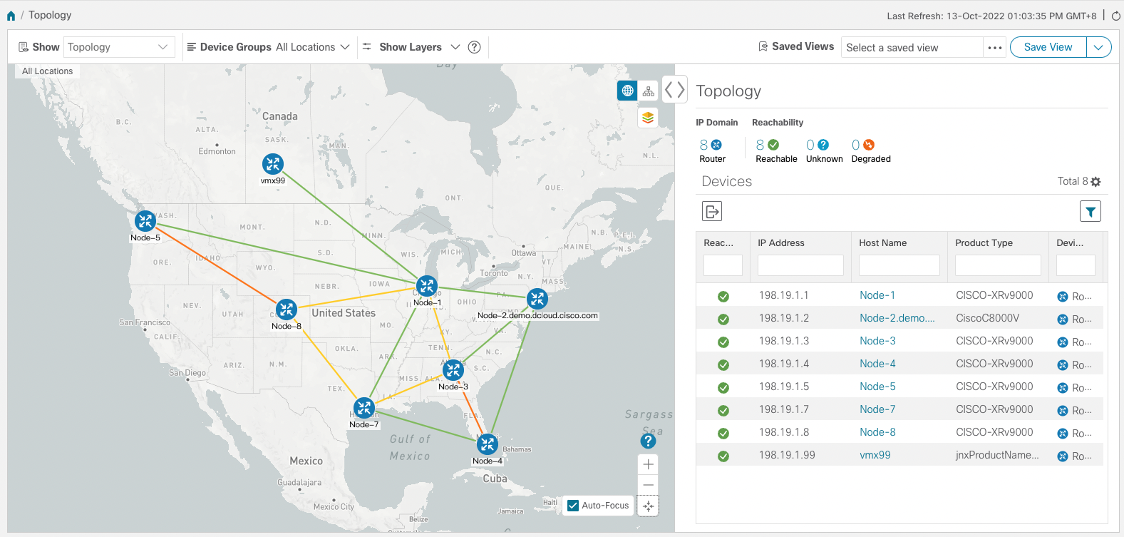
For our demonstration TreeSID topology, Node-5 is a Root node. Node-4 is a Leaf Node. Node-3, Node-7 and Node-8 are Transit Nodes. SR-PCE (xtc1) is deployed out-of-band (OOB) and is not shown in the topology.
Above nodes are IOS XRv 9000 devices.
SR-PCE Configuration
The PCE holds PCEP sessions with all the routers in the topology. We can verify that by running the following command:
Command:
show pce ipv4 peer
Output:
PCE's peer database:
--------------------
Peer address: 198.19.1.1
  State: Up
  Capabilities: Stateful, Segment-Routing, Update, Instantiation, SRv6

Peer address: 198.19.1.3
  State: Up
  Capabilities: Stateful, Segment-Routing, Update, Instantiation, SRv6

Peer address: 198.19.1.4
  State: Up
  Capabilities: Stateful, Segment-Routing, Update, Instantiation, SRv6

Peer address: 198.19.1.5
  State: Up
  Capabilities: Stateful, Segment-Routing, Update, Instantiation, SRv6

Peer address: 198.19.1.7
  State: Up
  Capabilities: Stateful, Segment-Routing, Update, Instantiation, SRv6

Peer address: 198.19.1.8
  State: Up
  Capabilities: Stateful, Segment-Routing, Update, Instantiation, SRv6
COE Dashboard of topology
The above screenshot displays all the nodes in the network that have PCEP sessions with the PCE.
Next step is to check the Tree that has been dynamically created by the PCE. The control plane has already been established and we can see the LSPs that are rooted at 198.19.1.5 (Root Node) with the corresponding Tree IDs.
Command:
show pce lsp p2mp root ipv4 198.19.1.5 | include Tree
Output:
Tree: sr_p2mp_root_198.19.1.5_tree_id_524289, Root: 198.19.1.5 ID: 524289
The next output shows the Tree structure including the Root (Ingress), the Transit nodes and the leaves (Egress) with the corresponding label ID (31000) of the Tree.
Command:
show pce lsp p2mp root ipv4 198.19.1.5
Output:
Tree: sr_p2mp_root_198.19.1.5_tree_id_524289, Root: 198.19.1.5 ID: 524289
 PCC: 198.19.1.5
 Label:    31000     Operational: up  Admin: up
 Local LFA FRR: Enabled
 Metric Type: IGP
 Transition count: 1
 Uptime: 06:10:10 (since Mon Oct 03 02:06:06 UTC 2022)
 Destinations: 198.19.1.4
 Nodes:
  Node[0]: 198.19.1.3 (Node-3)
   Role: Transit
   Hops:
    Incoming: 31000 CC-ID: 1
    Outgoing: 31000 CC-ID: 1 (198.19.1.4!) [Node-4]
  Node[1]: 198.19.1.7 (Node-7)
   Role: Transit
   Hops:
    Incoming: 31000 CC-ID: 2
    Outgoing: 31000 CC-ID: 2 (198.19.1.3!) [Node-3]
  Node[2]: 198.19.1.8 (Node-8)
   Role: Transit
   Hops:
    Incoming: 31000 CC-ID: 3
    Outgoing: 31000 CC-ID: 3 (198.19.1.7!) [Node-7]
  Node[3]: 198.19.1.5 (Node-5)
   Role: Ingress
   Hops:
    Incoming: 31000 CC-ID: 4
    Outgoing: 31000 CC-ID: 4 (198.19.1.8!) [Node-8]
  Node[4]: 198.19.1.4 (Node-4)
   Role: Egress
   Hops:
    Incoming: 31000 CC-ID: 5
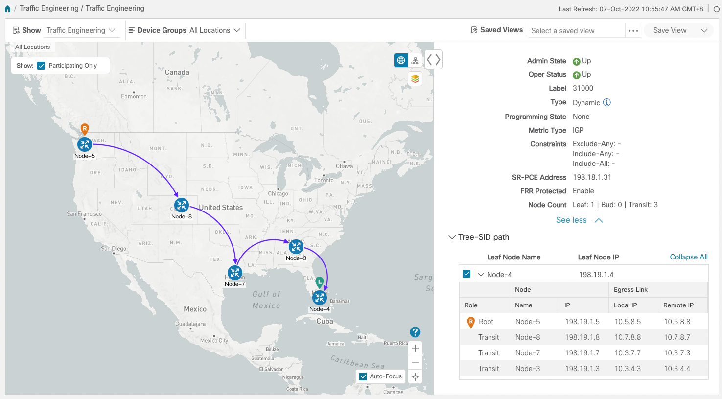
COE Dashboard of that Tree

Dashboard verifies the Tree-SID path rooted at Node-5.
All of the above conclude the configurations and outputs on PCE node (xtc1). Now we can move to the Root node.
Root node
From the root node we can get information such as VRFs, traffic-eng configurations, mvpn and segment-routing configurations
Command:
show vrf L3VPN_NM-MVPN-80
Output:
VRF                  RD                  RT                         AFI   SAFI
L3VPN_NM-MVPN-80     65000:80
                                         import  65000:80            IPV4  Unicast
                                         export  65000:80            IPV4  Unicast
COE Dashboard of that Tree
Now lets check the configuration of that specific VRF. The multicast routing for IPv4 and the bgp auto-discovery are enabled, we will use segment routing P2MP and we will allow default MDT based on P2MP SR policy. There is associated color to the default MDT.
Command:
show run multicast-routing vrf L3VPN_NM-MVPN-80
Output:
multicast-routing
 vrf L3VPN_NM-MVPN-80
  address-family ipv4
   interface all enable
   bgp auto-discovery segment-routing
   !
   mdt default segment-routing mpls color 80
   mdt data segment-routing mpls 2 color 80
  !
 !
!
COE Dashboard of that Tree
ti borw na balw edw?
There is one important thing to notice in the following command output which is the metric type IGP. Any Tree that is going to be built as part of the default or data MDT is going to be built based on that metric.
to tree eina bash igp einai te? prepei na balw kai ta dio edw?
Command:
show run segment-routing traffic-eng on-demand color 80
Output:
segment-routing
 traffic-eng
  on-demand color 80
   dynamic
    pcep
    !
    metric
     type igp
    !
   !
  !
 !
!
COE Dashboard of that Tree
ti borw na balw edw?
giati den blepw ta multicast group edW?
Below we can see the Route Type 1s for the PEs. 198.19.1.5 is the ingress PE and 198.19.1.4 is the egress PE.
Command:
show bgp vrf L3VPN_NM-MVPN-80 ipv4 mvpn
Output:
BGP VRF L3VPN_NM-MVPN-80, state: Active
BGP Route Distinguisher: 65000:80
VRF ID: 0x60000003
BGP router identifier 198.19.1.5, local AS number 65000
Non-stop routing is enabled
BGP table state: Active
Table ID: 0x0   RD version: 5
BGP main routing table version 5
BGP NSR Initial initsync version 2 (Reached)
BGP NSR/ISSU Sync-Group versions 0/0

Status codes: s suppressed, d damped, h history, * valid, > best
              i - internal, r RIB-failure, S stale, N Nexthop-discard
Origin codes: i - IGP, e - EGP, ? - incomplete
   Network            Next Hop            Metric LocPrf Weight Path
Route Distinguisher: 65000:80 (default for vrf L3VPN_NM-MVPN-80)
*>i[1][198.19.1.4]/40 198.19.1.4                    100      0 i
*> [1][198.19.1.5]/40 0.0.0.0                                0 i

Processed 2 prefixes, 2 paths
COE Dashboard of that Tree
ti borw na balw edw?
The following is the default MDT or I-PMSI. It has 1 member which is root Node 4 and there is a Tree with ID 524289.
Command:
show mvpn vrf L3VPN_NM-MVPN-80 database segment-routing
Output:
* - LFA protected MDT
Core Type      Core            Tree Core        State  On-demand
              Source           Information             Color

Default        198.19.1.5       524289 (0x80001)    Up 80
   I-PMSI Leg:      198.19.1.4
Part              0.0.0.0            0 (0x00000)  Down 80
Control           0.0.0.0            0 (0x00000)  Down 80
COE Dashboard of that Tree
ti borw na balw edw?
Now we move on to the Transit or Mid nodes.
node 3
Command:
show segment-routing traffic-eng p2mp policy root ipv4 198.19.1.5
Output:
SR-TE P2MP policy database:
----------------------
! - Replications with Fast Re-route, * - Stale dynamic policies/endpoints

Policy: sr_p2mp_root_198.19.1.5_tree_id_524289  LSM-ID: 0x40002
 Root: 198.19.1.5, ID: 524289
 Role: Transit
 Replication:
  Incoming label: 31000 CC-ID: 1
  Interface: None [198.19.1.4!]  Outgoing label: 31000 CC-ID: 1
COE Dashboard of that Tree
ti borw na balw edw?
node 7
Command:
show segment-routing traffic-eng p2mp policy root ipv4 198.19.1.5
Output:
SR-TE P2MP policy database:
----------------------
! - Replications with Fast Re-route, * - Stale dynamic policies/endpoints

Policy: sr_p2mp_root_198.19.1.5_tree_id_524289  LSM-ID: 0x40003
 Root: 198.19.1.5, ID: 524289
 Role: Transit
 Replication:
  Incoming label: 31000 CC-ID: 2
  Interface: None [198.19.1.3!]  Outgoing label: 31000 CC-ID: 2
COE Dashboard of that Tree
ti borw na balw edw?
node 8
Command:
show segment-routing traffic-eng p2mp policy root ipv4 198.19.1.5
Output:
SR-TE P2MP policy database:
----------------------
! - Replications with Fast Re-route, * - Stale dynamic policies/endpoints

Policy: sr_p2mp_root_198.19.1.5_tree_id_524289  LSM-ID: 0x40003
 Root: 198.19.1.5, ID: 524289
 Role: Transit
 Replication:
  Incoming label: 31000 CC-ID: 3
  Interface: None [198.19.1.7!]  Outgoing label: 31000 CC-ID: 3
COE Dashboard of that Tree
ti borw na balw edw?
an exei kati extra to wiki exei configurations kai outputs
Leave a Comment