
mLDP + Flex-Algo (FA)
What is Multicast Label Distribution Protocol (mLDP)
mLDP is an extension to LDP used to facilitate the transportation of multicast messages in an MPLS network. mLDP supports P2MP and MP2MP label-switched paths (LSPs). With mLDP, you can use the same encapsulation method as with the unicast messages, which reduces the complexity of the network. mLDP is a true pull-model implementation in that the PE closest to the receiver is the device to initiate the LSP.
Benefits
- Based on over 15 years of IP multicast expertise, experience, and innovation using Cisco IOS Software.
- An innovative unified control and forwarding plane that allows service providers and enterprises to transit mVPN traffic using multipoint LSPs (P2MP and MP2MP).
- State aggregation to minimize core states.
- MPLS capabilities, such as Fast Reroute, that can now be applied to multicast traffic.
- Seamless support of migration from generic routing encapsulation (GRE) and IP Multicast VPNs.
- No need to manage customer premise equipment, enable multicast routing in the core, or use link-state routing protocol extensions to support mLDP.
- Minimal cost associated with meeting bandwidth requirements of applications such as high-definition video.
- Based on industry standards.
- It is a receiver driven tree building protocol like PIM.
- mLDP uses the LDP Transport to exchange Label Mappings.
LDP Label Mapping Message
Before we move to the mLDP examples we need to understand what a LDP message is like.
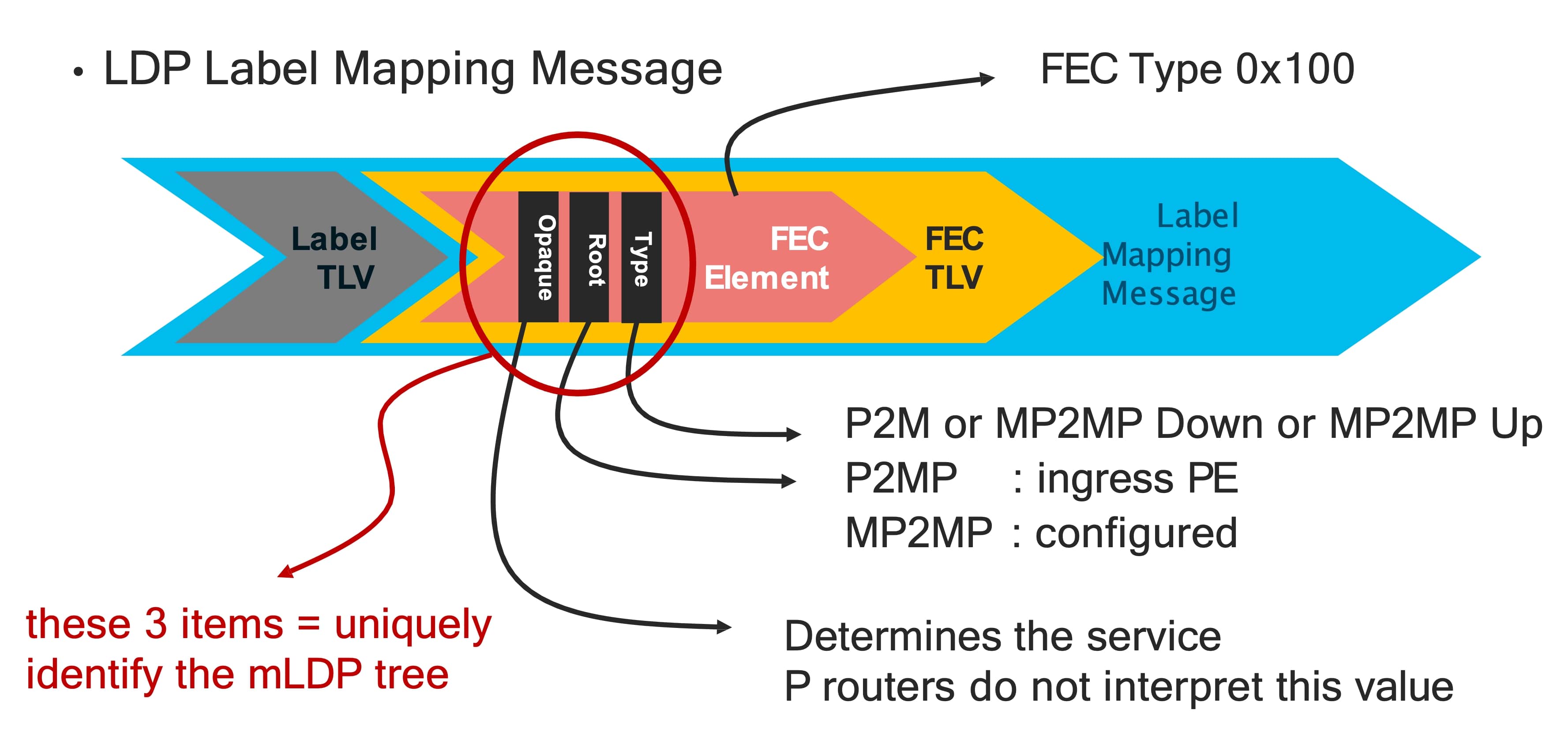
There is mLDP Label Binding and it is a FEC Type 0x100. The FEC element contains 3 things:
- Type: Point-to-Multipoint (P2M) or Multipoint-to-Multipoint (MP2MP).
- Root: There is only one Root identified by an IP address.
- Opaque: Determines the kind of multicast service (e.g. default MDT, partitioned MDT, data MDT). P routers do not interpret this value.
The above 3 items uniquely identify the mLDP tree.
mLDP signaling and packet forwarding - P2MP Tree
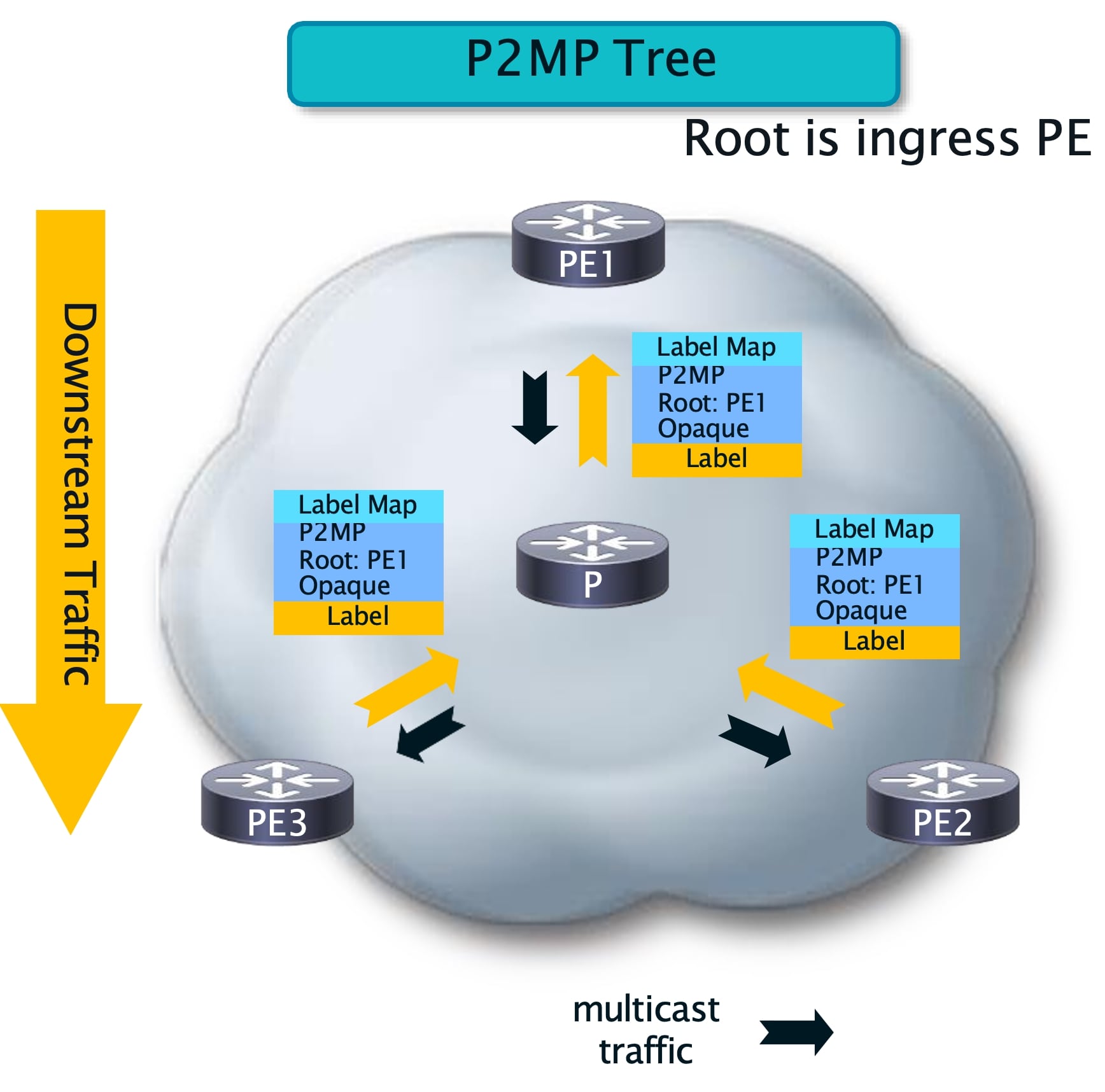
In the above P2MP scenario there are 2 receivers, PE3 and PE2 and the root PE1. The Label Mapping (LM) starts from the receiver. P3 initiaties the LM with P node and moves to the root (PE1).
The message contains the type P2MP, the root and the opaque value. There is a local label exchange between PE3 and P to receive traffic on this tree. This creates a leg from PE3 to P to PE1 and when a new receiver comes, PE2 will do the similar Label Mapping and this opaque value will remain same for the single given tree. P already has the information from the tree that was created and will simply add a branch to PE2 to join that tree. This is how the P2MP tree is created.
When traffic flows, it starts from the root downstream to the receivers which is reverse direction of the signaling and it is similar to the traditional use of PIM.
mLDP signaling and packet forwarding - MP2MP Tree
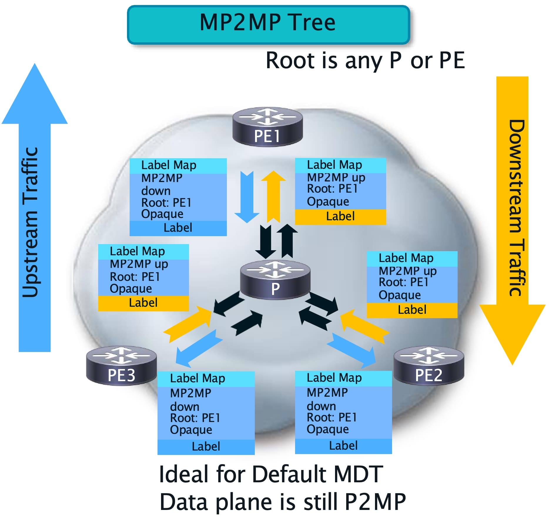
The MP2MP tree can support bidirectional traffic. It will flow from root to leaves and the opposite.
The leaf starts the signaling by sending the LM all the way up (Upstream) to the root while the opaque value remains the same. The main difference is the type in the LM which becomes MP2MP. However, in a MP2MP there will be Downstream LM starting from the root to the leaves while the opaque value carries the tree identifier. The Downstream traffic is going to flow to the reverse direction of the Upstream tree building flow but the leaves can send traffic Upstream to the root.
In the case of mLDP, the tree root for P2MP will be the ingress PE while for MP2MP tree the root is any P or PE. In a scenario that LDP is not needed because of SR MPLS, unicast LDP will be off but LDP will be turned on only for multicast.
Multicast LDP with transport differentiation using SR Flex-Algo
In this section mLDP with Traffic Engineering (TE) will be covered. So far it is known that mLDP works with basic IGP metrics but by using a different transport, SR Flex-Algo it can be enhanced to use custom constraints and metrics.
SR Flex-Algo (FA)
SR FLex-Algo is a complement solution for SRTE that adds new Prefix-Segments with specific optimization objective and constraints such as:
- minimize igp-metric or delay or te-metric.
- avoid SRLG or affinity.
It makes it possible to define different constraints and segment the network in multiple parts which results in a network which is defined by different segments. Also it leverages SRTE benefits of simplicity and automation such as:
- Automated sub-50msec FRR (TILFA).
- On-Demand Policy (ODN).
- Automated Steering (AS).
FA + Unicast
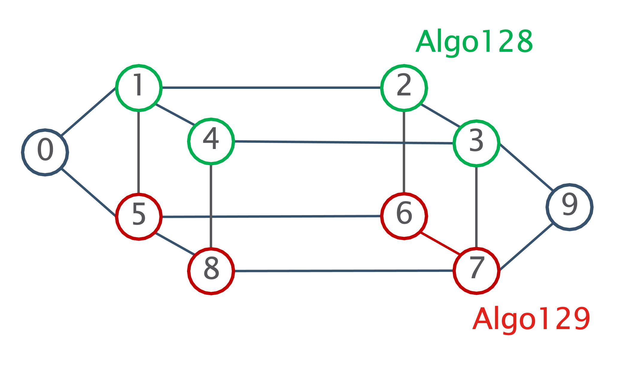
FA gives the ability to segment the network into different planes.
In the following example there are 3 groups of nodes:
- Nodes 0 and 9 participate to Algo0, Algo128 and Algo129.
- Nodes 1/2/3/4 participate to Algo0 and Algo128.
- Nodes 5/6/7/8 participate to Algo0 and Algo129.
It provides a virtual segmentation of the network with 2 planes, one green and one red. Each node must advertise which FA it belongs to.
FA aware mLDP
Let’s see how mLDP can work with FA. Originally mLDP is used to build the network tree. However, FA gives the option to create multiple trees by influencing the path computation by associating metrics and constraints within the same network. This is done to enable a new list of use cases.
Some of the use cases:
- Disjoint Trees (Dual plane): In the scenario of Disjoint Trees we can achieve segmentation of the traffic in the same network. We might want to avoid specific links, paths due to security reasons.
- Live-Live: We might have critical traffic that we want to carry it through different paths and leverage the Live-Live scenario. Later, We can define which path the traffic should follow.
- Low latency routing: We might want to achieve low latency routes for real-time, latency-sensitive activities.
All of the above use cases are possible by adding the flexible metrics and constraints.
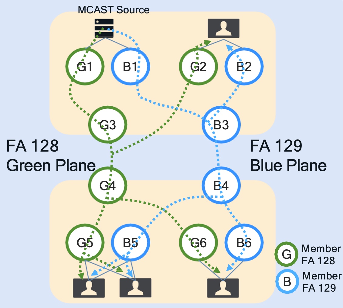
In the following example we have 1 multicast source, 5 receivers and 2 planes, green and blue. There is the slicing of the traffic between the 2 different planes but we can see that the source is able to send traffic to both planes.
BGP + FA
Let’s talk about BGP mVPN discovery. These routes carry a P-MSI tunnel attribute (PTA) and the FEC is carried in the PTA.
Reminder: FEC is the opaque value that is being use to create the underlay tree.
Also, within PTA there is the IGP Algorithm (IPA) field that carries the SR Flex Algo instance ID and that helps the egress PE to start building the underlay tree with the appropriate FA underlay.
FA + IOS-XR
Today in IOS-XR we support the following:
- mVPN profile 14 - partitioned MDT mLDP P2MP with BGP-AD and BGP c-mcast signaling.
- mVPNv4/ mVPNv6 overlay.
- Partitioned and data MDTs.
- Granular mapping of (C-S, C-G) to a partitioned MDT/ data MDT bound to a FA instance.
- PIM ASM, SSM, IGMPv2 and IGMPv3 as customer access protocols.
- ECMP - A FA topology may have ECMP and therefore multicast flows are load balanced if multiple paths are available.
mLDP signaling with FA (How operation works)
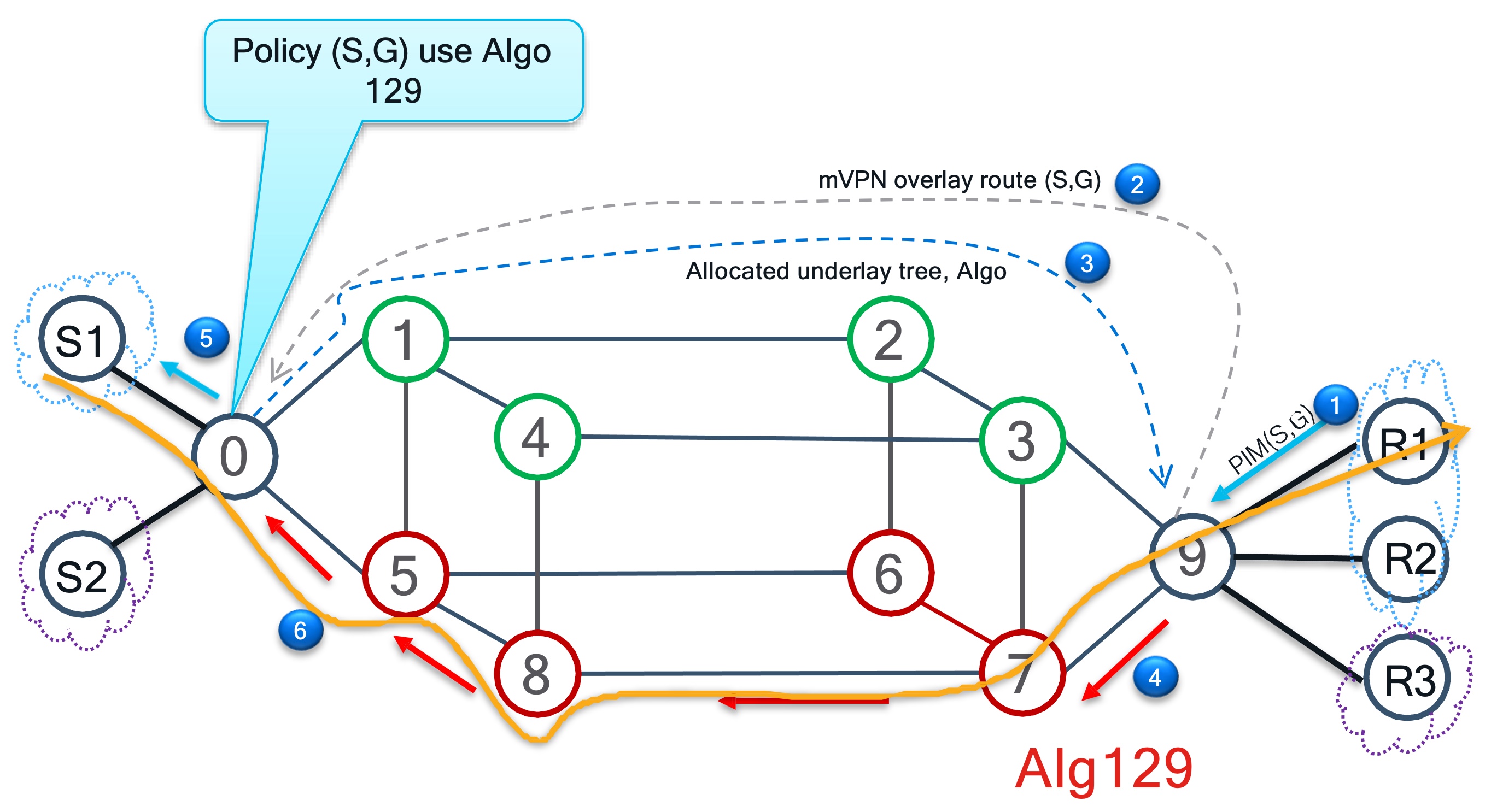
The following is an example of mLDP signaling with FA. The operation is split into 6 steps and works like this:
There are 2 VRFs, blue and purple. S1 is the source and R1, R2 are the receivers for the blue VRF while S2 is the source and R3 the receiver for the purple VRF. Routers 0 and 9 are the edge devices, P nodes, meaning that all the overlay signaling will take place between them and the underlay tree will be built using the core network. We can see that R0 has a (S, G) policy with Algo129. R0 is linked to S1 therefore any request that carries the same policy will go over red plane (Algo129).
Step 1: The membership request can either be PIM Join or IGMP Join in case the receivers are directly connected.
Step 2: To analyze mVPN signaling we look where the source is and the source is behind R0. So R9 sends Join overlay to R0 for this particular VRF. Once R0 receives it, it is going to look at the policy for the following:
- Where exactly this traffic has to come from
- Where the underlay tree has to be created..
Step 3: This tree has to be created using Algo129, so it is going to allocate a tree which can be partioned MDT or data MDT and it is going to signal back to R9 saying that if you want to build a tree you need to use Algo129 which is defined in the policy.
Step 4: R9 starts building the underlay multicast tree for this FEC by sticking to policy Alg129.
Step 5: Eventually the Join is received by the actual source VRF, S1.
Step 6: S1 starts flowing the traffic through the red plane.
It is important to understand that the network is now separated which makes red plane totally independent by green plane. Anything that might happen within the red plane such as failure, it will be taken care by the current plane and will be containted in it without interfering with the other planes. Whatever happens between 5,6,7,8 will never be linked to the green plane.
Leave a Comment