
NCS5500 QoS Part 1 - Understanding Packet Buffering
You can find more content related to NCS5500 including routing memory management, VRF, URPF, ACLs, Netflow following this link.
Introduction to Packet BUFFERING
This first blog post will help understanding key concepts on the buffering architecture and clarify things like VOQ-only, single-lookup and ingress-buffering only designs.
It’s necessary to detail all these mechanisms to understand later the subtleties of the QoS implementation, including the scales and limitations.
Video
The short version of this article is available in the following Youtube video:
https://www.youtube.com/watch?v=_ozPYN6Ej9Y
DNX ASICs in NCS5500 family
All the NCS5500 routers are powered by Broadcom StrataDNX (or DNX) Network Processor Units (NPUs).
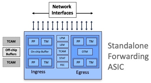
These ASICs can be used in standalone mode (Systems on Chip):
or interconnected through one or multiple Fabric Engines:
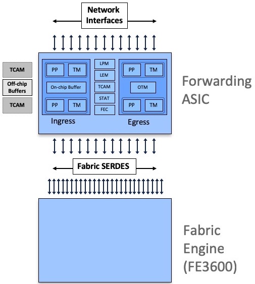
All Jericho and Qumran options are following a very similar architecture, they are using resources inside the ASIC (packet memory, routing information memories, next-hop memories, encapsulation memories, statistics memories, etc etc) and also external to the chipset (like the DRAM used for packet buffering).
Some systems are equipped with external TCAMs or not, that’s how we differentiate base and scale systems/LCs.
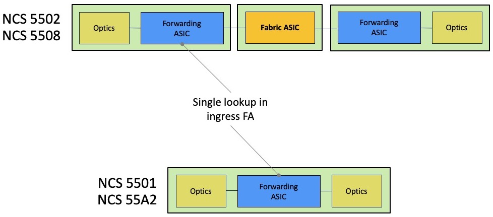
On the Jericho side:
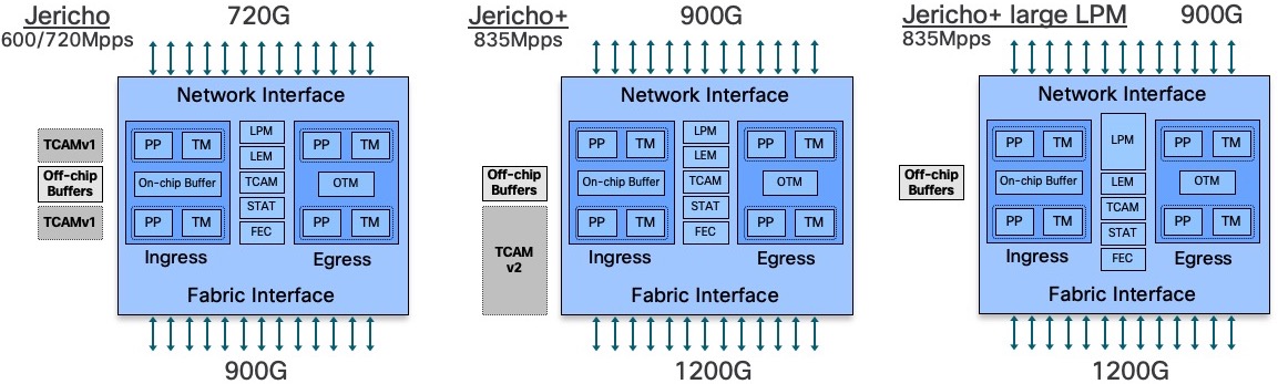
- Jericho ASICs are used in NCS5502, NCS5502-SE, and in following line cards: NC55-36X100G, NC55-24H12F-SE, NC55-24X100G-SE, NC55-18H18F, NC55-6X2H-DWDM, NC55-36X100G-S
- Jericho+ (with “normal LPM”) ASICs are used in NCS55A1-36H-S, NCS55A1-36H-SE-s, all NCS55A2-MOD-xx and in following line cards: NC55-36X100G-A-SE, NC55-MOD-A-S, NC55-MOD-A-SE-S
- Jericho+ with large LPM is used in NCS-55A1-24H
On the Qumran side:
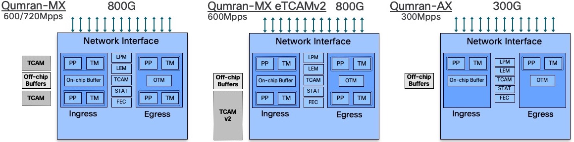
- Qumran-MX is used in NCS5501 and NCS5501-SE
- Qumran-MX with 2nd generation eTCAM (OP) is used in the scale version of RSP4 / NCS560
- Qumran-AX is used in the N540-24Z8Q2C-SYS
DNX ASICs architecture
All the DNX forwarding ASICs used in the NCS550 portfolio are made of two cores (actually, only the Qumran-AX used in NCS540 is single core), and they are all made of an ingress and an egress pipeline.
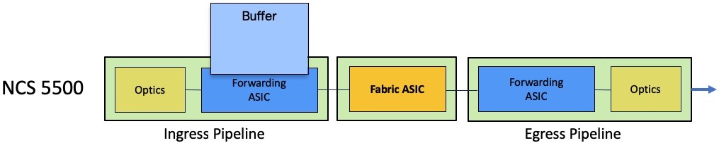
A packet processed in the forwarding ASIC will always be received in the ingress pipeline handling the receiving port and via the egress pipeline of the outgoing port, could it be in the same NPU or in different NPUs (connected through a fabric engine).
A big difference, compared to our tradition routers based on run-to-completion architectures, is the fact we will only perform a single-lookup in ingress to figure out the destination of a received packet. So, this operation will happen in the ingress pipeline only.
It will reduce the latency and globally will improve the performance.
But it has significant implications on the packet buffering too. Indeed, the buffering in egress side will be minimal and in case of queue or port congestion, the packets will be stored in ingress. That also implies an advanced mechanism of request/authorization between arbitrators.
That’s what we will describe now.
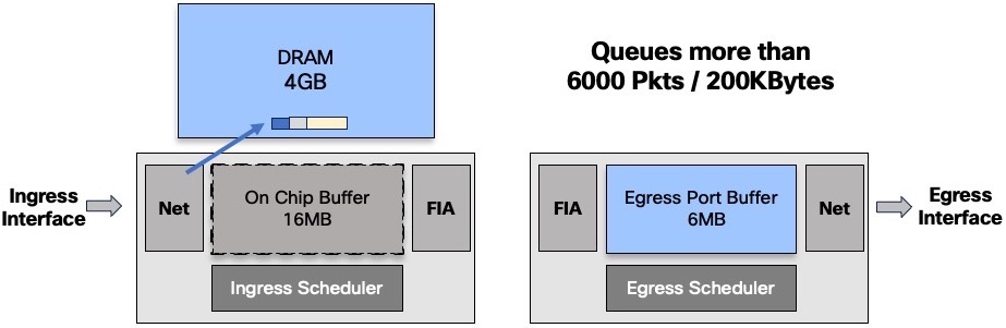
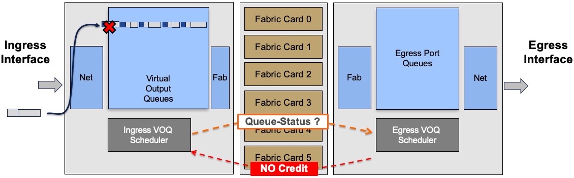
Ingress-only buffering
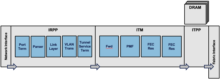
Every packet received in the ingress pipeline will go through multiple stages. Each pipeline block has a specific role and a budget of resource access (read and write). The FWD block will be responsible for the packet destination lookup. That’s where the routing decision is made and it will result in pointers to next-hop information and header encapsulation (among other things).
Once the destination is identified, the packet is associated to a queue (a VOQ more precisely) but we will come back on this concept below.
The ingress scheduler will contact its egress counterpart and will issue a packet transmission request:
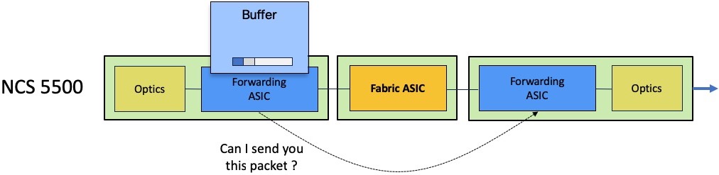
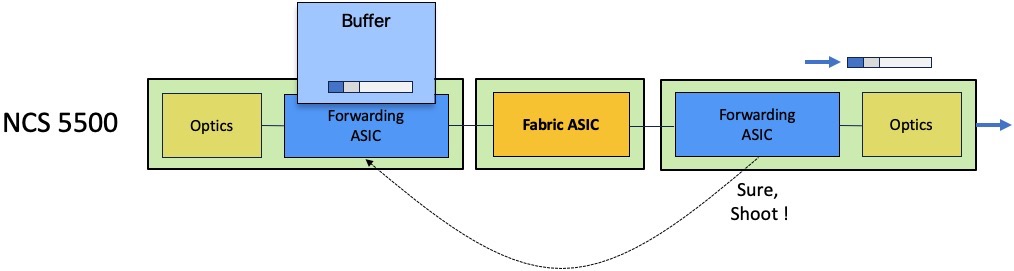
The egress scheduler will accept or refuse this request depending on the queue availability.
If the queue is congested, the egress scheduler will not provide token for transmission and the packet will be stored in the ingress packet memories.
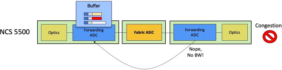
Depending on the level of queue congestion, the packet will be stored inside the NPU or in the external DRAM. Once the congestion state disappears, the egress scheduler will be able to issue the token for the most critical queue. The QoS configuration will dictate this behavior. If QoS is not configured, the First In First Out rule will apply.
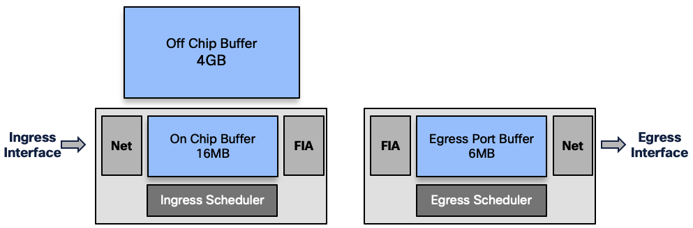
So the packets are buffered in different places along the path:
- (ingress) On-chip Buffer: 16MB or
- (ingress) external DRAM: 4GB
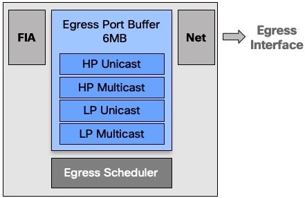
- (egress) Port Buffer: 6MB
For a given queue, packets are stored in OCB or DRAM.
The decision to keep a queue in OCB or to evict it to the DRAM will depends on the numbers of packets buffered:
- below 6000 packets or 200k Bytes, the queue will stay inside the chipset
- above one of these two thresholds, the packets are stored in DRAM
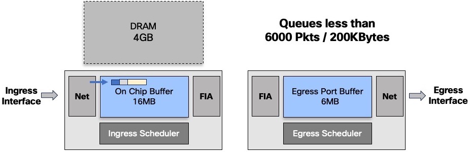
This management is done at the queue level only. It will not impact the other packets going to other destination or even to the same destination but in a different queue:
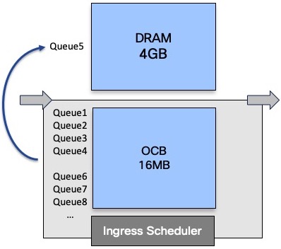
As long as we have packets in this evicted queue, it will stay in the DRAM. Once emptied, the queue is moved back to internal buffer.
On the egress side, we have a 16MB memory used to differentiate unicast and multicast traffic, and among them to separate high and low priority. That’s the only level of classification available on the output buffer.
In the future we will come back on the main difference of behavior between unicast and multicast, in a VOQ-only model.
Virtual Output Queues
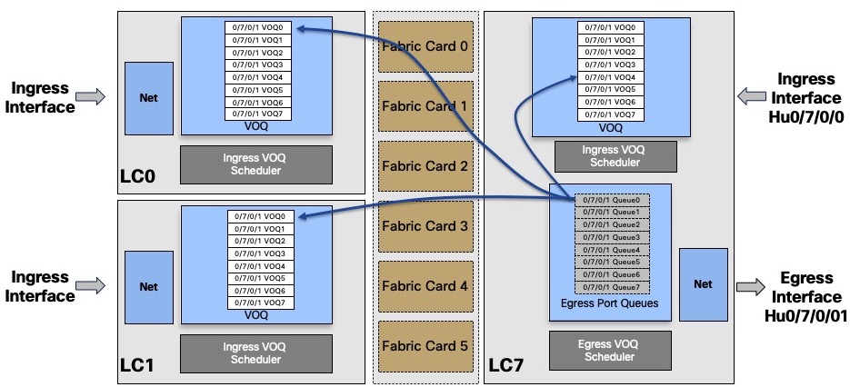
Contrary traditional platforms in our SP portfolio (ASR9000, CRS, NCS6000, …), the packets are not stored in the output queues in case of congestion.
In the NCS5500 world, we are creating a virtual representation of the egress queues on the ingress side.
Indeed, everytime a packet needs to be sent to a remote point but is not given the right to be transmitted to an egress pipeline, it will be stored in the ingress buffer (could it be inside the NPU or in the DRAM).
These are our famous “Virtual Output Queues”.
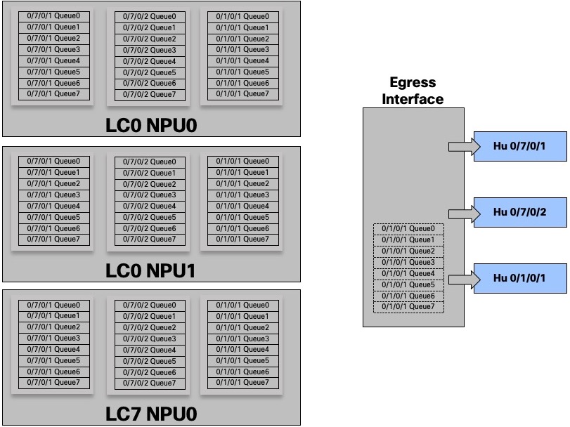
For a given egress port or “attachment point”, we have 8 queues in each ingress NPU.
In this example, the egress port HunGig0/7/0/1 is materialized by 8 queues in EACH ingress NPU
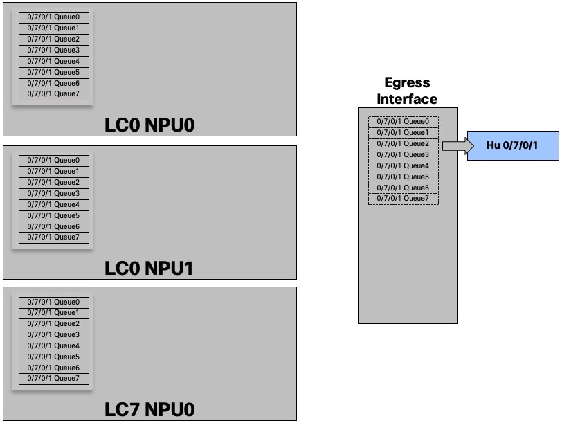
And for three interfaces:
With this show command, we take the perspective of the NPU 0 on Line Card 1, the queue is seen as remote.
RP/0/RP0/CPU0:R1#sh contr npu stats voq ingress interface hu 0/7/0/1 instance 0 location 0/1/CPU0

Interface Name    =    Hu0/7/0/1
Interface Handle  =      3800118
Asic Instance     =            0
VOQ Base          =         1328
Port Speed(kbps)  =    100000000
Local Port        =       remote
       ReceivedPkts    ReceivedBytes   DroppedPkts     DroppedBytes
-------------------------------------------------------------------
COS0 = 0               0               0               0
COS1 = 0               0               0               0
COS2 = 0               0               0               0
COS3 = 0               0               0               0
COS4 = 0               0               0               0
COS5 = 0               0               0               0
COS6 = 0               0               0               0
COS7 = 0               0               0               0
RP/0/RP0/CPU0:R1#
It represents the number of packets received on NPU0 LC1 and targeted to HundredGig 0/7/0/1 queues.
COS0 represents the default queue.
But the queues also exist locally on the same NPU of the same line card, from an ingress pipeline perspective.
In the following output, we see that the queues are seen as local from the NPU 0 LC 0/7 perspective which indeed handles HunGig0/7/0/1
RP/0/RP0/CPU0:R1#sh contr npu stats voq ingress interface hu 0/7/0/1 instance 0 location 0/7/CPU0

Interface Name    =    Hu0/7/0/1
Interface Handle  =      3800118
Asic Instance     =            0
VOQ Base          =         1328
Port Speed(kbps)  =    100000000
Local Port        =        local
       ReceivedPkts    ReceivedBytes   DroppedPkts     DroppedBytes
-------------------------------------------------------------------
COS0 = 0               0               0               0
COS1 = 9               1107            0               0
COS2 = 0               0               0               0
COS3 = 0               0               0               0
COS4 = 0               0               0               0
COS5 = 0               0               0               0
COS6 = 0               0               0               0
COS7 = 139289          28863790        0               0
RP/0/RP0/CPU0:R1#
It represents the number of packets received on NPU0 LC7 and targeted to HundredGig 0/7/0/1 queues, in the same ASIC.
Even if the packets destination is located in the same NPU, it will follow the same rules of request / grant to get the right to transmit.
In such case, the packets will not transit through the fabric but still, they will be split in cells. They will take an internal path inside the ASIC. It’s also what happens when using a System on the Chip (NCS5501, NCS55A2-MOD, …).
Each ingress NPU links the local VOQ to the output queues via a “flow connector”.
DRAM capacity and Bandwidth to DRAM
Each NPU is associated to a 4GB DRAM. It’s not a removable part, it’s not an option. All products in the NCS5500 family are following this rule.
This memory is important but is not used most of the time.
We will demonstrate in next article that the percentage of packets going to DRAM represents a tiny portion of the overall traffic (around 0.15%).
The NPU is connected to the DRAM via a 900Gbps unidirectional link:
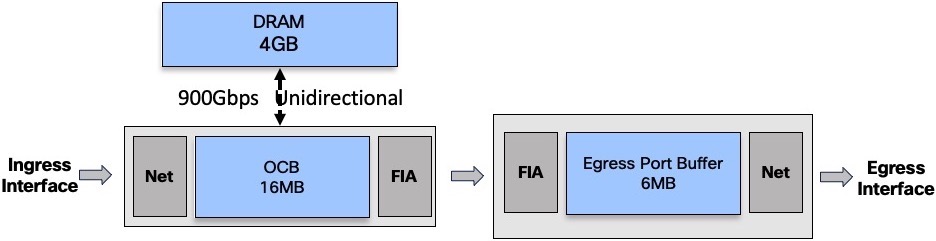
Unidirectional means we can:
- write in the DRAM at 900Gbps
or - read in the DRAM at 900Gbps
or - read at 700Gbps and write at 200Gbps
If we maintain a constant state of queue eviction (all the queues are constantly receiving traffic and can’t be moved back to OCB), we end up with a 450/450 state:
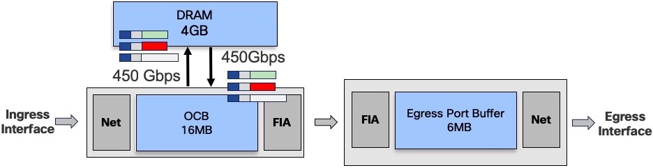
To reach such a situation, we need very specifically crafted traffic flows, maintaining a constant state of saturation without being taildropped (check the next section).
Aside in a lab, having traffic received on a given NPU and targeted all the queues of all the egress ports while maintaining a congestion state, is not a realistic scenario.
It’s important to keep in mind we are increasing the amount of DRAM and the total amount of bandwidth to this DRAM when we insert more line cards (more NPUs) in a system:
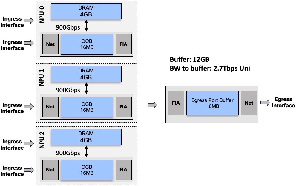
In this example, we have 3 NPUs, representing a total of 12GB of traffic and an aggregated bandwidth of 2.7Tbps unidirectional to the external buffer.
More line cards –> more NPUs –> more DRAM and more bandwidth to DRAM.
Taildrop
By default a given queue is given 10ms of the overall interface capacity (concept of queue-limit). Please note, it’s not a guaranteed amount of buffer, actually it represents the maximum a queue can be given by default. Above that level, the queue will start dropping new packets.
The max size of a queue can be changed by configuration as shown below where qos3 is modified from default to 20ms:
RP/0/RP0/CPU0:NCS5508(config)#policy-map egress-policy
RP/0/RP0/CPU0:NCS5508(config-pmap)# class qos2
RP/0/RP0/CPU0:NCS5508(config-pmap-c)#queue-limit 20 ?
  bytes    Bytes
  kbytes   Kilobytes
  mbytes   Megabytes
  ms       Milliseconds
  packets  Packets (default)
  us       Microseconds

RP/0/RP0/CPU0:NCS5508(config-pmap-c)#queue-limit 20 ms
RP/0/RP0/CPU0:NCS5508(config-pmap-c)#commit
RP/0/RP0/CPU0:NCS5508(config-pmap-c)#

RP/0/RP0/CPU0:NCS5508#sh qos int hu 0/0/0/0 output
NOTE:- Configured values are displayed within parentheses
Interface HundredGigE0/0/0/0 ifh 0x130  -- output policy
NPU Id:                        0
Total number of classes:       4
Interface Bandwidth:           100000000 kbps
VOQ Base:                      1192
Accounting Type:               Layer1 (Include Layer 1 encapsulation and above)
------------------------------------------------------------------------------
Level1 Class (HP1)                       =   qos1
Egressq Queue ID                         =   1193 (HP1 queue)
Queue Max. BW.                           =   0 kbps (20 %)
TailDrop Threshold                       =   125304832 bytes / 10 ms (default)
WRED not configured for this class

Level1 Class                             =   qos2
Egressq Queue ID                         =   1194 (LP queue)
Queue Max. BW.                           =   50901747 kbps (50 %)
Queue Min. BW.                           =   0 kbps (default)
Inverse Weight / Weight                  =   1 / (BWR not configured)
TailDrop Threshold                       =   2506752 bytes / 20 ms (20 ms)
WRED not configured for this class

Level1 Class                             =   qos3
Egressq Queue ID                         =   1195 (LP queue)
Queue Max. BW.                           =   30247384 kbps (30 %)
Queue Min. BW.                           =   0 kbps (default)
Inverse Weight / Weight                  =   1 / (BWR not configured)
TailDrop Threshold                       =   1253376 bytes / 10 ms (default)
WRED not configured for this class

Level1 Class                             =   class-default
Egressq Queue ID                         =   1192 (Default LP queue)
Queue Max. BW.                           =   101803495 kbps (default)
Queue Min. BW.                           =   0 kbps (default)
Inverse Weight / Weight                  =   1 / (BWR not configured)
TailDrop Threshold                       =   1253376 bytes / 10 ms (default)
WRED not configured for this class
RP/0/RP0/CPU0:NCS5508#
If a queue is completely saturated, the packets are taildropped. That means the NPU will discard them without trying to push them to the DRAM / External memory, freeing the unidirectional bandwidth detailed above.
HOLB?
The problem of head of line blocking experienced by some routers in the past is not present with current architecture where any unicast packet is scheduled. A transmission can only happen if the egress scheduler/arbitrator provided a token to the ingress side. Therefore, a saturated queued will have no impact on the other queues, even on the same port.
In this example, the two queues represented by packets in grey are targeted to interface 1, saturated. It will not prevent the egress scheduler for interface 2 to provide authorization to transmit to the packet in green:
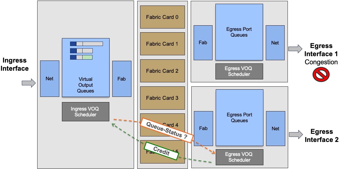
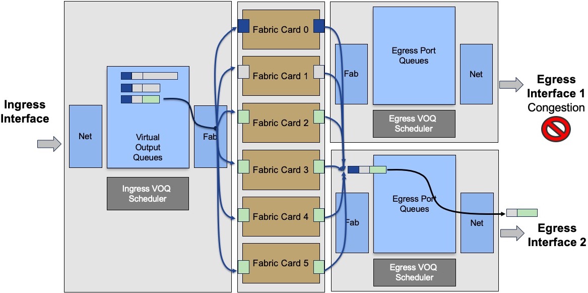
The communication between ingress and egress scheduler is going through the fabric via a protected/priviledge path.
Next episode
In part 2, we will demonstrate in a large test bed how the buffer works and we will check in production routers how many packets are handled by OCB or DRAM.
Leave a Comment