
Introducing NCS57C3-MOD Routers
This article has been written and reviewed by (in alphabetical order):
- Akshaya Kumar Sankaran, TME
- Amit Kumar Dey, PM
- Nicolas Fevrier, TME
- Paban Sarma, TME
- Tejas Lad, TME
- Vincent Ng, TME
Update 1 (12 Oct 2021): fixed an error in the 1G scenario, MPA slot 2 and 3 don’t support 1G ports on the 12T MPA.
Introduction
With IOS XR 7.4.1, we introduced multiple software features (https://xrdocs.io/ncs5500/tutorials/iosxr-741-innovations/) but new hardware are also launched with this release. We are very happy to introduce a new member to the NCS5500 family, the NCS57C3-MOD series.
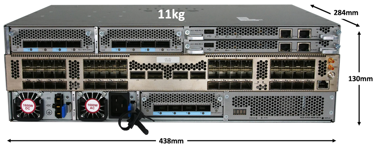
These two new routers are the NCS-57C3-MOD-SYS and NCS-57C3-MODS-SYS, that can be considered the successors of NCS55A2-MOD. They are built following the same philosophy:
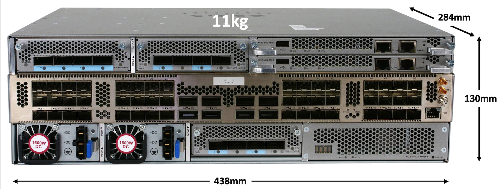
- compact form-factor (less than 300mm deep and 3RU here)
- offering the highest level of flexibility with both fixed SFP and QSFP ports (1G, 10G, 25G, 40G, 100G)
- modular port adaptors
but also new goodies are specific to this NCS57C3-MOD: - much higher forwarding capability (2.4Tbps compared to 900G on NCS55A2-MOD)
- dual RP for control plane redundancy
- 3x MPA (two at 800G and one at 400G)
They can be used in multiple places in the network: aggregation, pre-agg, 5G (class-C capable), internet peering, core, enterprise…
Videos
.
Understanding the naming logic
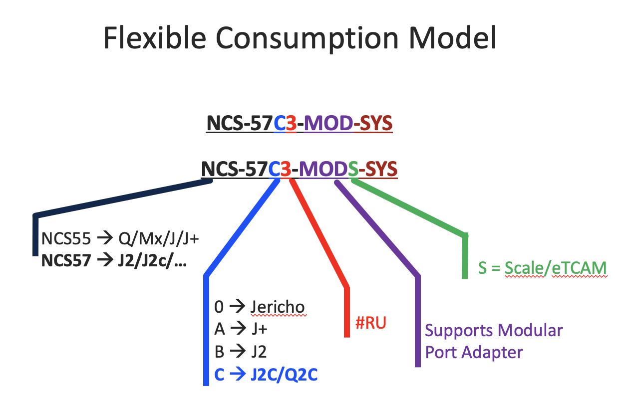
The name of the product is different depending on the licensing model used.
With Flexible Consumption Model:
- NCS-57C3-MOD-SYS is the “base” version
- NCS-57C3-MODS-SYS is the “scale” version (ie: equipped with External TCAM and half the numbers of 100G fixed ports)
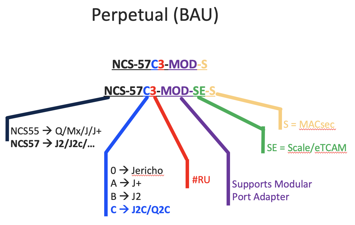
With Perpetual / Business As Usual model:
- NCS-57C3-MOD-S is the “base” version
- NCS-57C3-MOD-SE-S is the “scale” version (eTCAM)
Note that a “show platform” will display the FCM naming:
RP/0/RP0/CPU0:ios#show plat
Node              Type                       State             Config state
--------------------------------------------------------------------------------
0/0/CPU0          NCS-57C3-MODS-SYS          IOS XR RUN        NSHUT
0/0/NPU0          Slice                      UP
0/RP0/CPU0        NC57-MOD-RP2-E(Active)     IOS XR RUN        NSHUT
0/RP1/CPU0        NC57-MOD-RP2-E(Standby)    IOS XR RUN        NSHUT
0/FT0             NC57-C3-FAN2-FW            OPERATIONAL       NSHUT
0/FT1             NC57-C3-FAN2-FW            OPERATIONAL       NSHUT
0/FT2             NC57-C3-FAN1-FW            OPERATIONAL       NSHUT
0/FT3             NC57-C3-FAN1-FW            OPERATIONAL       NSHUT
0/FT4             NC57-C3-FAN1-FW            OPERATIONAL       NSHUT
0/FT5             NC57-C3-FAN1-FW            OPERATIONAL       NSHUT
0/PM0             NC57-1600W-ACFW            OPERATIONAL       NSHUT
RP/0/RP0/CPU0:ios#
Or in admin mode:
sysadmin-vm:0_RP0# show controller card-mgr inventory summary

Card Manager Inventory Summary :
                               BP                 HW
Location Card Type             ID  Serial Number  Ver    Card State
------------------------------------------------------------------------------
0/0      NCS-57C3-MODS-SYS     1   FOCxxxxxxxx    0.1    CARD_READY
0/RP0    NC57-MOD-RP2-E (Master) 27  FOCxxxxxxxx    1.0    CARD_READY
0/RP1    NC57-MOD-RP2-E (Slave) 28  FOCxxxxxxxx    1.0    CARD_READY
Product description
Positioning
NCS57C3-MOD can be positioned in a very large variety of roles in the network due to its flexibility, compact form factor and high-level forwarding capacity. Non exhaustively:
- 5G Mobile Backhaul (Class C, 1G to 400G)
- Core & Peering (MACSEC,100G, 400G, High Routing Scale)
- Enterprise & Residential Aggregation (MACSEC, 10G, 25G, 100G, Higher Aggregation Scale)
- Cloud Native Broadband Network Gateway (in roadmap)
- Routed Optical Networks (400G ZR/ZRP, PLE) (ZRP and PLE in roadmap)
CCO Documentation
The product documentation is available here:
- Datasheet:
https://www.cisco.com/c/en/us/products/collateral/routers/network-convergence-system-5500-series/ncs-57C3-fixed-chassis-ds.html- dimensions
- power usage
- PIDs
- ports
- supported standards
- pretty much everything you need to know ;)
- Fixed systems white paper:
https://www.cisco.com/c/dam/en/us/products/collateral/routers/network-convergence-system-5500-series/ncs5500-fixed-platform-architecture-white-paper.pdf - Installation guide:
https://www.cisco.com/c/en/us/td/docs/iosxr/ncs5500/hardware-install/b-ncs5700-hardware-installation-guide-fixed-port/m-ncs-5700-router-overview.html
Software
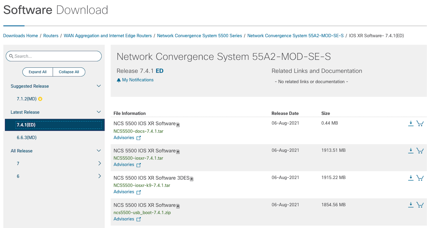
The product is launched with IOS XR 7.4.1.
Note: the system is running XR 64bit and not “XR7”. So it shares the same image than other modular and fixed chassis (except the NCS57B1 variants).
In the download center, the search engine will not help with NCS 57C3 keywords:

But you can pick any NCS5500 image to upgrade your NCS57C3-MOD routers (except the one for NCS57B1, of course since it’s XR7):
The system is based on a single J2C, the operating system will be activated by default (no config required) in “Native mode”.
From a security / integrity perspective, the NCS57C3-MOD implements the latest secureboot features with TAm (Trust Anchor module) FPGA.
Hardware
We launch two versions of this new 3-RU modular system: base and scale.
They only differ in two aspects: external TCAM to complete the J2C NPU and the number of QSFP ports.
| NCS-57C3-MOD-S / NCS-57C3-MOD-SYS | NCS-57C3-MOD-SE-S / NCS-57C3-MODS-SYS | |
|---|---|---|
| Fixed SFP 1G/10G/25G | 48 | 48 |
| Fixed QSFP 40G/100G | 8 | 4 |
| MPA bays | 2x 800G + 1x 400G | 2x 800G + 1x 400G |
| Dual RP | Yes | Yes |
| Forwarding ASIC | J2C | J2C |
| eTCAM | No | OP2 |
| Total interfaces | 4Tbps | 3.6Tbps |
| NPU Forwarding | 2.4Tbps | 2.4 Tbps |
Fixed ports (interfaces), Modular Port Adaptors (MPA) slots, Route Processors (RPs) and Power Supply Units (PSUs) are reachable from the front:
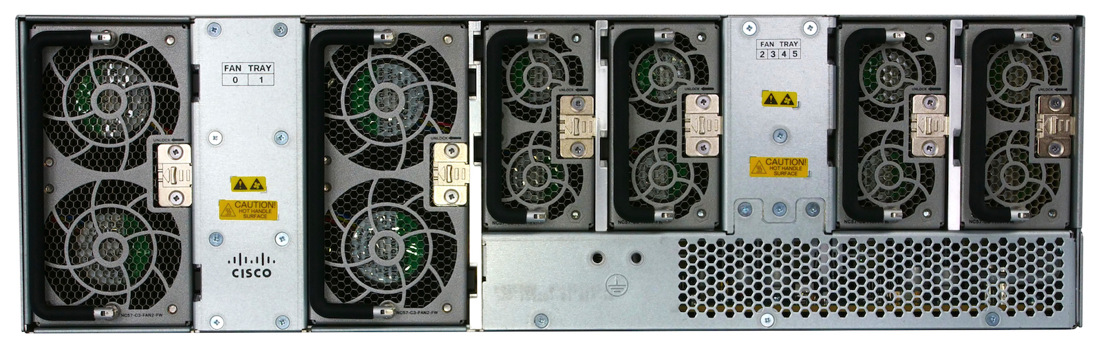
Only Fan trays are reachable from the back:
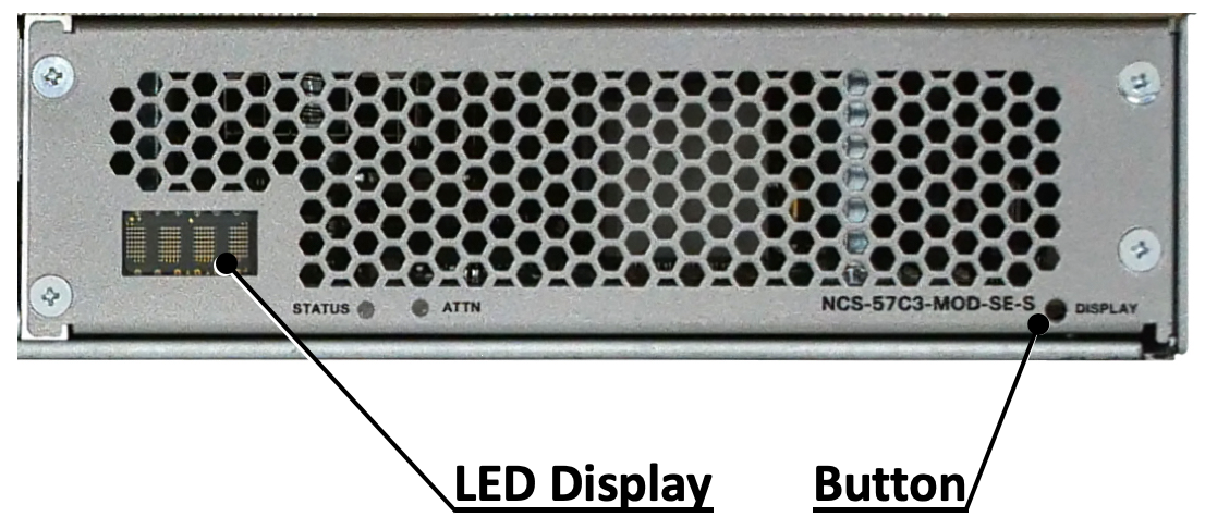
LEDs and Displays
The front plane is very packed, therefore we don’t have dedicated status LED for each port. Instead, 4 LEDs and a switch button are available on the bottom right.
Route Processors
The NCS57C3-MOD is the first of the “fixed platforms” portfolio to offer control plane redundancy via the presence of these two NC57-MOD-RP2-E inserted in the front of the router (top right two slots).
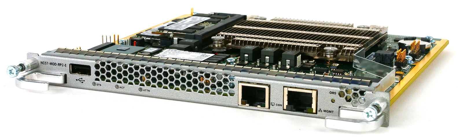
Each route processor offers an USB port (for log/dump storage or “USB boot”), a console port and an management ethernet port.
Note: the system can operate in nominal manner with only one RP. The dual RP is optional.
As mentioned above, it offers control plane redundancy and not forwarding plane redundancy. It means the protocols and processes will be checkpointed between the two route processors, in the same way it’s done on the chassis 5504/5508/5516, enabling the NSR/NSF/GR features between protocols. But at the difference of the chassis, we don’t have multiple fabric cards (no fabric card at all).
The RP doesn’t contain the Jericho2C NPU, this ASIC is located in an “internal line card”.
You’ll find details on the CPU type, memories, etc in the datasheet linked above.
Notes:
- the NC57-MOD-RP2-E is specific to the NCS57C3 and can’t be used in the modular chassis (or vice versa), it’s a totally different form factor
- we don’t have plans to implement ISSU on this system. The RP doesn’t contain the forwarding device, so at best we should be able to speed up the reload process but not reach true ISSU capabilities.
- with this dual RP architecture, the system is rated for a 5x9 availability (99.999%) at 30C.
Power supply
In the bottom left side of the front, we can insert two PSUs.
Two flavors exist: 1600W AC or 1600W DC. Both AC or DC options offer 1+1 redundancy (ie the system can operate on one module only).
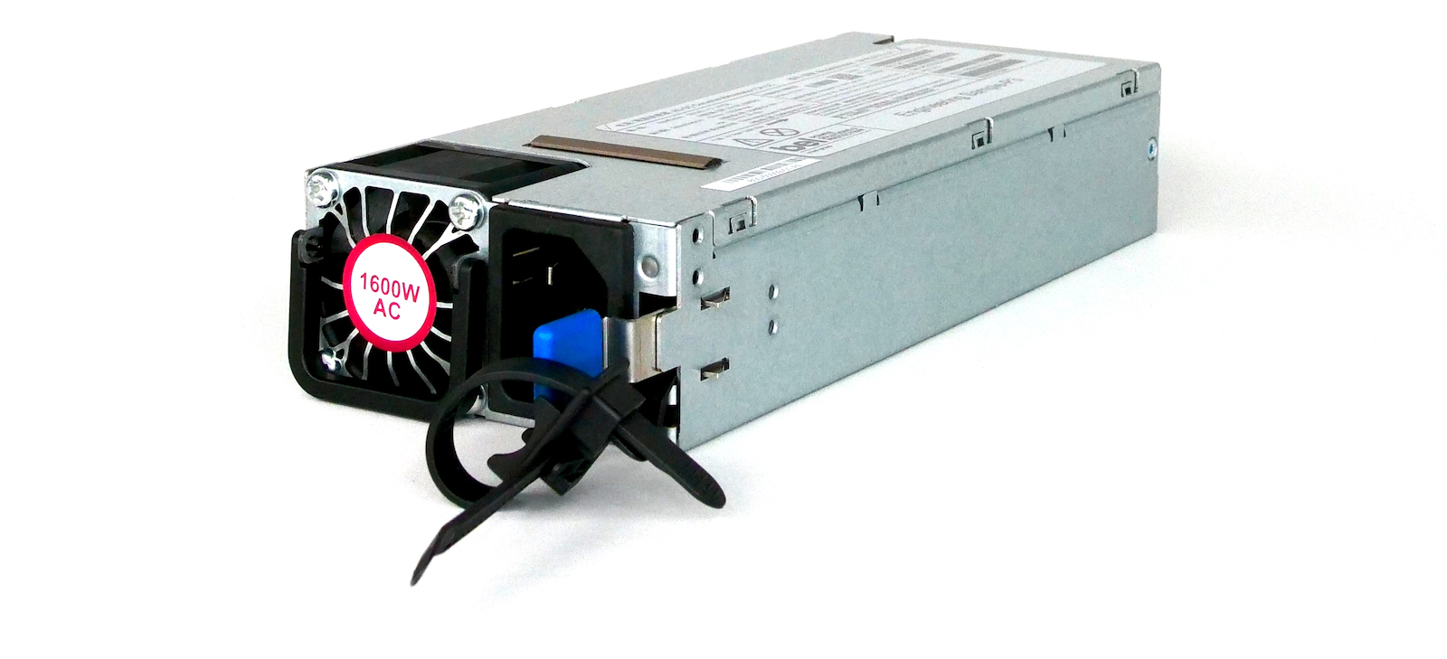
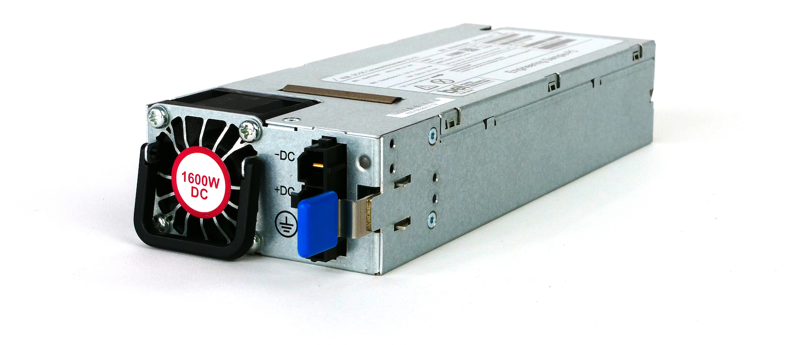
Mixed (AC+DC) is possible but only tested for short period of time (during a live migration, for example).
Fan trays
The cooling of the chassis is guaranteed by a system of 6 fan trays inserted in the back of the box. It’s a front-to-back design with two types of FTs:
NC57-C3-FAN1-FW (40mm):
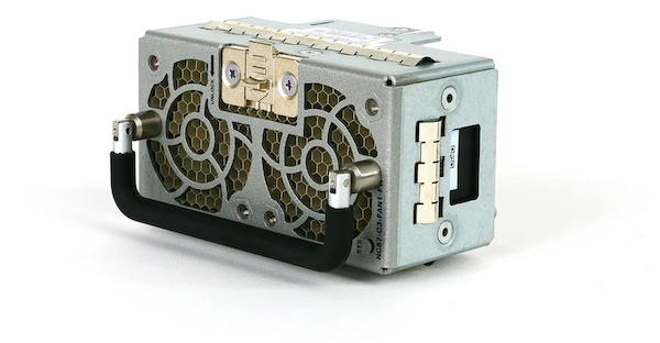
NC57-C3-FAN2-FW (60mm):
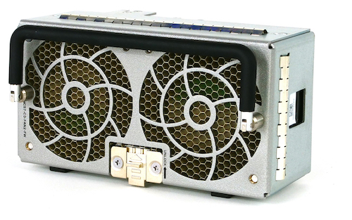
From a back perspective, the fan slots are numbered from left to right, 0 to 5.
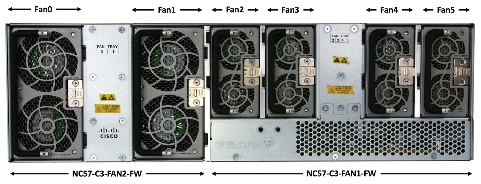
| NC57-C3-FAN1-FW | NC57-C3-FAN2-FW | |
|---|---|---|
| Size | 40mm | 60mm |
| Position/Slot | 2/3/4/5 | 0/1 |
In normal conditions (all 6 fan trays active), the system can operate at:
- 50C (at 1800m)
- 45C when using QSFP-DD MPA with low powered optics
With a single fan failure (whether it is NC57-C3-FAN1-FW or NC57-C3-FAN2-FW), the system can operate at 40C.
Ports identification
MPA ports
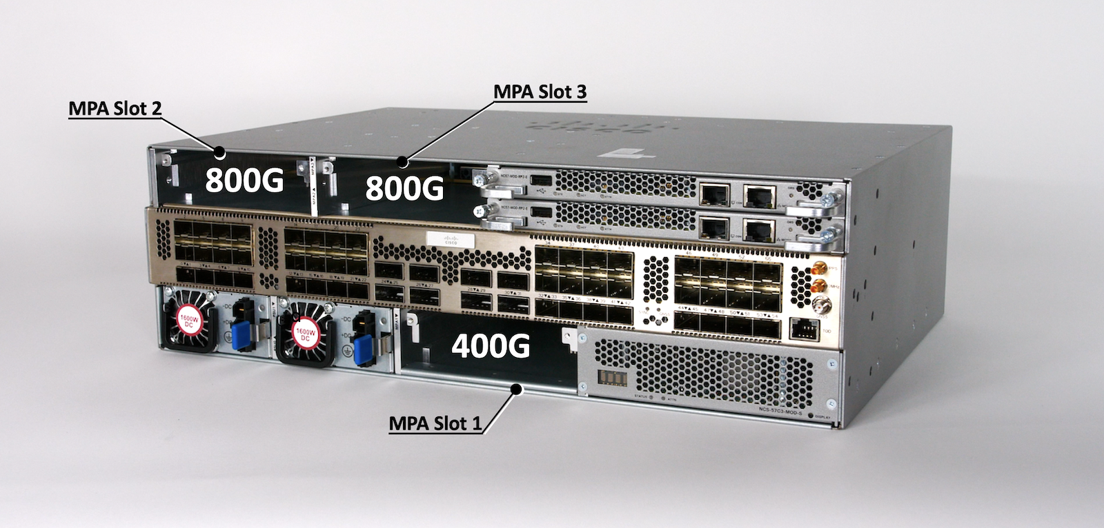
Port numbering for MPA are the same for both base and scale versions of the router. The MPA type will of course influence the port name and numbers.
NCS57C3-MOD offers three MPA bays:
- 2 for 800Gbps MPA (or 400Gbps): slot 2/3
- 1 for 400Gbps MPA only: slot 1
All slots support existing MPAs:
- NC55-MPA-2TH-S: NCS 5500 2X200G CFP2 MPA
- NC55-MPA-1TH2H-S: NCS 5500 1X200G CFP2 + 2X100G QSFP28 MPA
- NC55-MPA-12T-S: NCS 5500 12X10G MPA
- NC55-MPA-4H-S: NCS 5500 4X100G QSFP28 MPA
And slots 1 and 2 support new generation MPAs at 800G:
- NC57-MPA-2D4H-S (New): NCS 5700 4X QSFP-DD MPA
This new MPA is also supported in slot 1 in 400Gbps mode, and can’t offer 400GE connection over a single port (but 4x100GE instead).
More details on the supported ports / optics in this article: https://xrdocs.io/ncs5500/tutorials/introducing-nc57-mpa-2d4h-s/
Fixed SFP ports
NCS57C3-MOD systems are offering 1G, 10G, 25G native ports in the central raw of the system. This is actually representing an internal line card “0”. You can NOT eject this card of course. The ports will be numbered 0/0/0/x.
On base system we have 48 SFP ports split in two blocks, separated by the 8 high speed (QSFP) ports in the middle.
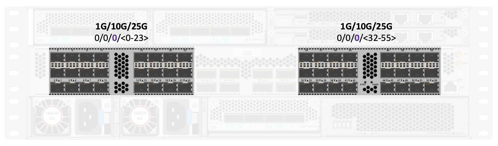
On scale system we have 48 ports split in two blocks, separated by the 4 high speed ports in the middle.
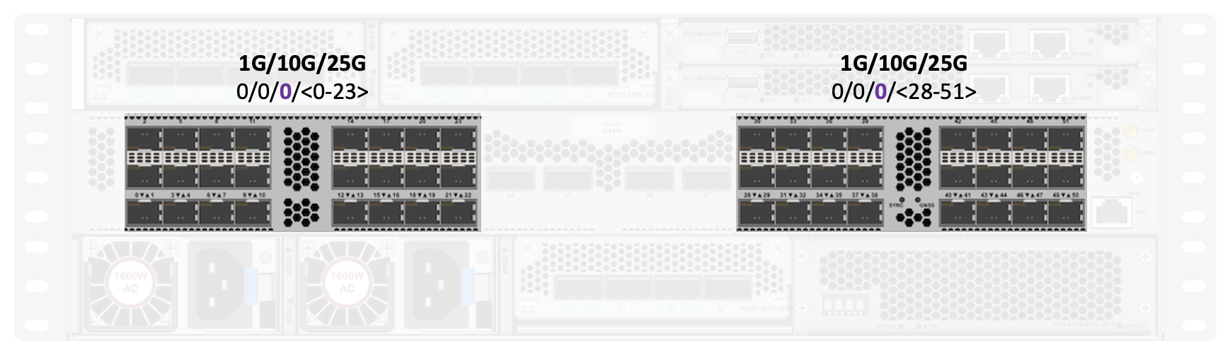
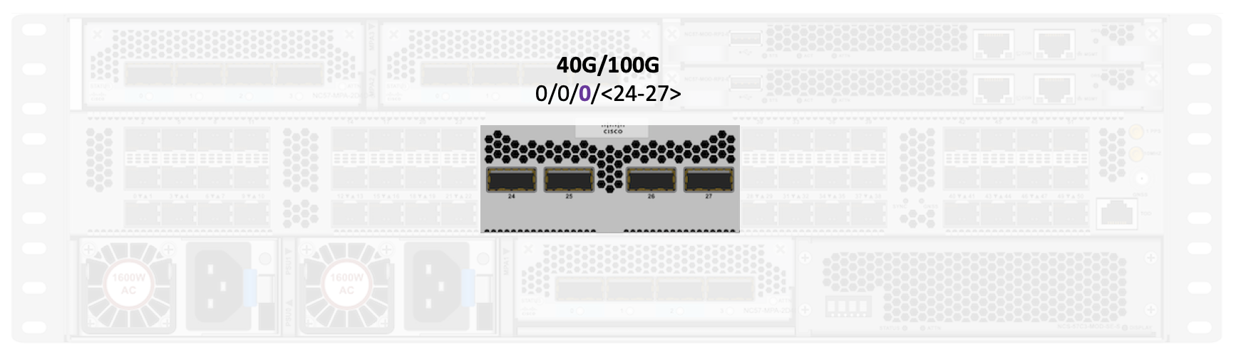
Fixed QSFP ports
That’s one of the most apparent difference between base and scale NCS57C3-MOD systems, the scale one offers half the amount of 40G/100G ports, due to the required internal connection to the external TCAM.
The base variant has 8 ports:
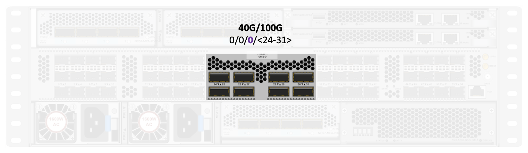
The scale variant offers 4 ports:
Ports scale and support
To identify the optic types supported on the NCS57C3-MOD routers, please check the TMG matrix:
https://tmgmatrix.cisco.com/?npid=4662&npid=4661
It contains details on the connector types, the reach, the minimum release required, etc.
1GE
The following diagram represents the maximum number of 1G optics the NCS57C3-MOD routers can offer (same numbers for base and scale system).
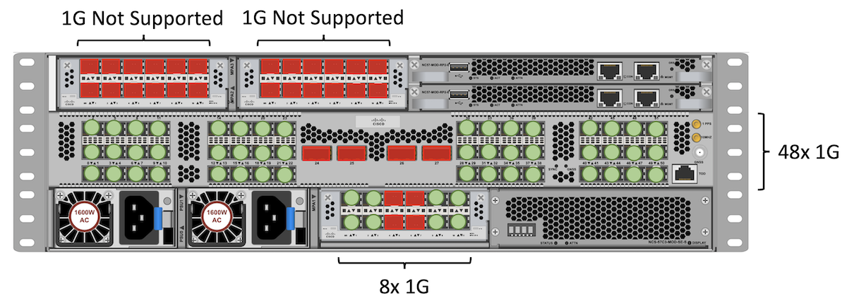
In this configuration, we are inserting NC55-MPA-12T-S in slot 1, 2 and 3 but only slot 1 (400G) can handle this MPA for 1G (it’s fine for 10G). Also, it can only support 8 ports 1GE in slot 1.
All SFP fixed ports support 1G, and at the moment, we don’t plan to support QSA in the QSFP ports.
We have a total of 48 + 8 = 56 ports 1GE.
Note: only “optical” 1G ports are supported and not “copper” (since we don’t support auto-negociation at 1G).
10GE
We repeat the same exercise to identify the max number of 10GE ports we can accomodate. We will re-use the same NC55-MPA-12T-S in all MPA slots. But this time, they will we can use all the MPA ports at 10GE.
The QSFP slots in the center can all use QSFP+ in 4x10GE breakout mode (with no restriction).
Base:
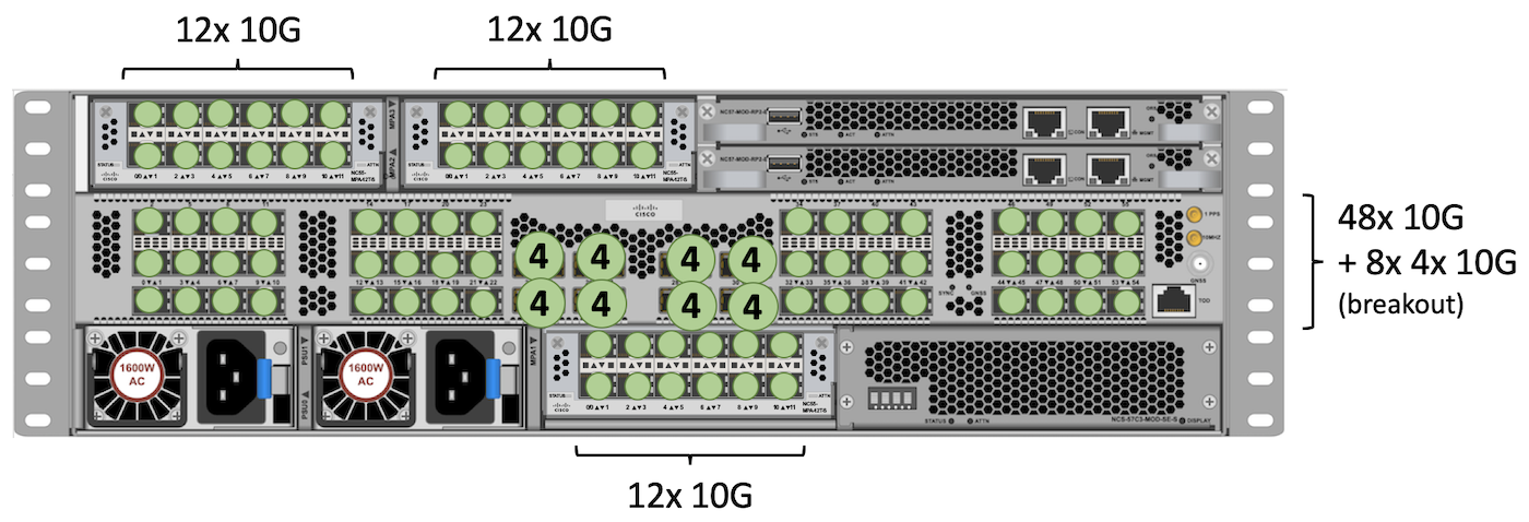
Total: 48 + (8 x 4) + 12 + 12 + 12 = 116 ports 10GE.
Scale:
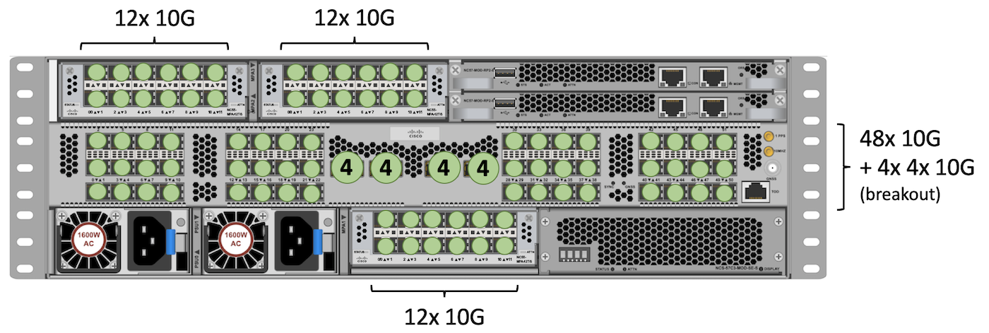
Total: 48 + (4 x 4) + 12 + 12 + 12 = 100 ports 10GE.
Note: to reach even higher 10GE scale, we could have used NC55-MPA-4H-S with QSFP+ 4x10GE in each port. With this breakout approach, we can get 12 additional ports.
25GE
To reach the higher possible scale, we will use NC55-MPA-4H-S or NC57-MPA-2D4H-S, so we can break out the four 100GE ports in 4x 25GE.
We will use the same break out option in the QSFP fixed ports in the center.
Finally all SFP fixed ports support SFP28 25GE.
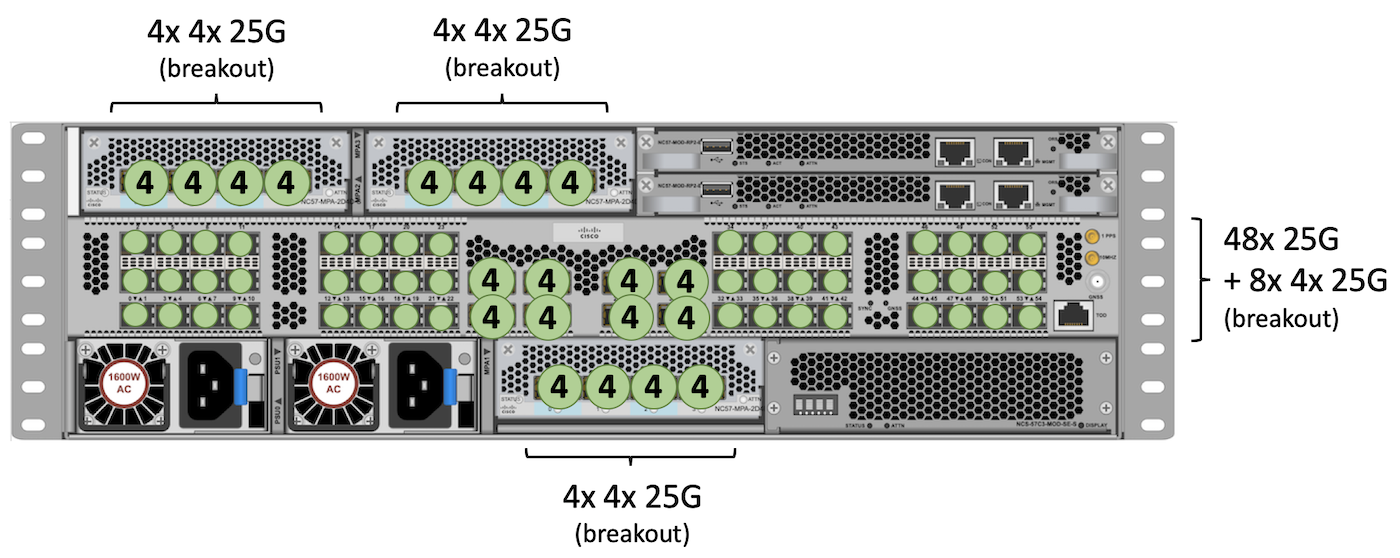
Total: 48 + (8 x 4) + 16 + 16 + 16 = 128 ports 2GE.
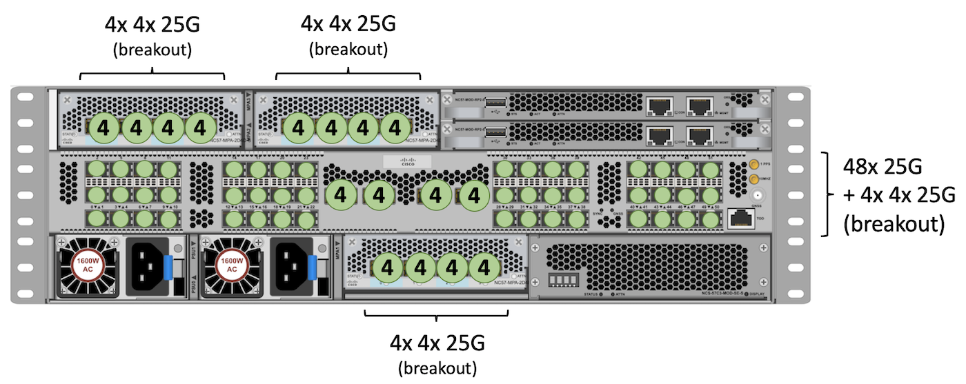
Total: 48 + (4 x 4) + 16 + 16 + 16 = 112 ports 25GE.
40GE
For QSFP+ 40GE ports, we will only be able to use the fixed QSFP ports in the center, and three times NC55-MPA-4H-S or NC57-MPA-2D4H-S.
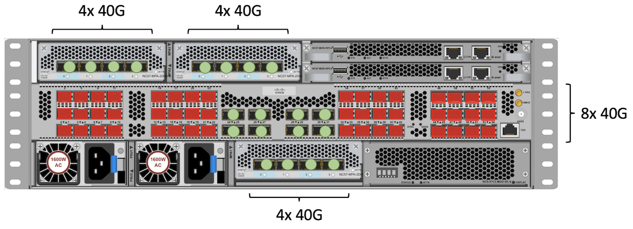
Total: 8 + 4 + 4 + 4 = 20 ports 40GE.
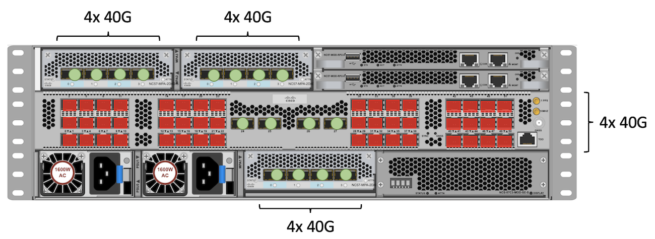
Total: 4 + 4 + 4 + 4 = 16 ports 40GE.
100GE
The highest scale we can reach for 100GE connectivity will require NC57-MPA-2D4H-S in slot 2 and 3. In slot 1, we can use NC55-MPA-4H-S or NC57-MPA-2D4H-S. We are showing two different configuration of the NC57-MPA-2D4H-S. In slot 2, we have two ports 4x100GE while in slot 3, we have 2x100 in all four ports. Both offer 8 times 100GE.
The QSFP fixed ports support natively QSFP28 optics.
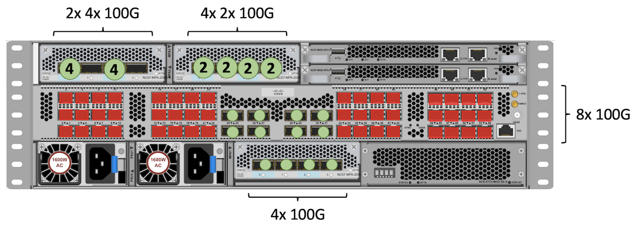
Total: 8 + (4+4) + (2+2+2+2) + 4 = 28 ports 100GE
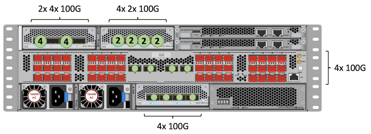
Total: 4 + (4+4) + (2+2+2+2) + 4 = 24 ports 100GE
Note: it’s also possible to use a NC57-MPA-2D4H-S in slot 1 with a 4x100G breakout, but we must use port 0 specifically in the MPA for that, other three ports will be disabled.
400GE
We only support 400GE Grey optics in NC57-MPA-2D4H-S in slot 2 and 3:
- 2 ports per MPA, in position 0 and 2
Note: this MPA in slot 1 can’t offer 400GE on a single port.
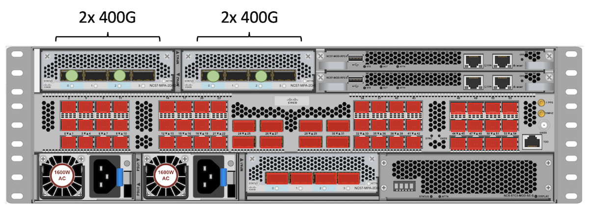
Total : 2 + 2 = 4 ports 400GE
400GE ZR
For future ZR/ZR+ use, with NC57-MPA-2D4H-S in all three MPA slots:
- in slot 2 and 3, we will support two ports in 400G Transponder mode or 4x100G Muxponder mode.
- in slot 1, we will only support one port in 4x100G Muxponder mode
The 400G-ZR/ZR+ will NOT be supported in the fixed QSFP since they require QSFP-DD cages. Same applies for the NC55-MPA-xxx.
Note: the 100G/400G ZR/ZRP are not supported in IOS XR 7.4.1, but they are in the roadmap. Contact your Cisco representative for more details.
Forwarding ASIC (J2C NPU)
NCS57C3-MOD routers are powered by a single NPU: the Broadcom Jericho2C. It’s the first platform of its kind in the Cisco MIG portfolio to use this chipset (Jericho2 being used in multiple line cards and stand-alone platforms already).
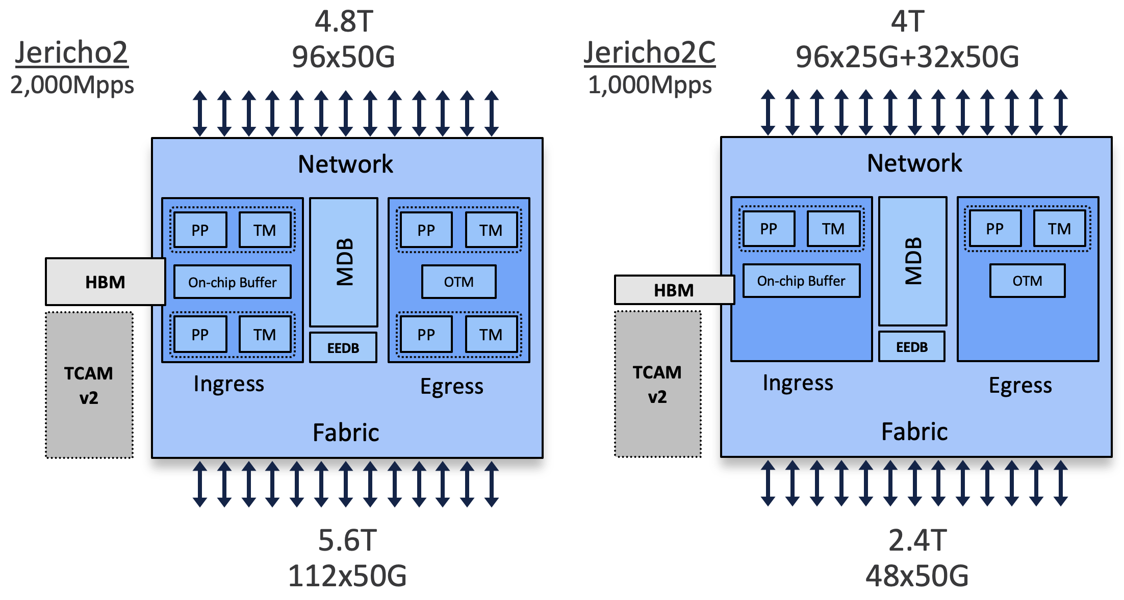
Differences with Jericho2
At very high level, the J2C ASIC is a J2 with just one core instead of two. Therefore,
- it will have half the bandwidth (2.4Tbps) and forwarding capabilities (1BPPS)
- more resources since they don’t need to be shared between two cores
| Jericho2 | Jericho2C | |
|---|---|---|
| Bandwidth (Gbps) | 4,800 | 2,400 |
| PPS | 2B | 1B |
| Network IF | 96x50G | 32x50G+96x25G |
| Fabric IF | 112x50G | 48x50G |
| On-Chip Buffer | 32MB | 16MB |
| Off-Chip Buffer (HBM) | 8GB | 4GB |
| Virtual Output Queues per Core | 64K | 128K |
| Counters | 192K | 384K |
| Timing | Class B | Class C |
MDB Profiles
The same innovations are present in the J2C and J2. Among them, the capability to carve a large block of memory into “database”, will permit the creation of specific profiles:
- more L3-oriented for peering roles
- more L2-oriented for aggregation roles
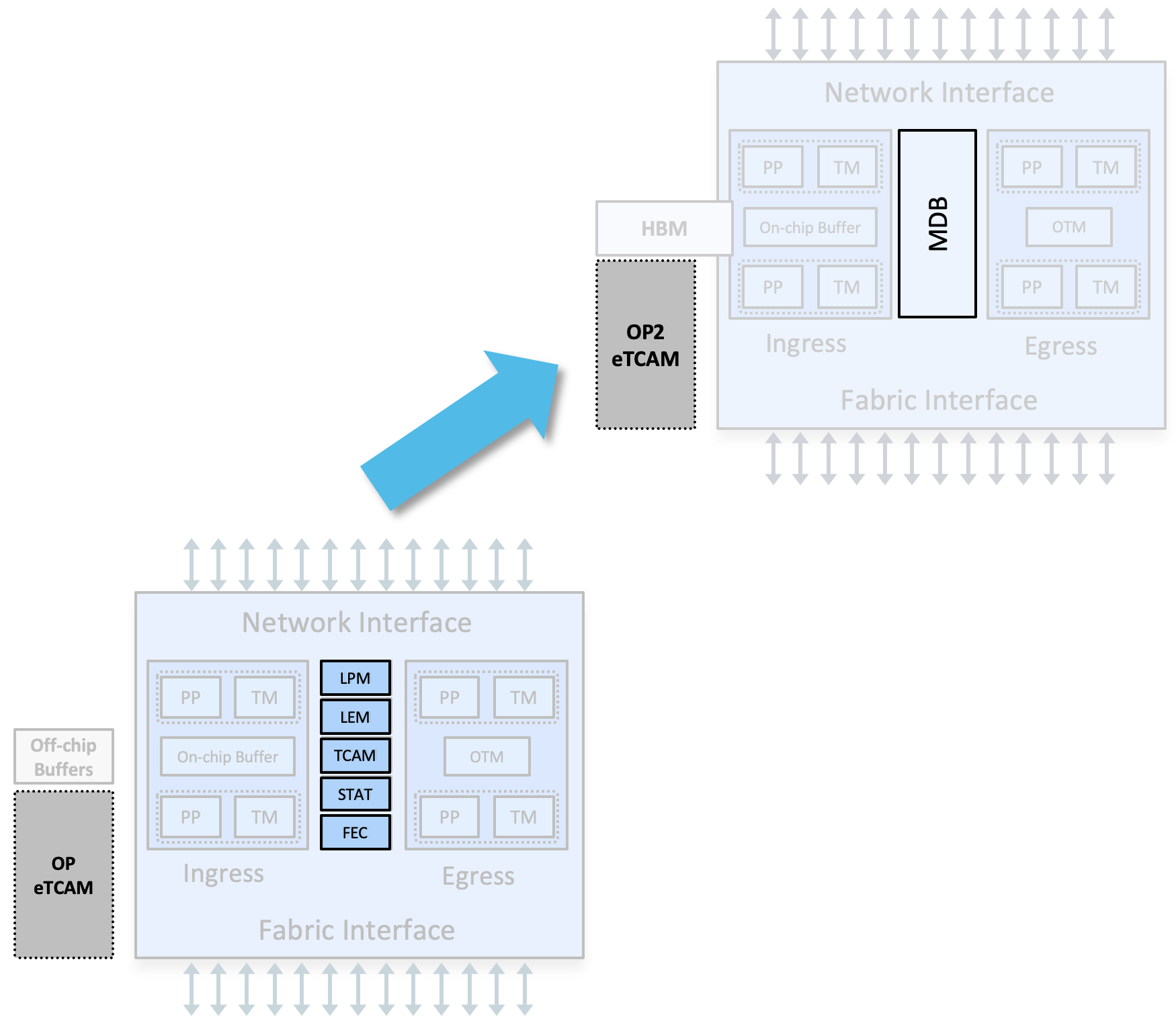
By default, in IOS XR 7.4.1, the base system will enable the L3max profile and the scale version will activate the L3max-SE profile. In future releases, we will allow the configuration of diverse profiles depending on the use-case (L2max, L2max-SE for example).
RP/0/RP0/CPU0:57C3#show controllers fia diagshell 0 "mdb info" location 0/0/CPU0

Node ID: 0/0/CPU0

R/S/I: 0/0/0
=============================
| MDB Profile               |
|   MDB profile: l3max      |
|   MDB profile KAPS cfg: 2 |
=============================
--%--SNIP-SNIP-SNIP--%--
RP/0/RP0/CPU0:57C3-SE#sh controllers fia diagshell 0 "mdb info" location 0/0/CPU0

Node ID: 0/0/CPU0

R/S/I: 0/0/0
=============================
| MDB Profile               |
|   MDB profile: l3max-se   |
|   MDB profile KAPS cfg: 9 |
=============================
--%--SNIP-SNIP-SNIP--%--
Port assignment to ASIC Core
For once, it will be very simple: it’s a single-ASIC system and it’s a single-core NPU. So all ports are connected to NPU 0 Core 0.
RP/0/RP0/CPU0:Router# sh controllers npu voq-usage interface all instance$

-------------------------------------------------------------------
Node ID: 0/0/CPU0
Intf Intf NPU NPU PP Sys VOQ Flow VOQ Port
name handle # core Port Port base base port speed
(hex) type
----------------------------------------------------------------------
Hu0/0/3/2 8 0 0 1 1 1520 6648 local 100G
Hu0/0/3/3 28 0 0 5 5 1528 6656 local 100G
Hu0/0/3/1 68 0 0 13 13 1512 6640 local 100G
Hu0/0/2/2 88 0 0 17 17 1488 6616 local 100G
Hu0/0/2/3 a8 0 0 21 21 1496 6624 local 100G
Hu0/0/2/0 c8 0 0 25 25 1472 6600 local 100G
Hu0/0/2/1 e8 0 0 29 29 1480 6608 local 100G
Te0/0/0/8 188 0 0 49 49 1088 6216 local 10G
Te0/0/0/9 190 0 0 50 50 1096 6224 local 10G
TF0/0/0/10 198 0 0 51 51 1320 6448 local 25G
TF0/0/0/11 1a0 0 0 52 52 1432 6560 local 25G
Te0/0/0/12 1a8 0 0 53 53 1104 6232 local 10G
Te0/0/0/13 1b0 0 0 54 54 1112 6240 local 10G
Te0/0/0/14 1b8 0 0 55 55 1120 6248 local 10G
Te0/0/0/15 1c0 0 0 56 56 1128 6256 local 10G
Te0/0/0/16 1c8 0 0 57 57 1136 6264 local 10G
Te0/0/0/17 1d0 0 0 58 58 1144 6272 local 10G
Te0/0/0/18 1d8 0 0 59 59 1152 6280 local 10G
Te0/0/0/19 1e0 0 0 60 60 1160 6288 local 10G
Te0/0/0/20 1e8 0 0 61 61 1168 6296 local 10G
Te0/0/0/21 1f0 0 0 62 62 1176 6304 local 10G
Te0/0/0/22 1f8 0 0 63 63 1280 6408 local 10G
Te0/0/0/23 200 0 0 64 64 1272 6400 local 10G
Hu0/0/0/24 208 0 0 65 65 1312 6440 local 100G
Hu0/0/0/25 228 0 0 69 69 1304 6432 local 100G
Hu0/0/0/26 248 0 0 73 73 1296 6424 local 100G
Hu0/0/0/27 268 0 0 77 77 1288 6416 local 100G
TF0/0/0/28 288 0 0 81 81 1424 6552 local 25G
TF0/0/0/29 290 0 0 82 82 1416 6544 local 25G
TF0/0/0/30 298 0 0 83 83 1328 6456 local 25G
TF0/0/0/31 2a0 0 0 84 84 1336 6464 local 25G
TF0/0/0/32 2a8 0 0 85 85 1344 6472 local 25G
TF0/0/0/33 2b0 0 0 86 86 1352 6480 local 25G
TF0/0/0/34 2b8 0 0 87 87 1360 6488 local 25G
TF0/0/0/35 2c0 0 0 88 88 1368 6496 local 25G
TF0/0/0/36 2c8 0 0 89 89 1376 6504 local 25G
TF0/0/0/39 2d0 0 0 90 90 1400 6528 local 25G
TF0/0/0/38 2d8 0 0 91 91 1392 6520 local 25G
TF0/0/0/37 2e0 0 0 92 92 1384 6512 local 25G
Te0/0/0/40 2e8 0 0 93 93 1264 6392 local 10G
Te0/0/0/41 2f0 0 0 94 94 1256 6384 local 10G
Te0/0/0/42 2f8 0 0 95 95 1248 6376 local 10G
Te0/0/0/43 300 0 0 96 96 1240 6368 local 10G
Te0/0/0/4 308 0 0 97 97 1056 6184 local 10G
Te0/0/0/5 310 0 0 98 98 1064 6192 local 10G
Te0/0/0/6 318 0 0 99 99 1072 6200 local 10G
Te0/0/0/7 320 0 0 100 100 1080 6208 local 10G
Te0/0/0/0 328 0 0 101 101 1024 6152 local 10G
Te0/0/0/1 330 0 0 102 102 1032 6160 local 10G
Te0/0/0/2 338 0 0 103 103 1040 6168 local 10G
Te0/0/0/3 340 0 0 104 104 1048 6176 local 10G
Hu0/0/1/0 348 0 0 105 105 1440 6568 local 100G
Hu0/0/1/1 368 0 0 109 109 1448 6576 local 100G
Hu0/0/1/2 388 0 0 113 113 1456 6584 local 100G
Hu0/0/1/3 3a8 0 0 117 117 1464 6592 local 100G
Te0/0/0/48 3c8 0 0 121 121 1200 6328 local 10G
Te0/0/0/49 3d0 0 0 122 122 1192 6320 local 10G
Te0/0/0/50 3d8 0 0 123 123 1184 6312 local 10G
TF0/0/0/51 3e0 0 0 124 124 1408 6536 local 25G
Te0/0/0/45 3e8 0 0 125 125 1224 6352 local 10G
Te0/0/0/44 3f0 0 0 126 126 1232 6360 local 10G
Te0/0/0/46 3f8 0 0 127 127 1216 6344 local 10G
Te0/0/0/47 438 0 0 135 135 1208 6336 local 10G
Te0/0/3/0/0 2048 0 0 9 9 1504 6632 local 10G
Te0/0/3/0/1 2050 0 0 10 10 1536 6664 local 10G
Te0/0/3/0/2 2058 0 0 11 11 1544 6672 local 10G
Te0/0/3/0/3 2060 0 0 12 12 1552 6680 local 10G
RP/0/RP0/CPU0:Router#
Block Diagrams
The systems are logically split in an (dual) RP part and a LC part, each powered by Intel 8-core CPUs.
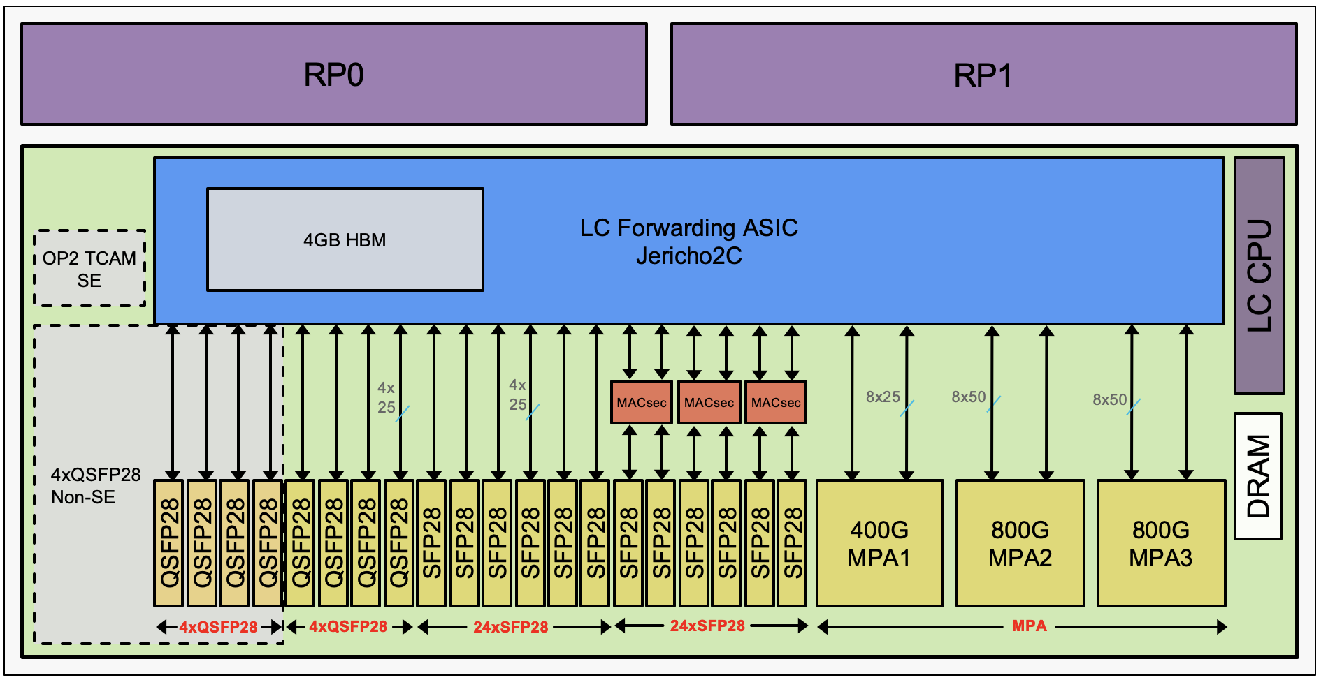
Interesting to note the NCS57C3-MOD-SYS and NCS57C3-MODS-SYS are SoC (system on the chip). That means all the ports are directly connected to a single forwarding ASIC.
But not all fixed ports are directly connected to the NPU, some SFP ports are connected through an intermediate PHY chipset.
It’s very important to identify clearly the SFP28 ports connected directly to the NPU or via this PHY, since it will impact the features you can expect to activate on them (MACsec support and Timing performance/quality).
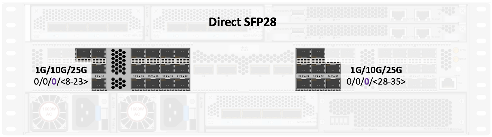
SFP28 “direct” ports
In the base version, the direct ports are 0/0/0/<8-23><32-39>
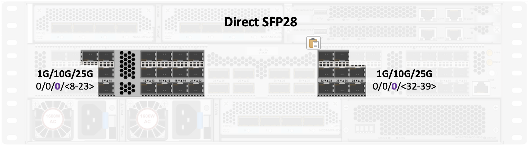
In the scale/-SE version, the direct ports are 0/0/0/<8-23><28-35>
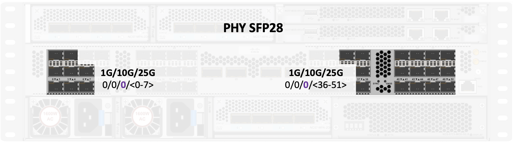
SFP28 PHY ports
In the base version, the PHY ports are 0/0/0/<0-7><40-55>
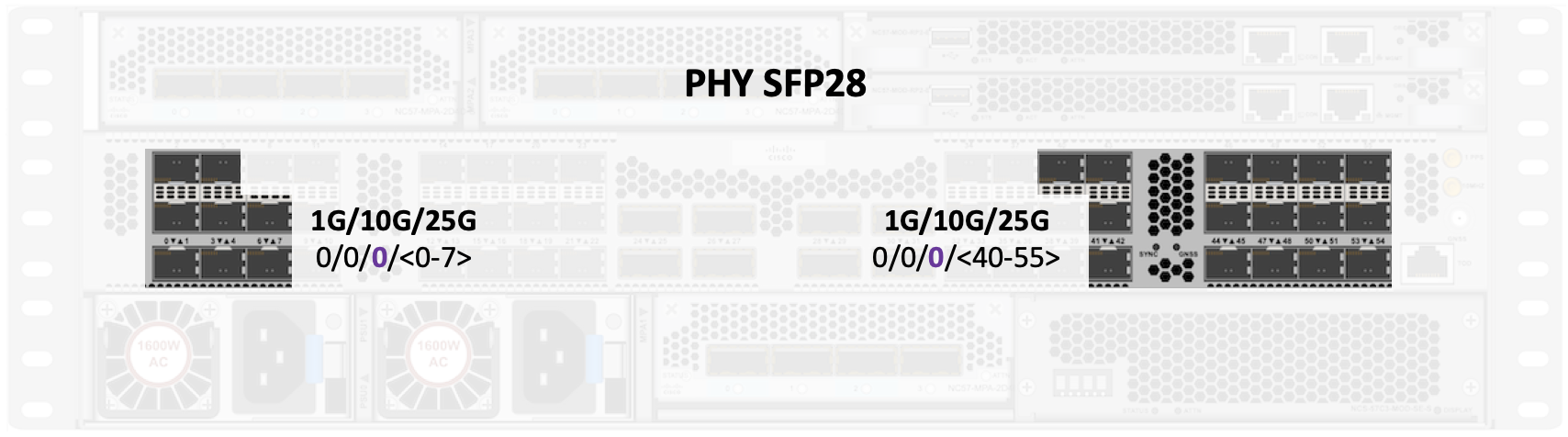
In the scale/-SE version, the PHY ports are 0/0/0/<0-7><36-51>
QSFP28 ports
All these fixed 8 or 4 ports (on base and scale respectively), are directly connected to NPU.
EOBC and EPC internal networks
Internally, the different parts of the system are interconnected through an ethernet switch that will “service” both the EPC and EOBC networks:
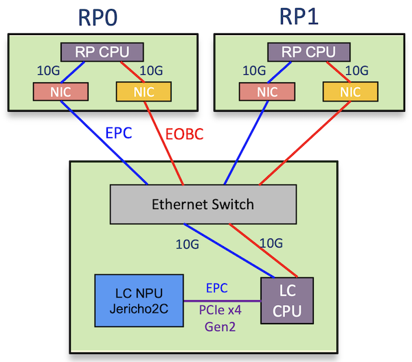
- the EPC for Ethernet Protocol Channel for the punted traffic (“for us” packets or netflow samples for example). The LC CPU and LC NPU are connected through a PCIe connection.
- the EOBC: Ethernet Out-of Band Channel for system management
MACsec
MACsec is supported on the PHY SFP28 port (check section SFP28 PHY ports above).
On fixed ports, it works for 10G and 25G optics but not 1G ports:
- base system: ports 0/0/0/<0-7> and <40-55>
- scale system: ports 0/0/0/<0-7> and <36-51>
MACsec is not supported on the direct SFP ports or the QSFP28 ports.
All MPA support MACsec, regardless of the slot of insertion
- NC55-MPA-2TH-S: supported on coherent CFP2 ports
- NC55-MPA-1TH2H-S: on both CFP2 ports and all grey ports 40G, 100G, 4x10G and 4x25G but no QSA
- NC55-MPA-12T-S: on all ports with 10G optics but not 1G
- NC55-MPA-4H-S: 40G, 100G, 4x10G and 4x25G but no QSA
- NC57-MPA-2D4H-S MACsec planned for next release and is not supported in 7.4.1.
Timing
External timing ports
In the right part of the central row of the system, you’ll find all timing ports:
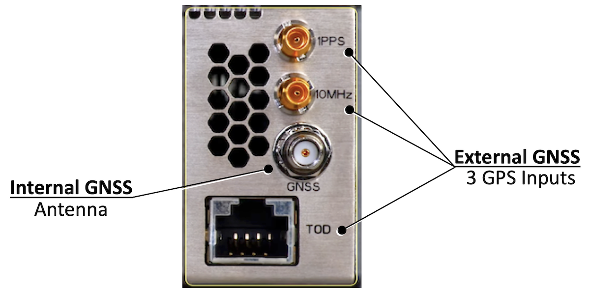
- 1PPS and 10MHz (DIN 1.0/2.3 50 Ohm Coax)
- GNSS antenna (SMA 50 Ohm Coax)
- Time Of Day (RJ45/RS-422, Cisco and NTPv4 TOD format support)
No BITS support.
Fixed ports
Cisco NCS57C3-MOD routers support Sync-E and PTP (no difference between base and scale systems).
The systems support PTP T-GM (Grand Master) clock with PRTC-A performance (G.8272).
PTP scale 128 sessions with max 64/16 pps Sync/DelayReq.
All fixed ports support Sync-E:
- QSFP ports with QSFP28 and QSFP+ optics
- SFP ports with SFP28 and SFP+ optics
- SFP ports 1G are in the roadmap and will be on PHY ports only (not supported in 7.4.1)
All fixed ports support T-BC (Boundary Clock) for both telecom profiles:
- G.8275.1/G.8273.2
- G.8275.2 (IPv4)
The clock quality (Class-B or Class-C) is dependant of the type of port, whether they are directly connected to the NPU or they are PHY ports:
- direct ports support Class-C (ports 0/0/0/<8-39> on base and ports 0/0/0/<8-35> on scale variant)
- PHY ports support Class-B (ports 0/0/0/<0-7><40-55> on base and ports 0/0/0/<0-7><36-51> on scale variant)
MPA ports
- NC55-MPA-2TH-S: Class-A timing over coherent links is in the roadmap, not supported in 7.4.1
- NC55-MPA-1TH2H-S: Class-A timing over coherent and Class-B over grey ports is in the roadmap
- NC55-MPA-12T-S: Class-B supported over 10G links in 7.4.1, but no support with 1G optics
- NC55-MPA-4H-S: Class-B is in the roadmap
- NC57-MPA-2D4H-S
- at FCS in 7.4.1, we support Class C performance on 40G/100GE and 400GE grey ports
- Timing over 2x100G and 4x100G grey breakout is in roadmap (Class C)
- Timing over ZR/ZRP, with Class A quality, is in the roadmap
Leave a Comment