Segment Routing v6 (SRv6) Transport on NCS5500/NCS500 Platforms - Part 1
| Paban Sarma, Technical Marketing Engineer ([email protected]) |
| Tejas Lad, Technical Marketing Engineer ([email protected]) |
Introduction
This is the first tutorial of the series focusing on SRv6 transport. In this document we will focus on SRv6 basics and understand how to bring up SRv6 transport on Cisco NCS 500 and NCS 5500 platforms. In the subsequent tutorials, we will cover more topics related to SRv6 transport showing implementation of layer2 and layer3 services, QoS behaviour, Traffic-Engineering etc.
Brief Background
The Service Provider transport network has evolved to provide converged transport for various 5G applications and use cases. As we already know, Segment Routing (SR) brings in programmability to the transport network using the MPLS data plane, whereas Segment Routing v6 (SRv6) uses IPv6 instead of MPLS. This offers a simpler way to build a programmable transport where we can easily do network slicing and traffic engineering for various services. This advanced series of tutorials will demonstrate new SRv6 transport on the IOS XR based NCS 5500/500 routers and explain how to configure and implement various overlay services like L3VPN/BGP-EVPN based E-Line service. In this document series, we will be using SRv6 Transport with ISIS as the IGP and provision end-to-end L3/L2 services over the transport.
Note: This document is to familiarise users with the technology. The configurations and lab setup can be taken as a reference, and this by no means represent a real production network.
SRv6 Terminology
Before starting with the topology and the configurations, let us brush up some of the important terminologies w.r.t SRv6. In this series, we will use the SRv6 uSID implementation. The SRv6 micro-segment (uSID) is an extension of the SRv6 architecture. It leverages the SRv6 Network Programming architecture to encode several SRv6 Micro-SID (uSID) instructions within a single 128-bit SID address. (In SRv6, a SID represents a 128-bit value) Such a SID address is called a uSID Carrier. For further information on SRv6 usid please visit.
| SID components | Details |
|---|---|
| Locator | This is the first part of the SID with most significant bits and represents an address of a specific SRv6 node |
| Function | This is the portion of the SID that is local to the owner node and designates a specific SRv6 function (network instruction) that is executed locally on a particular node, specified by the locator bits. |
| Args | This field is optional and represents optional arguments to the function. |
The locator part can be further divided into two parts:
| Locator Components | Details |
|---|---|
| SID Block | This field is the SRv6 network designator and is a fixed or known address space for an SRv6 domain. This is the most significant bit (MSB) portion of a locator subnet. |
| Node Id | This field is the node designator in an SRv6 network and is the least significant bit (LSB) portion of a locator subnet. |
For understanding the technology in details and the latest enhancements, please visit the following page
Reference Topology
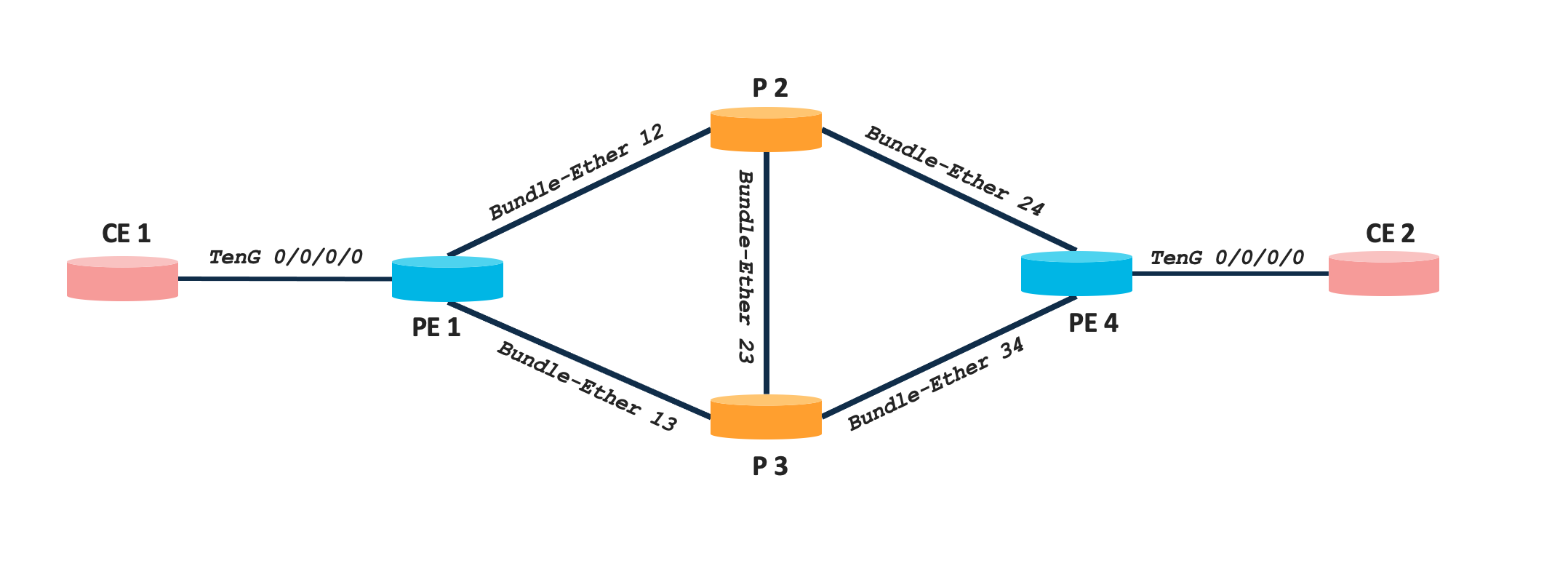
The topology used is a simple four node network comprising of Cisco NCS 540 and NCS 5500 series platforms. There are two CE nodes connected to PE1 and PE4 respectively to simulate customer networks. Details of each node along with Loopback IPs are mentioned in the below table.
| Nodes | Device Type | Software Version | Loopback0 |
|---|---|---|---|
| PE1 | NCS 540 | IOS XR 7.5.2 | fcbb:bb00:1::1/128 |
| P2 | NCS 5500 | IOS XR 7.5.2 | fcbb:bb00:2::1/128 |
| P3 | NCS 5500 | IOS XR 7.5.2 | fcbb:bb00:3::1/128 |
| PE4 | NCS 5500 | IOS XR 7.5.2 | fcbb:bb00:4::1/128 |
The loopback0 IP are choosen as per the SRv6 addressing best practice (check out segment-routing.net for more details).
Configuration Steps
To bring up SRv6 transport, the very first task to be performed is to make the underlay IGP ready. We will be using ISIS as the underlay IGP protocol to bring up IPv6 connecticity across the nodes. Once, the network is ready with IGP, there are three steps to enable SRv6, i.e.
- enabling platform hw-module profile
- configuring SRv6 locator
- enabling SRv6 over ISIS
Configuring and Verifying ISIS for reachability
ISIS is used as IGP for the sample topology. The following table summarizes the ISIS NET and member interfaces for all the nodes
| Node | net id | member interfaces |
|---|---|---|
| PE1 | 49.0000.0000.0001.00 | BE 12, BE 13 |
| P2 | 49.0000.0000.0002.00 | BE 12, BE 23, BE 24 |
| P3 | 49.0000.0000.0003.00 | BE 13, BE 23, BE 34 |
| PE4 | 49.0000.0000.0004.00 | BE 24, BE 34 |
The following snippet is for configuration on router PE1. Similarly configure the IGP ISIS on all the other routers P2, P3 and PE4 and enable all the respective interfaces.
router isis 1
 is-type level-2-only
 net 49.0000.0000.0001.00
 address-family ipv6 unicast
  metric-style wide
 !
 interface Bundle-Ether12
 point-to-point
 address-family ipv6 unicast
 !
!
 interface Bundle-Ether13
 point-to-point
 address-family ipv6 unicast
 !
!
 interface Loopback0
 address-family ipv6 unicast
 !
 !
!
Once all nodes are configured, we can verify the IPv6 routes learned via ISIS and the reachability from one node to another over ISIS.
RP/0/RP0/CPU0:LABSP-3393-PE1#sh route ipv6

Codes: C - connected, S - static, R - RIP, B - BGP, (>) - Diversion path
       D - EIGRP, EX - EIGRP external, O - OSPF, IA - OSPF inter area
       N1 - OSPF NSSA external type 1, N2 - OSPF NSSA external type 2
       E1 - OSPF external type 1, E2 - OSPF external type 2, E - EGP
       i - ISIS, L1 - IS-IS level-1, L2 - IS-IS level-2
       ia - IS-IS inter area, su - IS-IS summary null, * - candidate default
       U - per-user static route, o - ODR, L - local, G  - DAGR, l - LISP
       A - access/subscriber, a - Application route
       M - mobile route, r - RPL, t - Traffic Engineering, (!) - FRR Backup path

Gateway of last resort is not set

L    fcbb:bb00:1::1/128 is directly connected,
      10w0d, Loopback0
i L2 fcbb:bb00:2::1/128
      [115/20] via fe80::28a:96ff:fe2d:18dd, 00:01:04, Bundle-Ether12
i L2 fcbb:bb00:3::1/128
      [115/20] via fe80::28a:96ff:fe2c:58dd, 00:01:04, Bundle-Ether13
i L2 fcbb:bb00:4::1/128
      [115/30] via fe80::28a:96ff:fe2d:18dd, 00:01:04, Bundle-Ether12
      [115/30] via fe80::28a:96ff:fe2c:58dd, 00:01:04, Bundle-Ether13
C    2001:0:0:12::/64 is directly connected,
      10w0d, Bundle-Ether12
L    2001:0:0:12::1/128 is directly connected,
      10w0d, Bundle-Ether12
C    2001:0:0:13::/64 is directly connected,
      10w0d, Bundle-Ether13
L    2001:0:0:13::1/128 is directly connected,
      10w0d, Bundle-Ether13
i L2 2001:0:0:23::/64
      [115/20] via fe80::28a:96ff:fe2d:18dd, 00:01:04, Bundle-Ether12
      [115/20] via fe80::28a:96ff:fe2c:58dd, 00:01:04, Bundle-Ether13
i L2 2001:0:0:24::/64
      [115/20] via fe80::28a:96ff:fe2d:18dd, 00:01:04, Bundle-Ether12
i L2 2001:0:0:34::/64
      [115/20] via fe80::28a:96ff:fe2c:58dd, 00:01:04, Bundle-Ether13
i L2 fcbb:bb00:2::/48
      [115/11] via fe80::28a:96ff:fe2d:18dd, 00:01:04, Bundle-Ether12
i L2 fcbb:bb00:3::/48
      [115/11] via fe80::28a:96ff:fe2c:58dd, 00:01:04, Bundle-Ether13
i L2 fcbb:bb00:4::/48
      [115/21] via fe80::28a:96ff:fe2d:18dd, 00:01:04, Bundle-Ether12
      [115/21] via fe80::28a:96ff:fe2c:58dd, 00:01:04, Bundle-Ether13

RP/0/RP0/CPU0:LABSP-3393-PE1#ping fcbb:bb00:4::1 source loopback 0
Type escape sequence to abort.
Sending 5, 100-byte ICMP Echos to fcbb:bb00:4::1, timeout is 2 seconds:
!!!!!
Success rate is 100 percent (5/5), round-trip min/avg/max = 1/1/2 ms
Enabling SRv6 over IGP
Platform hw-module profile
To start with, we will configure the hw-module profile on all the routers.
RP/0/RP0/CPU0:PE1#show running-config | in hw-module
Building configuration...
hw-module profile segment-routing srv6 mode micro-segment format f3216
Note: Configure the same on all the routers.
The reason behind configuring the above hw-module profile is to explicitly enable data plane in NCS500 and NCS5500 for SRv6 with specific mode i.e. either SRv6 Base or SRv6 micro-segment (uSID). We are using uSID based SRv6 transport and this is done by configuring the hardware module profiles:“hw-module profile segment-routing srv6 mode micro-segment format f3216”. The hw-module profile is self-explanatory, we have enabled segment routing v6 (srv6) and the mode used is micro-segment. (another mode for SRv6 is the base mode). The uSID carrier format used is f3216, i.e 32 bit block size and 16bit uSID. Thus a single DA can carry upto 6 micro-instructions or uSID.
Note: This hardware-module profile configuration needs reload of the router.
Configuring SRv6 locators
As discussed above, we need to configure f3216 format locator. So for each node we will configure /48 locator of which first 32 bits will be SID block and remaining 16 bits will be Node ID.
| PE1 | P2 | P3 | PE4 |
|---|---|---|---|
| segment-routing srv6 encapsulation source-address fcbb:bb00:1::1 ! locators locator POD0 micro-segment behavior unode psp-usd prefix fcbb:bb00:1::/48 ! ! ! | segment-routing srv6 encapsulation source-address fcbb:bb00:2::1 ! locators locator POD0 micro-segment behavior unode psp-usd prefix fcbb:bb00:2::/48 ! ! ! | segment-routing srv6 encapsulation source-address fcbb:bb00:3::1 ! locators locator POD0 micro-segment behavior unode psp-usd prefix fcbb:bb00:3::/48 ! ! ! | segment-routing srv6 encapsulation source-address fcbb:bb00:4::1 ! locators locator POD0 micro-segment behavior unode psp-usd prefix fcbb:bb00:4::/48 ! ! ! |
Enabling SRv6 over ISIS
router isis 1
 address-family ipv6 unicast
  segment-routing srv6
   locator POD0
   !
  !
 !
!
Configure the above on all the routers and Thats it !!!!! You are done with the SRv6 Underlay Transport
Verification of SRv6 transport
You can use below verification commands to check the SRv6 transport.
RP/0/RP0/CPU0:PE1#show segment-routing  srv6 locator
Name                  ID       Algo  Prefix                    Status   Flags
--------------------  -------  ----  ------------------------  -------  --------
POD0                  2        0     fcbb:bb00:1::/48          Up       U
RP/0/RP0/CPU0:PE1#show segment-routing  srv6 locator POD0 detail
Name                  ID       Algo  Prefix                    Status   Flags
--------------------  -------  ----  ------------------------  -------  --------
POD0                  2        0     fcbb:bb00:1::/48          Up       U
  (U): Micro-segment (behavior: uN (PSP/USD))
  Interface:
    Name: srv6-POD0
    IFH : 0x2000800c
    IPv6 address: fcbb:bb00:1::/48
  Number of SIDs: 4
  Created: Apr 21 08:34:45.886 (1w1d ago)
RP/0/RP0/CPU0:PE1#show  isis segment-routing srv6 locators  detail

IS-IS 1 SRv6 Locators
Name                  ID       Algo  Prefix                    Status
------                ----     ----  ------                    ------
POD0                  3        0     fcbb:bb00:1::/48          Active
  SID behavior: uN (PSP/USD)
  SID value:    fcbb:bb00:1::
  Block Length: 32, Node Length: 16, Func Length: 0, Args Length: 0
RP/0/RP0/CPU0:PE1#show segment-routing srv6 sid

*** Locator: 'POD0' ***

SID                         Behavior          Context                           Owner               State  RW
--------------------------  ----------------  ------------------------------    ------------------  -----  --
fcbb:bb00:1::               uN (PSP/USD)      'default':1                       sidmgr              InUse  Y
fcbb:bb00:1:e001::          uA (PSP/USD)      [BE12, Link-Local]:0              isis-1              InUse  Y
fcbb:bb00:1:e002::          uA (PSP/USD)      [BE13, Link-Local]:0              isis-1              InUse  Y
The ipv6 route table will also be updated with the locators from the other nodes and can be verified using the routing table.
RP/0/RP0/CPU0:LABSP-3393-PE1#show  route ipv6 isis

i L2 2001:0:0:23::/64
      [115/20] via fe80::28a:96ff:fe2c:58dd, 00:10:31, Bundle-Ether13
      [115/20] via fe80::28a:96ff:fe2d:18dd, 00:10:31, Bundle-Ether12
i L2 2001:0:0:24::/64
      [115/20] via fe80::28a:96ff:fe2d:18dd, 00:11:12, Bundle-Ether12
i L2 2001:0:0:34::/64
      [115/20] via fe80::28a:96ff:fe2c:58dd, 00:10:31, Bundle-Ether13
i L2 fcbb:bb00:2::/48
      [115/11] via fe80::28a:96ff:fe2d:18dd, 00:11:12, Bundle-Ether12
i L2 fcbb:bb00:2::1/128
      [115/20] via fe80::28a:96ff:fe2d:18dd, 00:11:12, Bundle-Ether12
i L2 fcbb:bb00:3::/48
      [115/11] via fe80::28a:96ff:fe2c:58dd, 00:10:31, Bundle-Ether13
i L2 fcbb:bb00:3::1/128
      [115/20] via fe80::28a:96ff:fe2c:58dd, 00:10:31, Bundle-Ether13
i L2 fcbb:bb00:4::/48
      [115/21] via fe80::28a:96ff:fe2c:58dd, 00:10:00, Bundle-Ether13
      [115/21] via fe80::28a:96ff:fe2d:18dd, 00:10:00, Bundle-Ether12
i L2 fcbb:bb00:4::1/128
      [115/30] via fe80::28a:96ff:fe2c:58dd, 00:10:00, Bundle-Ether13
      [115/30] via fe80::28a:96ff:fe2d:18dd, 00:10:00, Bundle-Ether12
Additional Configuration Step : Enabling and Verify TI-LFA
Topology Independent Loop Free Alternate (TI-LFA) is a method of fast convergence in SR networks; the principles are identical for SR MPLS and SRv6. The backup path has to be always pre-programmed on the router which detects failure. The backup path always has to be Loop-Free. The IGP protocol has detailed knowledge about entire topology, so the IGP is always able to calculate where a packet has to be sent in case of a particular failure (without any convergence in the network). In this step we will strengthen the SRv6 transport built by enabling TI-LFA on each node. The following snippet is for the additional configuration done on PE1, the same needs to be done on each node for each IGP member link.
router isis 1
 interface Bundle-Ether12
  address-family ipv6 unicast
   fast-reroute per-prefix
   fast-reroute per-prefix ti-lfa
  !
 !
 interface Bundle-Ether13
  address-family ipv6 unicast
   fast-reroute per-prefix
   fast-reroute per-prefix ti-lfa
  !
 !
!
Now, when we verify the ipv6 routing entries, the pre-programmed backup paths will be seen. The following output shows the FRR backup paths for the respective prefix.
RP/0/RP0/CPU0:LABSP-3393-PE1#show  route ipv6

Codes: C - connected, S - static, R - RIP, B - BGP, (>) - Diversion path
       D - EIGRP, EX - EIGRP external, O - OSPF, IA - OSPF inter area
       N1 - OSPF NSSA external type 1, N2 - OSPF NSSA external type 2
       E1 - OSPF external type 1, E2 - OSPF external type 2, E - EGP
       i - ISIS, L1 - IS-IS level-1, L2 - IS-IS level-2
       ia - IS-IS inter area, su - IS-IS summary null, * - candidate default
       U - per-user static route, o - ODR, L - local, G  - DAGR, l - LISP
       A - access/subscriber, a - Application route
       M - mobile route, r - RPL, t - Traffic Engineering, (!) - FRR Backup path

Gateway of last resort is not set

i L2 fcbb:bb00:2::/48
      [115/11] via fe80::28a:96ff:fe2d:18dd, 00:15:57, Bundle-Ether12
      [115/21] via fe80::28a:96ff:fe2c:58dd, 00:15:57, Bundle-Ether13 (!)
i L2 fcbb:bb00:2::1/128
      [115/20] via fe80::28a:96ff:fe2d:18dd, 00:15:57, Bundle-Ether12
      [115/30] via fe80::28a:96ff:fe2c:58dd, 00:15:57, Bundle-Ether13 (!)
i L2 fcbb:bb00:3::/48
      [115/21] via fe80::28a:96ff:fe2d:18dd, 00:15:15, Bundle-Ether12 (!)
      [115/11] via fe80::28a:96ff:fe2c:58dd, 00:15:15, Bundle-Ether13
i L2 fcbb:bb00:3::1/128
      [115/30] via fe80::28a:96ff:fe2d:18dd, 00:15:15, Bundle-Ether12 (!)
      [115/20] via fe80::28a:96ff:fe2c:58dd, 00:15:15, Bundle-Ether13
Note: Above output is truncketed for brevity.
Summary
This concludes the Part 1 of this tutorial series. Stay tuned for the next article.
Leave a Comment