
Understanding the BFD Hardware Programming on NCS55xx and NCS5xx
Introduction
In our previous article, we discussed the BFD feature in the pipeline architecture (NCS55xx and NCS5xx). We discussed how the packet flow and the hardware resources are utilised. We saw how the scale is considered for the BFD feature and how well the resources have been carved to achieve the desired numbers. In this article, we will go a bit deeper in the BFD. We will see a sample configuration, and see how to read the BFD outputs (as per RFC 5880) and check the hardware programming.
Quick Refresh (RFC 5880)
As discussed in the previous article, the goal of Bidirectional Forwarding Detection (BFD) is to provide low-overhead, short-duration detection of failures in the path between adjacent forwarding engines, including the interfaces, data link(s), and, to the extent possible, the forwarding engines themselves. An additional goal is to provide a single mechanism that can be used for liveness detection over any media, at any protocol layer, with a wide range of Detection Times and overhead, to avoid a proliferation of different methods.
BFD Control Packet Format
Let us look at the BFD control packet format briefly. This will be useful in understanding the CLI outputs and the messages being exchanged between 2 nodes.
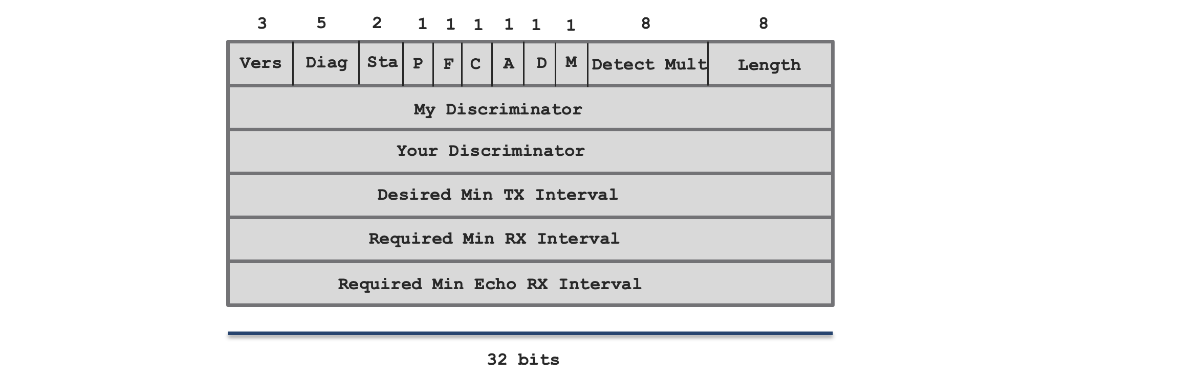
Apart from the above fields, we also have the optional Authentication section. For details please refer.
| Field | Description |
|---|---|
| Version (Vers) | The version number of the protocol. |
| Diagnostic (Diag) | A diagnostic code specifying the local system’s reason for the last change in session state. There are various values for the diagnostics which are defined in the RFC |
| State (Sta) | This indicates the current BFD session state as seen by the transmitting system. The values are: 0 – AdminDown 1 – Down 2 – Init 3 – Up |
| Poll (P) | If set, the transmitting system is requesting verification of connectivity, or of a parameter change, and is expecting a packet with the Final (F) bit in reply. If clear, the transmitting system is not requesting verification. |
| Final (F) | If set, the transmitting system is responding to a received BFD Control packet that had the Poll (P) bit set. If clear, the transmitting system is not responding to a Poll. |
| Control Plane Independent (C) | If set, BFD is implemented in the forwarding plane and can continue to function through disruptions in the control plane). If clear, BFD implementation shares fate with its control plane. |
| Authentication Present (A) | If set, the Authentication Section is present and the session is to be authenticated. |
| Demand (D) | If set, Demand mode is active. If clear, Demand mode is not active in the transmitting system. |
| Multipoint (M) | This bit is reserved for future point-to-multipoint extensions to BFD. |
| Detect Mult | Detection time multiplier. The negotiated transmit interval, multiplied by this value, provides the Detection Time for the receiving system in Asynchronous mode. |
| Length | Length of the BFD Control packet, in bytes. |
| My Discriminator | A unique, nonzero discriminator value generated by the transmitting system, used to demultiplex multiple BFD sessions between the same pair of systems. |
| Your Discriminator | The discriminator received from the corresponding remote system. This field reflects back the received value of My Discriminator, or is zero if that value is unknown. |
| Desired Min TX Interval | This is the minimum interval, in microseconds, that the local system would like to use when transmitting BFD Control packets. |
| Required Min RX Interval | This is the minimum interval, in microseconds, between received BFD Control packets that this system is capable of supporting. |
| Required Min Echo RX Interval | This is the minimum interval, in microseconds, between received BFD Echo packets that this system is capable of supporting. |
For detailed explaination of each field please refer
BFD State Machine
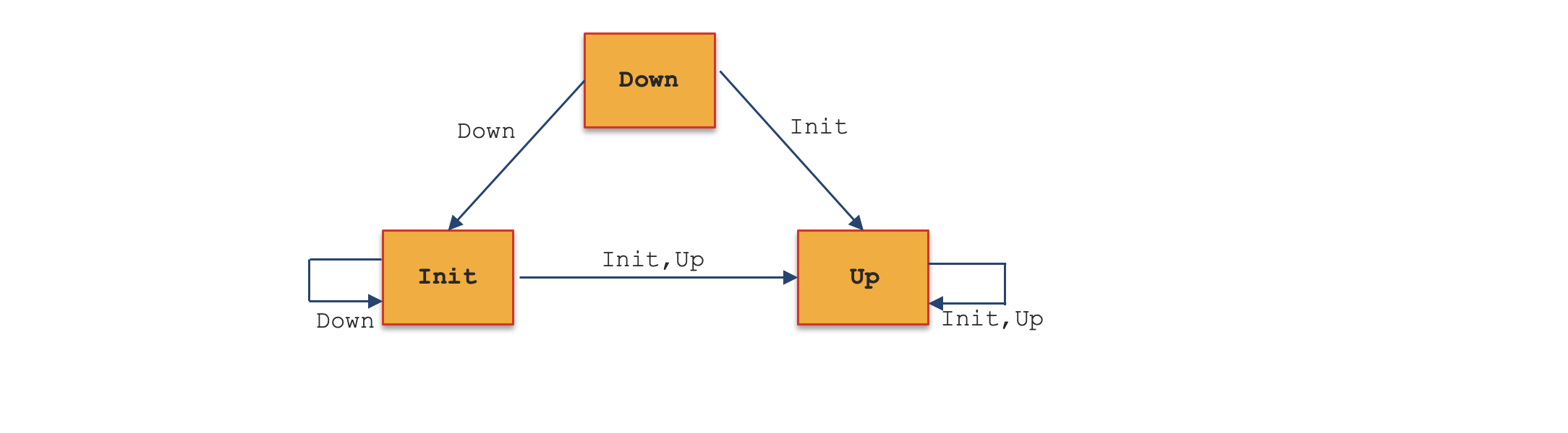
As per the RFC 5880, the BFD state machine is quite straightforward. There are three states through which a session normally proceeds: two for establishing a session : Init and Up. And one for tearing down a session: Down. This allows a three-way handshake for both session establishment and session teardown, assuring that both systems are aware of all session state changes. A fourth state AdminDown exists so that a session can be administratively put down indefinitely. Each system communicates its session state in the State (Sta) field in the BFD Control packet.
| State | Description |
|---|---|
| Down state | This state means that the session is down or has just been created. A session remains in Down state until the remote system indicates that it agrees that the session is down by sending a BFD Control packet with the State field set to anything other than Up. |
| Init state | This state means that the remote system is communicating, and the local system desires to bring the session up, but the remote system does not yet realize it. A session will remain in Init state until either a BFD Control Packet is received that is signalling Init or Up state in which case the session advances to Up state |
| Up state | This state means that the BFD session has successfully been established, and implies that connectivity between the systems is working. The session will remain in the Up state until either connectivity fails or the session is taken down administratively. |
| AdminDown state | This state means that the session is being held administratively down. This causes the remote system to enter Down state, and remain there until the local system exits AdminDown state |
Note: For details on state machine please refer the RFC
Configuring a simple BFD session (NCS55xx and NCS5xx)
After a quick refresh of the theory behind the BFD packets, let us get into the routers and check it practically. We will take a simple example and walk through the hardware programming.
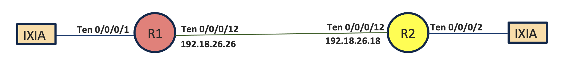
In this example, we have configured OSPF between R1 and R2 and used BFD on the physical interface. The BFD configurations are configured under the physical interface.
R1 (NCS-55A2-MOD-HD-S)
router ospf 1
 router-id 172.16.3.26
 address-family ipv4 unicast
 area 0
  !
  interface TenGigE0/0/0/12
   bfd minimum-interval 300
   bfd fast-detect
   bfd multiplier 3
   network point-to-point
  !
R2 (N540-24Z8Q2C-M)
router ospf 1
 router-id 172.16.3.18
 address-family ipv4 unicast
 area 0
  !
  interface TenGigE0/0/0/12
   bfd minimum-interval 300
   bfd fast-detect
   bfd multiplier 3
   network point-to-point
  !
Verification
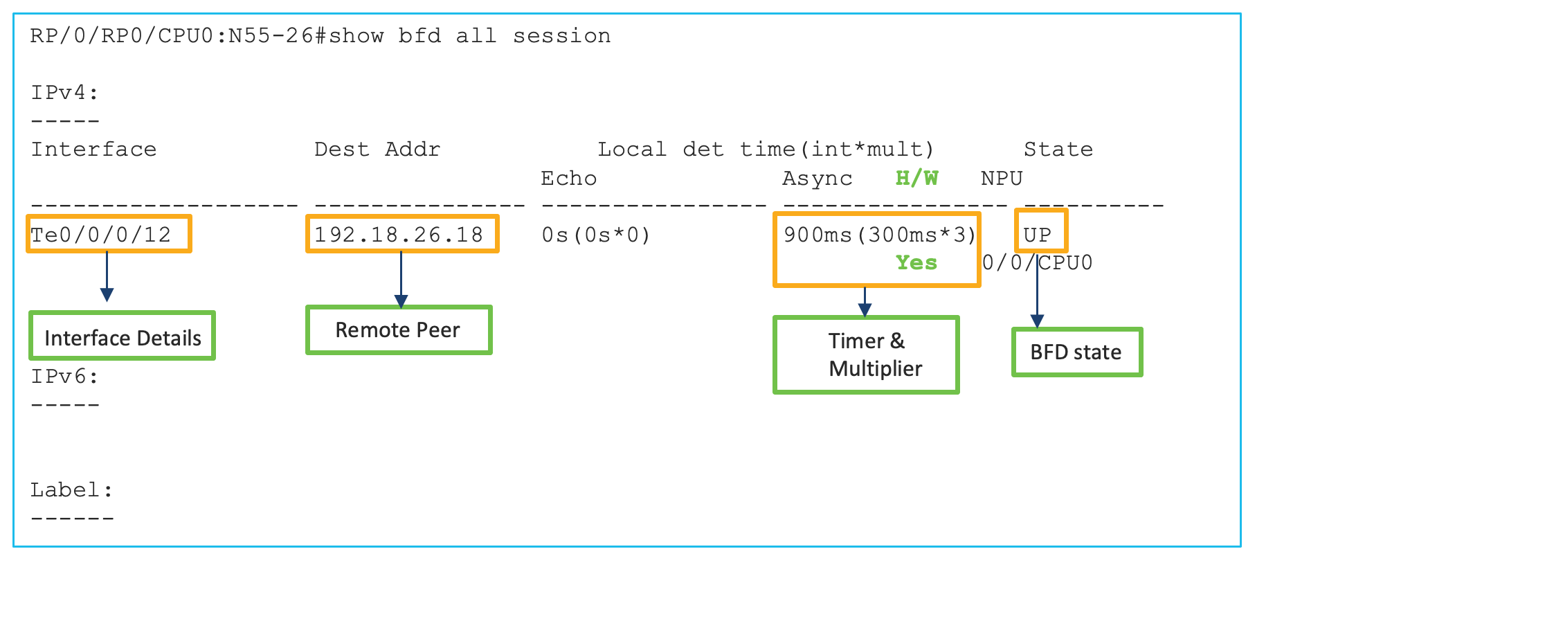
Let us verify a few CLI commands and confirm the hardware programming. This command gives a quick information of all the sessions configured.
The below command gives a detailed output of the different parameters of the BFD control packet which we mentioned in the earlier section. We can see the source and destination values, the version, state, discriminator values and different flags being set or clear. We can also see the hardware offloaded information and values. The state of the session is showing UP which indicates the programming in the hardware is done properly. If there is any programming issue, we will see the state stuck in admin down or init. Another important value to check in the output is Async Session ID and Async Tx Key. In case of hardware programming issues the value of the key would be 0.
RP/0/RP0/CPU0:N55-26#show bfd ipv4 session interface tenGigE 0/0/0/12 detail
I/f: TenGigE0/0/0/12, Location: 0/0/CPU0
Dest: 192.18.26.18
Src: 192.18.26.26
 State: UP for 0d:2h:6m:39s, number of times UP: 1
 Session type: PR/V4/SH
Received parameters:
 Version: 1, desired tx interval: 300 ms, required rx interval: 300 ms
 Required echo rx interval: 0 ms, multiplier: 3, diag: None
 My discr: 2147487749, your discr: 2147491924, state UP, D/F/P/C/A: 0/0/0/1/0
Transmitted parameters:
 Version: 1, desired tx interval: 300 ms, required rx interval: 300 ms
 Required echo rx interval: 0 ms, multiplier: 3, diag: None
 My discr: 2147491924, your discr: 2147487749, state UP, D/F/P/C/A: 0/1/0/1/0
Timer Values:
 Local negotiated async tx interval: 300 ms
 Remote negotiated async tx interval: 300 ms
 Desired echo tx interval: 0 s, local negotiated echo tx interval: 0 ms
 Echo detection time: 0 ms(0 ms*3), async detection time: 900 ms(300 ms*3)
Local Stats:
 Intervals between async packets:
   Tx: Number of intervals=3, min=7 ms, max=2184 ms, avg=829 ms
       Last packet transmitted 7598 s ago
   Rx: Number of intervals=6, min=4 ms, max=1700 ms, avg=461 ms
       Last packet received 7598 s ago
 Intervals between echo packets:
   Tx: Number of intervals=0, min=0 s, max=0 s, avg=0 s
       Last packet transmitted 0 s ago
   Rx: Number of intervals=0, min=0 s, max=0 s, avg=0 s
       Last packet received 0 s ago
 Latency of echo packets (time between tx and rx):
   Number of packets: 0, min=0 ms, max=0 ms, avg=0 ms
Session owner information:
                            Desired               Adjusted
  Client               Interval   Multiplier Interval   Multiplier
  -------------------- --------------------- ---------------------
  ospf-1               300 ms     3          300 ms     3

H/W Offload Info:
 H/W Offload capability : Y, Hosted NPU     : 0/0/CPU0
 Async Offloaded        : Y, Echo Offloaded : N
 Async rx/tx            : 292/45

Platform Info:
NPU ID: 0
Async RTC ID        : 1          Echo RTC ID        : 0
Async Feature Mask  : 0x0        Echo Feature Mask  : 0x0
Async Session ID    : 0x2054     Echo Session ID    : 0x0
Async Tx Key        : 0x80002054  Echo Tx Key        : 0x0
Async Tx Stats addr : 0x0   Echo Tx Stats addr : 0x0
Async Rx Stats addr : 0x0   Echo Rx Stats addr : 0x0
| Flags | Session Type |
|---|---|
| PR | Pre-Routed Session mostly single path sessions applicable for Physical or Sub-interfaces and BFD over Bundle interfaces |
| SW | Switched Session mostly including BFD over Logical Bundle- BLB, BFD over BVI and Multipath session |
| V4 | IPv4 Session |
| V6 | IPv6 Session |
| SH | Single Hop Session |
| MH | Multi Hop Session |
| BL | BFD over Bundle Ethernet |
| BR | BVI |
The hardware programming in the OAM engine can also be verified with the below command. The Async Session ID can be used to get the output. It clearly mentions that the BFD is processed in the OAM engine and not in the CPU. Other hardware values programmed are also matching.
RP/0/RP0/CPU0:N55-26#show controllers fia diagshell 0 "diag oam ep id=0x2054 location 0/0/CPU0
Node ID: 0/0/CPU0
=====BFD endpoint ID: 0X2054
        ***Properties:
        Type: BFD over IPV4
        BFD session is processed in OAMA (rather than CPU). TX gport: 0X6c000028
        Remote gport: 0X160040e3
        gport disabled
        Source address: 0.0.0.0 UDP source port: 49153
        Local state: up,        Remote state: up
        Local diagnostic: No Diagnostic,        Remote diagnostic: No Diagnostic
        Remote Flags: 0x8,       Local Flags 0x8
        Queing priority: 24
        BFD rate (ms): 301
        Desired local min TX interval: 300000, Required local RX interval: 300000
        Local discriminator: 2147491924, Local detection multiplier: 3
        Remote discriminator: 2147487749
        Remote detection explicit timeout: 899300
RP/0/RP0/CPU0:N55-26#
Below is another important verification which shows the history of the BFD state machine. This command gives the history of the BFD session establishment and also gives the messages being exchanged during the handshake between the neighbors. The full state machine can be checked with this command.
RP/0/RP0/CPU0:N55-26#show bfd all session status history location 0/0/CPU0
IPv4:
-----
I/f: TenGigE0/0/0/12, Location: 0/0/CPU0 table_id:0xe0000000
State: UP, flags:0x80040
Iftype: 0x1e, basecaps: 30
Async dest addr: 192.18.26.18
Async src addr: 192.18.26.26
Echo dest addr: 192.18.26.26
Echo src addr: 172.16.3.26
Additional info from Flags:
 FIB is READY
 Session Active on 0/0/CPU0
Platform Info: 0x0, Mac Length: 14
Redundancy session info:
 Created from active BFD server
Last Down Diag: Nbor signalled down
Last Rx Pkt Down Diag: Admin down
Last Down Time: May 24 15:53:17.434
Last Async Tx Counters and Timestamps:
Last Async Rx Counters and Timestamps: count 41
  [May 24 15:53:17.434]  [May 12 05:50:40.360]  [May 12 05:50:40.059]
Last Async Rx valid packets delayed or in transit:
Last Echo Tx Counters and Timestamps:
Last Echo Rx Counters and Timestamps:
Last Echo Rx valid packets delayed:
Last UP Time: May 24 15:54:23.237
Last IO EVM Scheduled Time: May 24 15:53:17.434
Last IO EVM Schedule Complete Time: May 24 15:53:16.674
Received parameters:
 Version: 1, desired tx interval: 300 ms, required rx interval: 300 ms
 Required echo rx interval: 0 ms, multiplier: 3, diag: None
 My discr: 2147487750, your discr: 2147491924, state UP, D/F/P/C/A: 0/0/0/1/0
Transmitted parameters:
 Version: 1, desired tx interval: 300 ms, required rx interval: 300 ms
 Required echo rx interval: 0 ms, multiplier: 3, diag: None
 My discr: 2147491924, your discr: 2147487750, state UP, D/F/P/C/A: 0/1/0/1/0
Tx Echo pkt :
 Version: 0, Local Discr: 2147491924, Sequence No: 0
History:
[May 24 15:54:23.237] Session (v1) state change, triggered by event 'Remote
    state up', from INIT to UP with current diag being None
[May 24 15:54:19.886] Session (v1) state change, triggered by event 'Remote
    state down', from DOWN to INIT with current diag being Nbor signalled down
[May 24 15:53:18.533] Session Down, session flags (0x80050), Echo Latency Last
    hwm 0 msrx async last hwm:3510217ms, tx async last hwm:2184ms
[May 24 15:53:17.434] Session (v1) state change, triggered by event 'Remote
    state admindown', from UP to DOWN with current diag being Nbor signalled down
[May 24 15:53:17.434] Session Down, session flags (0x80040), Echo Latency Last
    hwm 0 msrx async last hwm:3510217ms, tx async last hwm:2184ms
[May 12 05:50:39.754] Session (v1) state change, triggered by event 'Remote
    state init', from DOWN to UP with current diag being None
[May 12 05:50:39.754] Session out of Dampened State: Backoff Ctr:0, Waited:2184,
    Backoff:2000, Jitter:131
[May 12 05:50:37.570] Session (v1) state change, triggered by event 'Session
    create', from Unknown to DOWN with current diag being None
[May 12 05:50:37.570] Session in Dampened State: Backoff Ctr:0, Waited Past:0,
    Waited:0, Backoff:2000
Note: This is trimmed output
The below command gives the number of clients for the BFD
RP/0/RP0/CPU0:N55-26#show bfd client
Name                 Node       Num sessions
-------------------- ---------- --------------
L2VPN_ATOM           0/RP0/CPU0 0
MPLS-TE              0/RP0/CPU0 0
XTC                  0/RP0/CPU0 0
bgp-default          0/RP0/CPU0 0
bundlemgr_distrib    0/RP0/CPU0 0
ipv4_static          0/RP0/CPU0 0
isis-acr             0/RP0/CPU0 0
object_tracking      0/RP0/CPU0 0
ospf-1               0/RP0/CPU0 1
pim6                 0/RP0/CPU0 0
pim                  0/RP0/CPU0 0
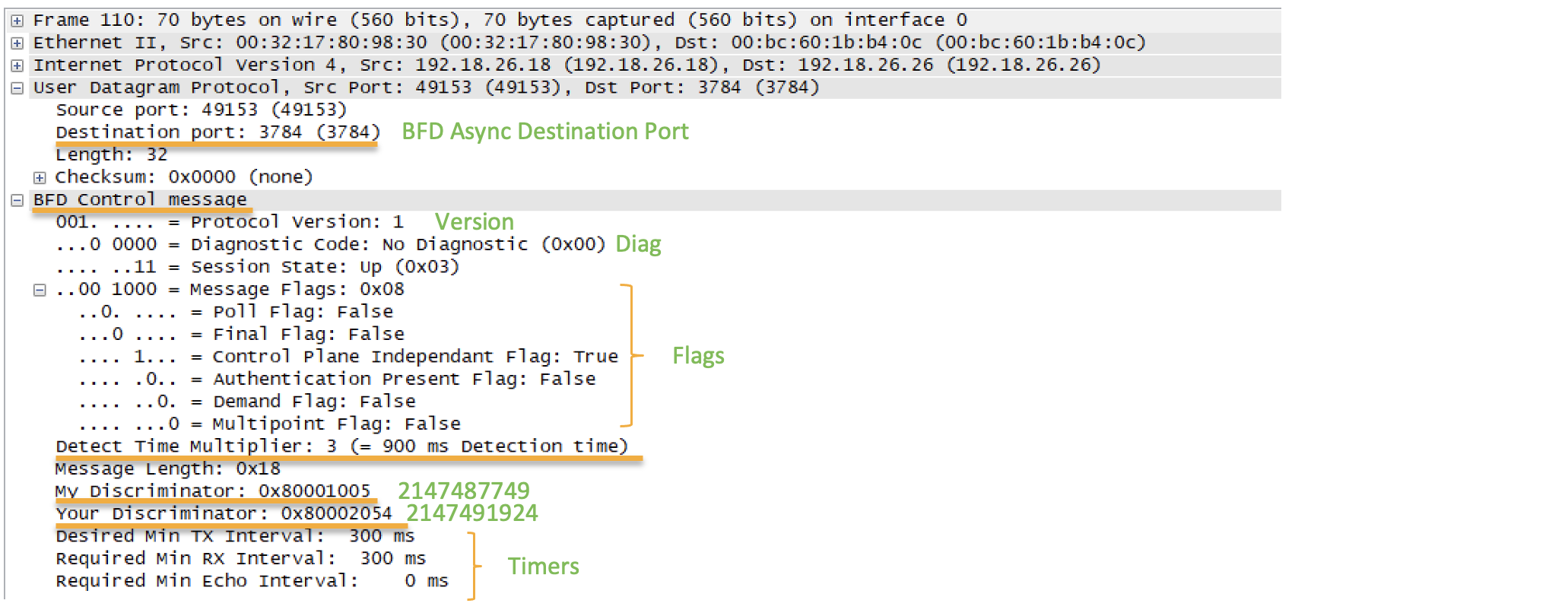
Packet Captures
Let us examine the packet capture of the control packets being exchanged between the routers. Below is the packet capture of the received parameters from the remote peer. We can verify that the values are matching with the CLI outputs we captured in the earlier commands
Timer Negotiations
Let us change the minimum timer and the multiplier value one end and see how the timer values are negotiated.
RP/0/RP0/CPU0:N540-18#show running-config router ospf 1
router ospf 1
 router-id 172.16.3.18
 address-family ipv4 unicast
 area 0
  !
  interface TenGigE0/0/0/12
   bfd minimum-interval 100
   bfd fast-detect
   bfd multiplier 3
   network point-to-point
  !
R1 has a minimum time interval value of 300ms. R2 has minimum time interval value of 100ms. What will be the negotiated timer value ? Will the session go down. Let us verify.
RP/0/RP0/CPU0:N55-26#show bfd all session
IPv4:
-----
Interface           Dest Addr           Local det time(int*mult)      State
                                    Echo             Async   H/W   NPU
------------------- --------------- ---------------- ---------------- ----------
Te0/0/0/12          192.18.26.18    0s(0s*0)         900ms(300ms*3)  UP
                                                             Yes   0/0/CPU0
RP/0/RP0/CPU0:N540-18#show bfd all session
Mon May 24 13:37:14.829 GMT+4
IPv4:
-----
Interface           Dest Addr           Local det time(int*mult)      State
                                    Echo             Async   H/W   NPU
------------------- --------------- ---------------- ---------------- ----------
Te0/0/0/12          192.18.26.26    0s(0s*0)         900ms(300ms*3)   UP
                                                             Yes   0/0/CPU0
We can see the higher timer value is negotiated
Configuring ISIS as a client for the same interface
After configuring the ISIS between the routers and configuring BFD on the interface, we can see that the BFD session will remain 1 but the clients will now show ospf and isis
RP/0/RP0/CPU0:N55-26#show bfd all session
IPv4:
-----
Interface           Dest Addr           Local det time(int*mult)      State
                                    Echo             Async   H/W   NPU
------------------- --------------- ---------------- ---------------- ----------
Te0/0/0/12          192.18.26.18    0s(0s*0)         900ms(300ms*3)   UP
                                                             Yes   0/0/CPU0
RP/0/RP0/CPU0:N55-26#show bfd all session detail
IPv4:
-----
I/f: TenGigE0/0/0/12, Location: 0/0/CPU0
Dest: 192.18.26.18
Src: 192.18.26.26
 State: UP for 0d:0h:9m:39s, number of times UP: 3
 Session type: PR/V4/SH
Received parameters:
 Version: 1, desired tx interval: 100 ms, required rx interval: 100 ms
 Required echo rx interval: 0 ms, multiplier: 3, diag: None
 My discr: 2147487751, your discr: 2147491924, state UP, D/F/P/C/A: 0/0/0/1/0
Transmitted parameters:
 Version: 1, desired tx interval: 300 ms, required rx interval: 300 ms
 Required echo rx interval: 0 ms, multiplier: 3, diag: None
 My discr: 2147491924, your discr: 2147487751, state UP, D/F/P/C/A: 0/1/0/1/0
Timer Values:
 Local negotiated async tx interval: 300 ms
 Remote negotiated async tx interval: 300 ms
 Desired echo tx interval: 0 s, local negotiated echo tx interval: 0 ms
 Echo detection time: 0 ms(0 ms*3), async detection time: 900 ms(300 ms*3)
Local Stats:
 Intervals between async packets:
   Tx: Number of intervals=3, min=304 ms, max=21 s, avg=8078 ms
       Last packet transmitted 579 s ago
   Rx: Number of intervals=5, min=2 ms, max=1832 ms, avg=683 ms
       Last packet received 578 s ago
 Intervals between echo packets:
   Tx: Number of intervals=0, min=0 s, max=0 s, avg=0 s
       Last packet transmitted 0 s ago
   Rx: Number of intervals=0, min=0 s, max=0 s, avg=0 s
       Last packet received 0 s ago
 Latency of echo packets (time between tx and rx):
   Number of packets: 0, min=0 ms, max=0 ms, avg=0 ms
Session owner information:
                            Desired               Adjusted
  Client               Interval   Multiplier Interval   Multiplier
  -------------------- --------------------- ---------------------
  ospf-1               300 ms     3          300 ms     3
  isis-1               300 ms     3          300 ms     3
H/W Offload Info:
 H/W Offload capability : Y, Hosted NPU     : 0/0/CPU0
 Async Offloaded        : Y, Echo Offloaded : N
 Async rx/tx            : 310/56
Platform Info:
NPU ID: 0
Async RTC ID        : 1          Echo RTC ID        : 0
Async Feature Mask  : 0x0        Echo Feature Mask  : 0x0
Async Session ID    : 0x2054     Echo Session ID    : 0x0
Async Tx Key        : 0x80002054  Echo Tx Key        : 0x0
Async Tx Stats addr : 0x0   Echo Tx Stats addr : 0x0
Async Rx Stats addr : 0x0   Echo Rx Stats addr : 0x0
RP/0/RP0/CPU0:N55-26#show bfd client
Mon May 24 17:32:04.194 UTC
Name                 Node       Num sessions
-------------------- ---------- --------------
L2VPN_ATOM           0/RP0/CPU0 0
MPLS-TE              0/RP0/CPU0 0
XTC                  0/RP0/CPU0 0
bgp-default          0/RP0/CPU0 0
bundlemgr_distrib    0/RP0/CPU0 0
ipv4_static          0/RP0/CPU0 0
isis-1               0/RP0/CPU0 1
isis-acr             0/RP0/CPU0 0
object_tracking      0/RP0/CPU0 0
ospf-1               0/RP0/CPU0 1
pim6                 0/RP0/CPU0 0
pim                  0/RP0/CPU0 0
So we saw a couple of examples of configuring the OSPF and ISIS as clients of BFD. The clients are not just restricted to OSPF and IS-IS. We support many other clients. For details on how to configure different clients like BGP, pim, BFD on sub interface please refer. In the netx artcile we will also cover the BFD w.r.t bundles and touch upon the concepts of BLB and BoB.
Summary
Hope this article helped you to understand the hardware programming of the BFD in the pipeline architecture. This can be used for a basic configuration and debugging before reaching out to Cisco TAC :). In the next arcticle we will try to explore the concepts of BLB/BOB/BVI and its hardware implementation.
Leave a Comment