
Y.1564 Service Activation Testing on NCS : Part1
| Paban Sarma, Technical Marketing Engineer ([email protected]) |
| Chethan K .S, Software Test Lead ([email protected]) |
Overview
The ITU-T recommendation Y.1564 defines an out-of-service test methodology to confirm the proper configuration and performance of an Ethernet service prior to customer delivery and covers the case of both a point-to-point and point-to-multipoint topology. This service activation acceptance testing of Ethernet-based services can be implemented as a test function inside of a network element. This particular functionality was introduced on Cisco NCS 500 and NCS 5500 series routers starting release IOS XR 7.1.x.
The objective of this series of articles is to capture the Y.1564 capabilities of NCS 5500 and NCS 500 series routers. We will discuss the implementation and various use-cases and their configurations & verifications. This part includes concepts, supported scenarios & configuration examples to demonstrate how operators can run Y.1564 SADT on the box.
Y.1564 Concepts:
Traffic Generation and Measurement
There are various operations as per Y.1564 viz.
- Traffic Generation Mode:
The device under test (DUT) generates the traffic and sends it out on the interface where service has been provisioned. This eliminates the need for an external probe - Passive Measurement Mode:
Here the DUT measures the traffic received on the service interface in order to verify the proper service configuration. This mode is not available in NCS 500 and NCS 5500 products. - Two way statistics collection Mode:
In this mode, traffic generation and all measurements are done locally on the DUT. Traffic is looped back on the far end after MAC swap. Based on the return traffic this mode calculates various statistics like throughput, loss etc. For this mode, the remote end needs to be properly configured to loopback the traffic sent towards it. The Y.1564 implementation on NCS 500 and NCS 5500 routers implements the two-way mode.
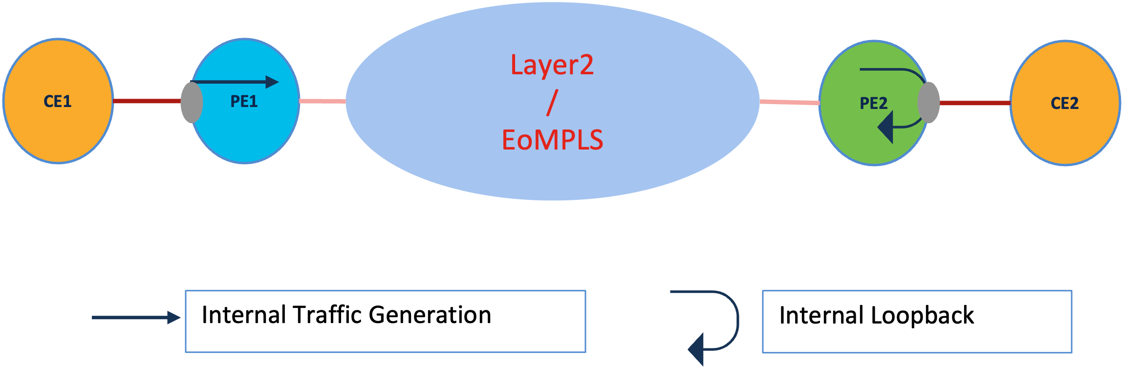
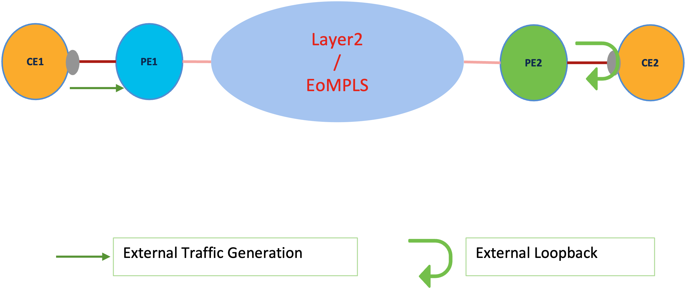
The direction of Traffic Generation can be internal or external. In internal mode the traffic is generated at the UNI and forwarded towards the network (via the service). In external mode traffic is sent out of the interface.
Target Services
The services running on the network can be both Layer2 and Layer3. The Y.1564 feature on NCS 500 and NCS 5500 routers addresses only the layer 2 point to point services, viz.
- Layer 2 local cross-connects
- Layer 2 VPWS (T-LDP PW)
- EVPN-VPWS
These L2 services can be configured on UNI based on main interface or sub-interface (both physical and bundle).
Traffic Profiles
With the current implementation of Y.1564 on NCS 500 and NCS 5500 routers can only generate layer2 traffic. The following different parameter can be specified in the Y.1564 test profile.
- Outer COS
- Inner COS
- DEI (for color aware flows)
- Packet Size
- Fixed size (range)
- EMIX pattern (defined in Y.1564)
- Destination MAC
- Information Rate (IR)
- Committed Information Rate (CIR)
- Excess Information Rate (EIR) only for color aware generation: (IR-CIR)
- Duration of the test
- 1 -1440 (minutes)
The source MAC for generated traffic flow is taken from the interface on which Y.1564 profile is attached. Destination MAC address can be specified while starting an Y.1564 test.
The following table shows the packet size for Y.1564 SADT on the NCS platforms.
| a | b | c | d | e | f | g | h | u |
|---|---|---|---|---|---|---|---|---|
| 64 | 128 | 256 | 512 | 1024 | 1280 | 1518 | MTU | user defined |
Note: 'h' in EMIX pattern refers to MTU size. In current XR releases this refers to max NPU MTU size which is 9646 bytes. Starting XR 24.2.x EMIX pattern 'h' will generate packets acoording to interface MTU size
Measurement Statistics
Y.1564 defines various parameters that can be measured on the DUT, which in turn related to the performance indicators of the service like throughput and latency. These parameters help in validating the committed SLA for the provisioned service. Cisco NCS 500 and NCS 5500 routers support the measurement of the following statistical parameters:
- Frame Loss
- Frame Loss Ratio (FLR)
- Frame Delay (FD)
- Min
- Max
- Average
Measurement of Frame Delay Variation (Jitter) is not supported. The above parameters are computed over a test duration which is configurable under the SAT profile in the range of 1 minutes to 1440 Minutes (24 Hour).
Using Y.1564 SAT
The Y.1564 testing methodology on NCS 500/5500 routers includes the following steps.
- Enable Service
- Permit Y.1564 on the interface
- Configure and Y.1564 Profile
- Run an Y.1564 test by attaching the profile to the interface
- Verifying Y.1564 Results
Enabling Service
As mentioned earlier only point-to-point L2VPN services are supported. Following config snippet shows targeted LDP based p2p VPWS configuration between two PEs
Service | Config on PE1 | Config on PE2 |
|---|---|---|
| LDP VPWS | l2vpn xconnect group vpws p2p 1001 interface TenGigE0/0/0/2.1001 neighbor ipv4 172.16.3.44 pw-id 1001 | l2vpn xconnect group vpws p2p 1001 interface TenGigE0/0/0/1.1001 neighbor ipv4 172.16.3.18 pw-id 1001 |
Permit Y.1564 on Target Interface
The service UNI or Attachment circuit needs to be enabled to run Y.1564 tests. Ideally the target interface must be an L2 transport interface (physical port or sub-interface, bundle or non-bundle). The permitted test can be either in internal or external or both depending on the type of test we want to run. Following config snippet is shown from the node PE1.(refer to logical topology in the concept section).
interface TenGigE0/0/0/2.1001 l2transport
 encapsulation dot1q 1001
 ethernet service-activation-test
  permit [internal | external | all]
Note: The Y.1564 mode by default is two-way measurement mode, so the generated traffic is expected to be looped back from remote end. This can be achieved by using Ethernet Data plane loopback feature on NCS 500 and NCS 5500 boxes. Example config to enable loopback below (from Node PE2):
interface TenGigE0/0/0/1.1000 l2transport
 	encapsulation dot1q 1000
 	ethernet loopback
  	 permit [internal | external]
Configuring Y.1564 traffic profile
This section illustrates the different components of a Y.1564 test profile. As explained in earlier section, the Y.1564 SAT profile can be color aware or color blind and various layer 2 fields can be specified. Each profile is represented by a profile name which may contain alphanumeric and special character. The mode of operation is “two-way” by default and doesn’t need configuration. Following are some examples of Y.1564 profile configuration.
Serial# | Configuration | Remarks |
|---|---|---|
1 | ethernet service-activation-test profile profile_#_1 outer-cos 5 duration 10 minutes packet-size emix information-rate 750 mbps | Color blind profile with EMIX frame size at 750 Mbps IR for duration of 10 minutes |
2 | ethernet service-activation-test profile profile_#_2 outer-cos5 duration 5 minutes packet-size 1024 information-rate 1 gbps | Color blind profile with fixed frame size of 1024 Bytes at 1Gbps IR for duration of 5 minutes |
3 | ethernet service-activation-test profile profile_#3 outer-cos4 duration 5 minutes color-aware cir 1500 mbps eir-color COS 3 packet-size 1500 information-rate 2 gbps | Color aware profile at CIR 1500 Mbps and EIR 500 Mbps. CIR COS is 4 and EIR COS is 3. DEI for EIR is not set. |
4 | ethernet service-activation-test profile profile_#4 outer-cos1 duration 5 minutes color-aware cir 700 mbps eir-color set-dei COS 0 packet-size 512 information-rate 1 gbps | Color aware profile at CIR 700 Mbps and EIR 300 Mbps. CIR COS is 1 and EIR COS is 0. DEI for EIR is set. |
5 | ethernet service-activation-test profile profile_#_5 outer-cos 5 duration 10 minutes packet-size emix sequence bchu u-value 800 information-rate 750 mbps | Color blind profile with EMIX (equal number of 128,256, MTU and 800 bytes) at 750 Mbps IR for duration of 10 minutes |
Running Y.1564 Service Activation Test
The final step is starting an Y.1564 testing. In this step the Y.1564 profile is attached to a target interface and destination MAC is configured. MAC of the target interface is used as the source MAC of generated packet. This needs to be enabled on the exec mode.
ethernet service-activation-test start interface tenGigE 0/0/0/2.1003 profile profile_#_1 destination 1.2.3 direction internal
ethernet service-activation-test start interface tenGigE 0/0/0/2.1002 profile profile_#_1 destination 1.2.3 direction external
The destination MAC adress specified is used in the generated packets. The direction can be either internal or external. The important point is that, the interface must have the service-activation-test permitted in the particular direction.
Note: Since the mode used is two way mode, the remote end must have the loopback enabled (MAC SWAP) before starting a test. Else, calculated statistics will be inaccurate.
Verifying Y.1564 Test Results
The results of an ongoing or completed Y.1564 test can be seen using the “show ethernet service-activation-test” cli. The following table summarizes the relevant list of CLIs. The test results are preserved and can be viewed until a new Y.1564 test is started on the same target interface.
List of CLIs
| CLI | DEscription |
|---|---|
| show ethernet service-activation-test | Shows details of current and past Y.1564 tests. Also includes all the interface where test is permitted but no test is run |
| show ethernet service-activation-test brief | Shows list of interface, permission and status of Y.1564 test on the target interface |
| show ethernet service-activation-test in-progress | Shows details of the currently running Y.1564 test on all target |
| show ethernet service-activation-test completed | Shows details of the past Y.1564 test on all target |
| show ethernet service-activation-test interface | Shows details of current or past Y.1564 test on the target interface specified |
Detailed Output
  RP/0/RP0/CPU0:PE1#show ethernet service-activation-test interface tenGigE 0/0/0/2.1003
Fri Dec 18 01:20:28.503 GMT+4
Interface TenGigE0/0/0/2.1003
  Service activation tests permitted
  Test completed:
    Duration 10 minute(s)
    Information rate 750 Mbps
    Color-blind
    Internal, Two-way, Destination 00:01:00:02:00:03
    Packet size EMIX, Sequence 'abceg', Pattern hex 0x00
    Outer CoS 5

  Results:
    Step 1, Information Rate 750 Mbps
      CIR packets:
        Tx packets: 94286350, bytes: 0
        Rx packets: 94286350, bytes: 38476876568

        FL: 0, FLR: 0%
        FD: Min 10.680us, Mean 12.773us, Max 18.548us
        IFDV: Not supported
        Out of order packets: 0 (0%)
        Error packets: 0 (0%)

      EIR packets:
        Tx packets: 0, bytes: 0
        Rx packets: 0, bytes: 0
        FL: 0, FLR: 0%
        FD: Min 0.000us, Mean 0.000us, Max 0.000us
        IFDV: Min 0.000us, Mean 0.000us, Max 0.000us
        Out of order packets: 0 (0%)
        Error packets: 0 (0%)
The above output can be interpreted as below:
- Test on interface Interface TenGigE0/0/0/2.1003 is completed.
- Test duration was 10 minutes.
- It was a color blind profile in two way mode in internal direction.
- Packet size is EMIX with sequence « abceg » is used, i.e equal ratio of packets sized 64,128,256,1024 and 1518 bytes are generated. The pattern is 0x00 i.e. data generated is 0x00
- Outer COS value is 5 for the generated packets.
- From the results we can see the repecteive counts of Tx and Rx packets in CIR section only as it is a color blidn profile
- The FL and FLR are 0.
- Minimum, maximum and average delay values are also shown.
- The Jitter (IFDV) is not supported as stated earlier.
- There was no error packets.
- All statistics related to EIR are shown as 0 because this is a color blind test
Conclusion:
In this article, we have captured the Y.1564 concepts and steps to implement a Y.1564 service activation test on NCS 500 and 5500 routers. In next articles we will focus on utilizing the Y.1564 functionalities like color aware generation to validate different service requirement.
Leave a Comment