
Packetizing Mobile Fronthaul with Cisco NCS540-FH
Hope you managed to spend some time on my last blog where I
- Introduced Cisco’s Converged Packet Fronthaul Portfolio
- Summarized the benefits of a packetized fronthaul solution over other (sub-optimal) optical fronthaul solutions in the industry right now
- Walked through key highlights of our Packet Fronthaul products
…and with that information, I am hoping, it will help you to justify migrating to a packet based fronthaul from the fronthaul solution currently deployed at your Radio Access Network. In this Blog, I will describe the technicalities of packetizing a traditional RAN (4G LTE), one which accounts for more than 70-80% of world’s RAN deployment.
CPRI
Back in 2003, Ericsson, Huawei, NEC, Nortel Networks and Siemens developed a proprietary internal interface of the radio base station. With the advent of Long-Term Evolution (LTE/4G), the CPRI consortium witnessed a change of guard– now, the development work on this front is being done by Ericsson, Huawei, NEC and Nokia. The latest CPRI Specification (v7.0) defines this interface as below:
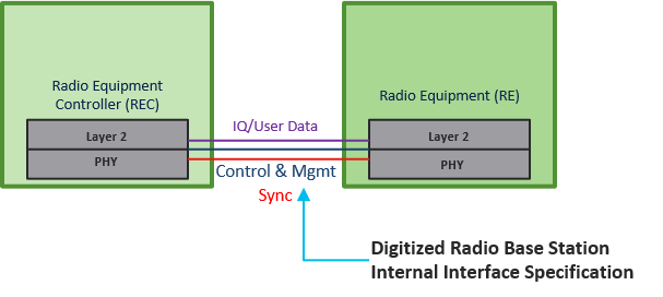
“CPRI is a digitized and serial internal base station interface between the Radio Equipment Controller (which you understand better as BaseBand Unit) and the Radio Equipment (better know to you as the Remote Radio Unit). The Interface carries User Plane Data (IQ Data), Control and Management mechanisms for transport, and means for synchronization between the RRU and BBU.”
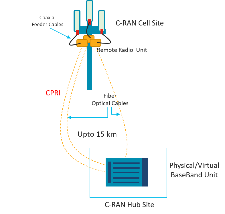
In a Cloud-RAN or Centralized-RAN deployment, the Remote Radio Unit (RRU) sits at a Cell Site (either atop the antenna or inside an Outdoor Cabinet) and far away from the Baseband Unit (BBU) which is placed at a Centralized Location (or a Far Edge Data Center as we call it now). The RRU and the BBU are connected via the CPRI Interface which carries digitized IQ (or User plane) samples back and forth to be able to deliver 4G/LTE service to the end-user. For all of you finding it difficult to connect LTE to CPRI, you should know that 1 LTE Data Frame is equal to 10 ms of a CPRI frame which are further sub-divided into Hyperframes and Basic Frames and can be interpreted in both time and frequency domain to be able to calculate relevant radio resources for a particular Cell Site or Base Station.
To understand how CPRI carries IQ or Radio resources, this is an excerpt from Anritsu.
“A CPRI link transports digitized RF signals (antenna-carriers) in a complex baseband format. Each sample has an in-phase (I) and quadrature (Q) component. The CPRI specification was specifically created to handle the signal data in this format. The I and Q samples are interleaved together to create a single word. Those words are put together in a pattern to satisfy the target sampling rate and bit width of the signal.”
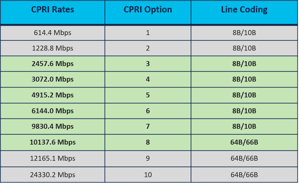
Now, let us talk a bit about the CPRI Rates and the relevant support on our NCS540-FH platform. The CPRI rates (Options) that are commonly used to carry radio resources (Antenna x Carrier) are between rates 1 and 10 as part of the Split-8 RAN Architecture (We will discuss Functional Splits in a later blog). The most used rates, though, are between 3 (2.45 Gbps) and 8 (10.1 Gbps) and can be supported using TenGigabit Interfaces. Our Converged Packet Fronthaul Portfolio - The NCS540-FH platform supports these rates (3,4,5,6,7 & 8).
Radio over Ethernet (RoE) IEEE 1914.3
We have, so far, only talked about CPRI or CPRI based constant bit rate of traffic, but in order to carry CPRI traffic over a packet based network an industry defined technique is needed to transmit all radio data types over a traditional Ethernet based Fronthaul network.
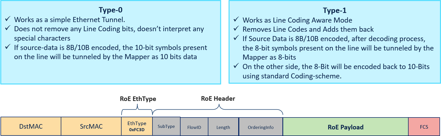
IEEE 1914.3 Radio over Ethernet is a standard specification that defines encapsulation and mapping techniques of radio protocols, for transport over Ethernet frames. While, the Structure-Agnostic mapping technique is provided for any digitized radio data, the Structure-Aware mapping is only applicable to CPRI. Our NCS540-FH platform supports both Structure-Agnostic mapping (and de-mapping) methods of CPRI based bit streams. The IEEE 1914.3 standard also fosters interoperability among implementations by defining the framing, encapsulation of the information and the common Ethernet Type (0xFC3D) for Radio over Ethernet purposes.
The details of the RoE Structure-Agnostic Mappers (Supported on the NCS540-FH) and the RoE header is shared below:
Packetizing the CPRI (A Sample Deployment)
The basic building blocks of packetizing CPRI is summarized below:
- A Control Plane consisting of the IGP (OSPF/ISIS) that will connect the Cell Site Router (CSR) and the Aggregation Router (and any P routers if applicable)
- A Data/Forwarding Plane with SR-MPLS (tightly coupled with your IGP) where we can define SR-TE policies based on constraints that a particular service requires (In case of CPRI, latency is a known constraint)
- PM/SR-PM or Segment-Routing Performance Measurement (and SR-TE) helps in determining end to end latency and populating that information into the IGP Database to be used for path selection algorithms.
- QoS or Quality of Service is required for differential treatment of radio traffic based on service level requirements of Operator. In our case, CPRI is given the highest priority
- Timing through Synchronous Ethernet and Precision Time Protocol is an essential piece of this whole solution which helps the Baseband Unit to be in sync with the Remote Radio Unit and the same clock is also used to derive any circuits between the BBU and RRU
- CPRI Rate is determined by the Antenna x Carrier (AxC) requirements at the Cell Site along with the MIMO configuration. As mentioned earlier, CPRI Rates 3 to 8 can be configured on the radio interfaces of the CSR and the Aggregation router (As the solution is bookended do note that the rates need to be the same in one CPRI/RoE flow)
- RoE or Radio over Ethernet Mapping/De-Mapping is the most important piece of this puzzle, as it will effectively packetize/de-packetize or map/de-map the CPRI traffic into an ethernet frame and back using Encapsulation techniques as specified in IEEE 1914.3. The Type-1 Mapper can save upto 20% of bandwidth as it maps 10 bits of line codes into 8 bits in the packet network.
- Finally, a Layer 2 Transport mechanism like L2VPN VPWS or EVPN VPWS will assist in carrying the RoE packets from the CSR to the Aggregation router over a SR-MPLS based packet network
Please note that, while the above sample deployment talks about SR-MPLS as the Forwarding Plane Protocol, we can even use traditional MPLS (with LDP or RSVP-TE) in place of SR-MPLS.
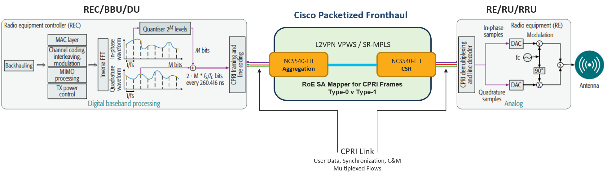
The topology below shows how our solution can be positioned between the REC and RE and is able to packetize/de-packetize CPRI bit streams
Hope this blog was informative and it has helped you to understand how NCS540-FH is packetizing and de-packetizing CPRI based radio data. In the next few blogs, I will talk to you about deploying the packet fronthaul router based on the bandwidth/resource requirements at your Cell Site.
Author : Sounak Mukherjee
Role : Technical Marketing Engineer | 5G | Mobile Fronthaul
Leave a Comment