
Internet Edge Peering - Current Practice
Introduction
The Internet was created to provide transparent data services across interconnected packet switched networks. The interconnection and exchange of Internet routing data between two networks is known as Peering. Peering is the glue holding together the Internet, without it the flow of data across the Internet would not be possible. Peering represents an important administrative, operational, and security boundary between networks. Peering is a subject of great interest in many areas, from analytics to politics. This paper will focus on the technical aspects of peering covering peering history and current peering architecture in the areas of network, security, and telemetry.
Peering Background
Peering History
The Internet became ubiquitous across the globe in the early 1990s largely due to the construction of Internet connection points known as IXPs or Internet Exchange Points. The IXP provided a place for networks to connect and exchange traffic. The initial IXPs constructed were slightly different than the exchange points of today, but by the middle of the 1990s they began to look markedly similar to today’s IXPs. The initial four major North American IXPs, known as NAPs or Network Access Points were operated by traditional telephone companies. As the Internet grew the steep rise in traffic necessitated the creation of more IXPs and private enterprises created a number of carrier-neutral IXPs across the globe. These facilities also provide physical cross-connect services to allow networks to peer directly with each other, bypassing the IXP fabric. Hundreds of IXPs exist today across the world, along with thousands of private interconnections between organizations.
IXP Fabric vs. Private Network Interconnect
The easiest way to interconnect the large number of networks joining the Internet was for the IXP itself to create a peering “fabric” facilitating connectivity from one network to many other networks via a single physical connection to each member network. Multiplexing technology such as ATM VCs were used initially, replaced with Ethernet VLANs or flat Ethernet broadcast domains as Ethernet became the dominant medium.
In the earlier days of the Internet, producers and consumers were more widely distributed as regional residential and business providers provided services to both along with major telephony carriers. As broadband connectivity has become ubiquitous across the world, service and content providers have evolved to meet user’s needs. In North America for example, Internet connectivity to residential consumers has been consolidated to a small number of providers. There are also relatively few mobile providers, an area seeing tremendous traffic growth. In addition, the content being consumed is produced by a much smaller number of content providers, most of whom have created their own peering presence. This has led the “eyeball” consumer networks to peer directly with content provider networks over PNI (Private Network Interconnection) instead of utilizing IXP fabrics. The reduction in pricing of Internet transit has also lead to more use of transit for low bandwidth peers, also negating the need for IXP fabric connections.
Outside North America broadband consolidation has not occurred at the same rate and the decoupling of physical infrastructure from network service has led to many more network providers who interconnect with each other and content providers. IXP fabrics are still widely used across the world today in regional IXPs and large IXPs outside North America. In North America peering fabrics have largely been replaced by the use of Private Network Interconnection.
Localized Peering
While the bulk of Internet peering still occurs in a relatively small number of IXPs in the US, there has been an effort in the last several years to interconnect closer to consumers. The main driver is the cost to carry traffic across long-haul networks from the traditional peering locations to the consumers they serve in larger markets across a large geographic distance. Building and maintaining equipment in a more distributed peering fabric has become more feasible vs increasing capacity on long-haul fiber networks. In addition, it improves the quality of experience for end users since content is served closer to the consumer.
B2B IP Peering
An often-overlooked form of peering is B2B peering between different networks. There are many examples of B2B peering, the most visible today are those connecting datacenter colocation providers to cloud service providers. Additionally, B2B peering is used for linear video content providers to send video to end providers, carry voice services over IP instead of PSTN, and interconnect various service owners to consumers.
Peering Hardware
The main requirements when looking at peering network hardware are
Physical, power, and cooling footprint
10G/100G interface density
Software support for necessary peering features
The Cisco Visual Networking Index has shown a 1270% rise in Internet traffic over the last 12 years and projects a threefold increase over the next five years. Peering routers require flexible high-density hardware supporting the required software feature sets needed for Internet peering. The Cisco NCS 5500 platform powered by IOS-XR satisfies today’s peering needs along with capacity for future traffic growth. Most peering locations are third party facilities where space and power can add considerable cost. Across the entire NCS 5500 series density is greater than 24x100GE per RU, with the NCS 5504, 5508, and 5516 chassis systems providing 36x100GE per RU, all at power consumption of approximately .3/Gbps. In addition to high density 100GE, every NCS 5500 QSFP+ port supports 4x10GE breakout options to connect to 10GE peers as well as downstream caching devices in the case of content provider edge peering.
More information on the Network Convergence System 5500 series can be found at http://www.cisco.com/c/en/us/products/routers/network-convergence-system-5500-series/index.html
Peering Network Design
Traditional SP IXP Network Design
Traditional SP peering is distributed to one or more geographic locations driven by the convenience of having peers in the same IXP location. There is a need to maintain those locations today as not everyone has the capability of interconnecting everywhere. Peering center network design has typically been done with two or more larger edge peering routers with either direct connections to an optical backbone or connections to another stage of backbone routers as seen in left hand side of Figure 1. In recent years, there has been a trend to more modular network design within the peering center using smaller fixed or chassis systems, allowing the use of best of breed hardware and flexibility to add capacity more granularly. The topology mimics the folded CLOS networks, scaling horizontally across peer connections and minimizing impact during failures. Also, datacenter space in traditional IXP facilities has become more limited in recent years, leading the carrier neutral facility providers to expand to multiple facilities within a metropolitan area. Placing smaller high-density systems to multiplex peer connections onto higher speed links is more cost effective than paying the MRC of inter-facility cross-connects per peer connection.
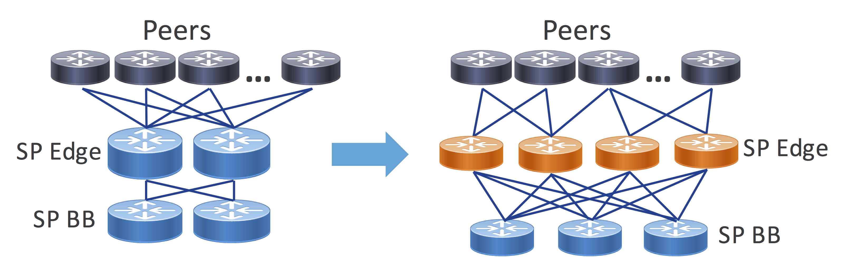
Figure 1 - IXP Network Design Evolution
Distributed SP Peering Fabric
While traditional IXP facilities are still important, reducing the distance and network hops between where packets enter your network and exit to the consumer is a high priority for service providers. Each pass through an optical transponder or router interface adds additional cost to the transit path. The rise in video traffic over the next several years demands Internet peering at the edges of the network to serve wireline broadband subscribers along with high-bandwidth 5G mobile users. Content providers have invested heavily in their own networks as well as distributed caches serving content from any network location with Internet access. Third party colocation providers have begun building more regional locations supporting PNI between content distributors and the end subscribers on the SP network. This leads to a localized peering option for SPs and content providers, greatly reducing the distance and hops across the network. The right-hand diagram of Figure 1 is an example of how more distributed peering is changing the landscape of peering.
An initial step may be to create a single localized peering facility within a region but as traffic demands increase or more resiliency is needed it can drive the addition of multiple facilities within a region.
Reduced footprint high capacity routers are ideal for serving the needs of a distributed peering network. The NCS 5501, 5502, and 5504 are ideal, providing high density peer termination in a compact, efficient package while not sacrificing features or protocol scale.
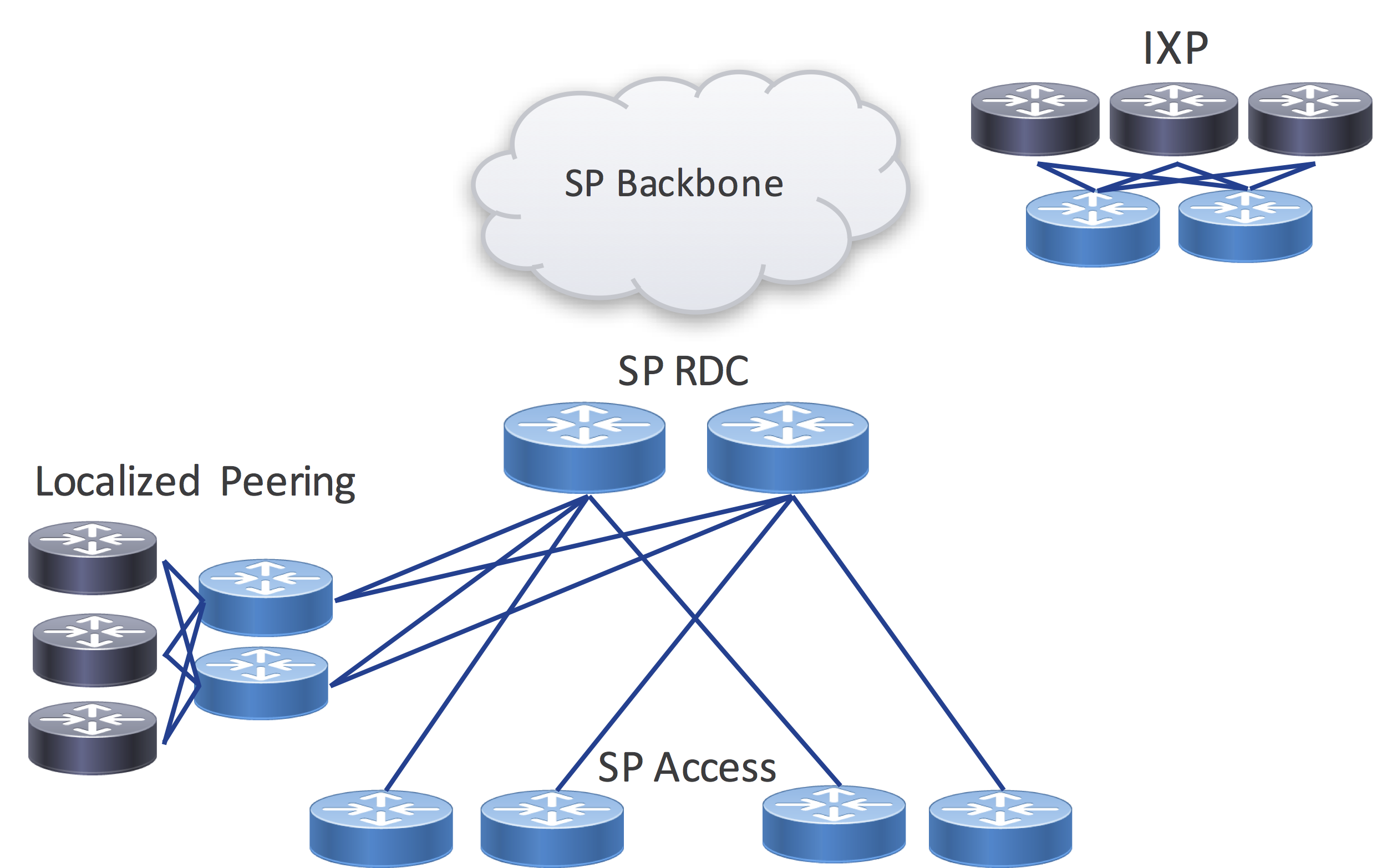
Figure 2 - Localized Peering
Regional Core Bypass / Express Peering
Regional SP networks serving residential subscribers are typically deployed in an aggregation/access hierarchy using logical Ethernet connections over a metro optical transport network. The aggregation nodes serve as an aggregation point for connections to regional sites along with acting as the ingress point for traffic coming from the SP backbone. If a distributed peering fabric is implemented, SPs can drive even greater efficiency by selecting specific high bandwidth regional sites for core bypass. This is simply connecting the regional hub routers directly to a localized peering facility, bypassing the regional core aggregation nodes which are simply acting as a pass through for the traffic. Due to the growth in Internet video traffic, this secondary express peering network in time will likely be higher capacity than the original SP converged network. The same express peering network can also be used to serve content originated by the SP, leaving the converged regional network to serve other higher priority traffic needs.
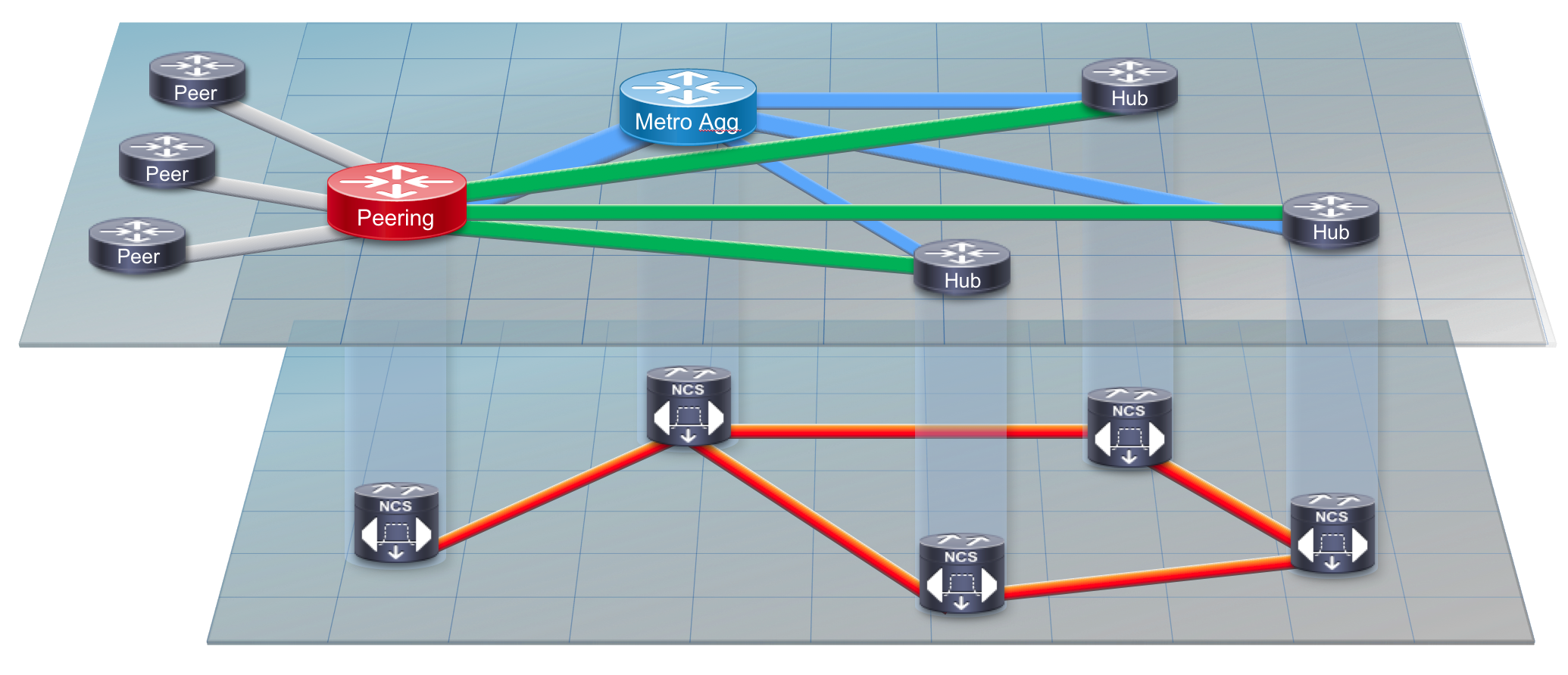
Figure 3 - Express Peering Fabric
Peering Network Resiliency
Peering resiliency refers to the ability for the network to cope with the loss of a peer, peering router, or peering facility. Apart from B2B peering instances, almost all traffic coming over a peering link is considered best-effort low priority traffic. Even though most traffic is BE, it is recommended for SPs to dual-home to high bandwidth sources of inbound traffic within the same facility or region. Since most larger SPs peer with the same providers in diverse geographic locations, it is more cost-effective to maintain multiple connections in a facility or region than to have traffic fail-over to a path originating in another geographic region. The traffic may result in congestion on backbone links or building excess capacity on expensive long-haul optical networks. The same holds true for localized peering facilities, dual-homing a peer to multiple routers is more cost effective than relying on backup paths across longer distances.
Management, Control-Plane, and Security
Robust and feature-rich software is required in all three of these areas to build a successful peering network. IOS-XR has been a critical part of many peering networks across the world, and continued innovation in the areas of telemetry, programmability, and security is enhancing service provider peering edge networks.
Peering Telemetry
Peering exists to drive greater efficiency in the network by reducing network transit path length. The insight to determine when to peer with another network and if the peering is resulting in savings is paramount. The streaming data capabilities of IOS-XR using Netflow/IPFIX, Model-Driven Telemetry, and BGP Monitoring Protocol give unprecedented visibility into the peering edge of the network.
Flow Information
Netflow was invented by Cisco due to requirements for traffic visibility and accounting. Netflow in its simplest form exports 5-tuple data for each flow traversing a Netflow-enabled interface. Netflow data was further enhanced with the inclusion of BGP information in the exported Netflow data, namely AS_PATH and destination prefix. It was now possible to see where traffic originated by ASN and derive the destination for the traffic per BGP prefix, aiding in peering analysis and planning. The latest iteration of Cisco Netflow is Netflow v9, with the next-generation IETF standardized version called IPFIX (IP Flow Information Export). Netflow continues to be an important source of information for discovering traffic patterns, detecting traffic anomalies, and for detecting security issues such as DDoS attacks. IPFIX has expanded on Netflow’s capabilities by introducing hundreds of entities Netflow is a mandatory component for SPs at the peering edge and Cisco continues to lead in support and development of Netflow and IPFIX on all platforms.
Peer Statistics and Operational Data
The most basic information needed on a per-peering connection basis is interface traffic statistics. Collected via SNMP or newer methods like Model-Driven Streaming Telemetry, having insight into both real-time traffic statistics and historical trends is a necessary component for operating and planning peering networks. In addition to statistics data, it’s important to monitor the state of the peer such as current operational state, max prefix limits, and
Model-Driven Telemetry
Model-driven streaming telemetry is a foundational element to a modern peering network architecture. Apart from insights gained from the higher frequency of data like interface statistics, MDT also supports operational data such as BGP session state and BGP prefix counts. In addition to periodic streaming data, event driven streaming telemetry can also enhance peering monitoring and automation capabilities. In the case of a RSVP-TE or SR-TE enabled peering router, traffic matrix data can also be streamed and when combined with Netflow data provides powerful insight into the traffic entering or leaving your network. Cisco IOS-XR coupled with the capabilities of the NCS and ASR hardware platforms deliver a wide range of streaming telemetry data. http://www.cisco.com/c/en/us/td/docs/iosxr/ncs5500/telemetry/b-telemetry-cg-ncs5500-62x.html is a resource for configuring both policy and model driven telemetry on IOS-XR based platforms.
BGP Monitoring Protocol
BGP Monitoring Protocol, standardized in RFC 7854, streaming data regarding received BGP prefixes from peers both pre and post routing policy. Since all prefix changes from peers are streamed you gain instant visibility into why outbound traffic shifts are occurring on the network. SNAS, Streaming Network Analytics System, implements a BMP collector and a number of BGP monitoring applications focused on deriving greater meaning from BGP updates. Protocol analytics and security are two main focus areas. The SNAS project can be found at http://snas.io. IOS-XR was the first vendor to support BMP and continues to be enhanced to support additional NLRI.
TE Traffic Matrix Information
TE enabled networks with full or partial mesh configurations can easily determine traffic between peering facilities and origin/destination facilities by looking at TE tunnel statistics. Netflow data can show similar statistics, but requires collection and aggregation, which is not a realtime operation. IOS-XR supports near realtime monitoring of TE tunnel statistics via streaming telemetry, enhancing the capability to catch anomalies and dynamically react to traffic changes. In addition to traditional RSVP-TE tunnel statistics, IOS-XR has been enhanced to gather persistent traffic matrix statistics for Segment Routing enabled networks. The Demand Matrix feature measures traffic from external interfaces destined for Prefix SIDs, making it ideal for peering edge applications.
BGP Policy Accounting
Unique to IOS-XR is the BGP Policy Accounting feature. BGP PA allows providers to use criteria defined in RPL such as matching a single or set of origin ASNs via regex to create traffic counters when the route is installed in the FIB. This is done through the application of RIB to FIB table policies via the table-policy command. BGP PA can add to the data acquired via other means or be used to quickly isolate operational issues. [pointer to BGP PA?]
Peering Engineering
Ingress and Egress Peer Engineering
Ingress peer engineering is influencing the point traffic is coming into your network. Since you are peering with a network you do not own, the options for ingress peer engineering are limited. The use of selective advertisement, deaggregation of shorter prefixes into longer ones, and AS_PATH prepending are the standard options available that guarantee IPE. Other mechanisms like MED may be available if agreements with the peer are negotiated for them to adhere to those attributes.
Egress peer engineering is much easier since you are controlling the path on your own network. There are standard mechanisms to influence best path selection such as LOCALPREF and MED and also more advanced options for per-peer selection such as SR EPE.
Peer Selection via Analytics
Using the data provided by the peering edge devices and telemetry collectors, traffic analysis can reveal who to peer with and where to peer with them. Analyzing transit connections is key to determining good candidates for peering. Netflow exported data will contain the source ASN of traffic flows, and when aggregated over a time period by source ASN gives a clear picture of how much traffic you can expect via direct peering with the ASN. The aggregate traffic to a destination prefix can help determine where to peer, helping minimize the transit hops from source to destination.
Segment Routing Egress Peer Engineering
Egress Peering Engineering or EPE using SR is a newer method of directing traffic to a specific peer based on a unique label, in the case of SR the peer is addressed via a specific prefix SID. It allows a TE path decision from deeper in the network to not only specify an egress node but a specific egress peer or set of peers. Through the use of Anycast SIDs, traffic can be load balanced between several peer nodes as well, simplifying the process of balancing egress traffic.
Flexible Routing Policies via RPL
BGP routing policies are used to filter inbound or outbound advertised prefixes and apply modifications to BGP attributes. These mechanisms are used to steer traffic towards egress points, or steer traffic into networks via the application of MED and AS_PATH or prefix suppression.
IOS-XR from its inception has supported flexible routing policy definitions via its Routing Policy Language. RPL supports advanced functionality such as hierarchical policies, global parameters, and passing parameters to policies. Replacing common policy components with variables passed as parameters when the policy is applied allows abstraction and eliminates duplication. More information about RPL including many examples of its functionality can be found at http://www.cisco.com/c/en/us/td/docs/iosxr/ncs5500/routing/62x/b-routing-cg-ncs5500-62x/b-routing-cg-ncs5500-62x_chapter_0101.html
Peering Security
Peering by definition is at the edge of the network, where security is mandatory. While not exclusive to peering, there are a number of best practices and software features when implemented will protect your own network as well as others from malicious sources within your network.
BCP Implementation
Best Current Practices are informational documents published by the IETF to give guidelines on operational practices. This document will not outline the contents of the recommended BCPs, but two in particular are of interest to Internet peering. BCP38 explains the need to filter unused address space at the edges of the network, minimizing the chances of spoofed traffic from DDoS sources reaching their intended target. BCP38 is applicable for ingress traffic and especially egress traffic, as it stops spoofed traffic before it reaches outside your network. BCP84 proposes automated ways to verify ingress traffic is valid via the use of Unicast Reverse Path Check or uRPF, a mechanism dropping traffic if the source address does not match a valid route. BCP194, BGP Operations and Security, covers a number of BGP operational practices, many of which are used in Internet peering. IOS-XR supports all of the mechanisms recommended in BCP38, BCP84, and BCP194, including software features such as GTTL, BGP dampening, and prefix limits.
BGP Attribute and CoS Scrubbing
Scrubbing of data on ingress and egress of your network is an important security measure. Scrubbing falls into two categories, control-plane and dataplane. The control-plane for Internet peering is BGP and there are a few BGP transitive attributes one should take care to normalize. Your internal BGP communities should be deleted from outbound BGP NLRI via egress policy. Most often you are setting communities on inbound prefixes, make sure you are replacing existing communities from the peer and not adding communities. Unless you have an agreement with the peer, normalize the MED attribute to zero or another standard value on all inbound prefixes.
In the dataplane, it’s important to treat the peering edge as untrusted and clear any CoS markings on inbound packets, assuming a prior agreement hasn’t been reached with the peer to carry them across the network boundary. It’s an overlooked aspect which could lead to peer traffic being prioritized on your network, leading to unexpected network behavior.
Per-Peer Control Plane Policers
BGP protocol packets are handled at the RP level, meaning each packet is handled by the router CPU with limited bandwidth and processing resources. In the case of a malicious or misconfigured peer this could exhaust the processing power of the CPU impacting other important tasks. Most vendors implement policers to prohibit impact to other processes, but at a per-protocol level, meaning even with a policer in place sessions to other BGP peers could be disrupted. IOS-XR’s powerful control plane policing feature implements separate dynamic policers for each peer, meaning no impact outside of that peer.
BGP Prefix Security
RPKI Origin Validation
Prefix hijacking has been prevalent throughout the last decade as the Internet became more integrated into our lives. This led to the creation of RPKI origin validation, a mechanism to validate a prefix was being originated by its rightful owner by checking the originating ASN vs. a secure database. IOS-XR fully supports RPKI for origin validation. Complete details of IOS-XR’s Flowspec implementation plus configuration examples can be found at
BGPSEC
RPKI origin validation works to validate the source of a prefix, but does not validate the entire path of the prefix. Origin validation also does not use cryptographic signatures to ensure the originator is who they say they are, so spoofing the ASN as well does not stop someone form hijacking a prefix. BGPSEC is an evolution where a BGP prefix is cryptographically signed with the key of its valid originator, and each BGP router receiving the path checks to ensure the prefix originated from the valid owner. BGPSEC standards are being worked on in the SIDR working group.
BGP Flowspec
BGP Flowspec was standardized in RFC 5575 and defines additional BGP NLRI to inject traffic manipulation policy information to be dynamically implemented by a receiving router. BGP acts as the control-plane for disseminating the policy information while it is up to the BGP Flowspec receiver to implement the dataplane rules specified in the NLRI. At the Internet peering edge, DDoS protection has become extremely important, and automating the remediation of an incoming DDoS attack has become very important. IOS-XR on the NCS 5500, ASR9000, and ASR9900 implements most functionality defined in RFC 5575 and the RFCs and drafts extending BGP Flowspec’s capabilities. Full details of IOS-XR’s Flowspec implementation and configuration examples can be found at: https://community.cisco.com/t5/service-providers-blogs/bgp-flowspec-implementation-on-ncs5500-platforms/ba-p/3387443
Summary
Cisco routers have powered the Internet for decades now, including playing a critical role in peering between Internet networks. Through continued innovation Cisco platforms such as the NCS 5500 powered by IOS-XR enable providers to unlock efficiency today in their peering edge driving Capex and Opex savings.
Stay tuned for the next paper in the series covering Next-Generation peering, where we introduce Intelligent Peering through rich analytics, router programmability, and more flexible path selection.
Leave a Comment