
Peering Fabric High-Level Design
Revision History
| Version | Date | Comments |
|---|---|---|
| 1.0 | 05/08/2018 | Initial Peering Fabric publication |
| 1.5 | 07/31/2018 | BGP-FS, QPPB, ZTP, Internet/Peering in a VRF, NSO Services |
Key Drivers
Traffic Growth
Internet traffic has seen a compounded annual growth rate of 30% or higher over the last five years, as more devices are connected and more content is consumed, fueled by the demand for video. Traffic will continue to grow as more content sources are added and Internet connections speeds increase. Service and content providers must design their peering networks to scale for a future of more connected devices with traffic sources and destinations spanning the globe. Efficient peering is required to deliver traffic to consumers.
Network Simplification
Simple networks are easier to build and easier to operate. As networks scale to handle traffic growth, the level of network complexity must remain flat. A prescriptive design using standard discrete components makes it easier for providers to scale from networks handling a small amount of traffic to 10s of Tbps without complete network forklifts. Fabrics with reduced control-plane elements and feature sets enhance stability and availability. Dedicating nodes to specific functions of the network also helps isolate the rest of the network from malicious behavior, defects, or instability.
Network Efficiency
Network efficiency refers not only to maximizing network resources but also optimizing the environmental impact of the deployed network. Much of Internet peering today is done in 3rd party facilities where space, power, and cooling are at a premium. High-density, lower environmental footprint devices are critical to handling more traffic without exceeding the capabilities of a facility. In cases where multiple facilities must be connected, a simple and efficient way to extend networks must exist.
High-Level Design
The Peering design incorporates high-density environmentally efficient edge routers, a prescriptive topology and peer termination strategy, and features delivered through IOS-XR to solve the needs of service and content providers. Also included as part of the Peering design are ways to monitor the health and operational status of the peering edge and through Cisco NSO integration assist providers in automating peer configuration and validation. All designs are both feature tested and validated as a complete design to ensure stability once implemented.
Peering Strategy
proposes a localized peering strategy to reduce network cost for “eyeball” service providers by placing peering or content provider cache nodes closer to traffic consumers. This reduces not only reduces capacity on long-haul backbone networks carrying traffic from IXPs to end users but also improves the quality of experience for users by reducing latency to content sources. The same design can also be used for content provider networks wishing to deploy a smaller footprint solution in a SP location or 3rd party peering facility.
Topology and Peer Distribution
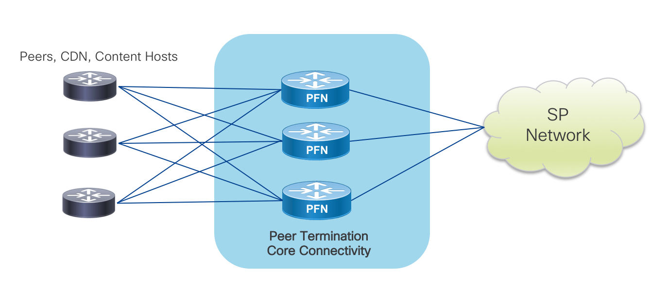
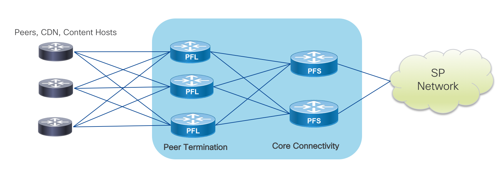
The Cisco Peering Fabric introduces two options for fabric topology and peer termination. The first, similar to more traditional peering deployments, collapses the Peer Termination and Core Connectivity network functions into a single physical device using the device’s internal fabric to connect each function. The second option utilizes a fabric separating the network functions into separate physical layers, connected via an external fabric running over standard Ethernet.
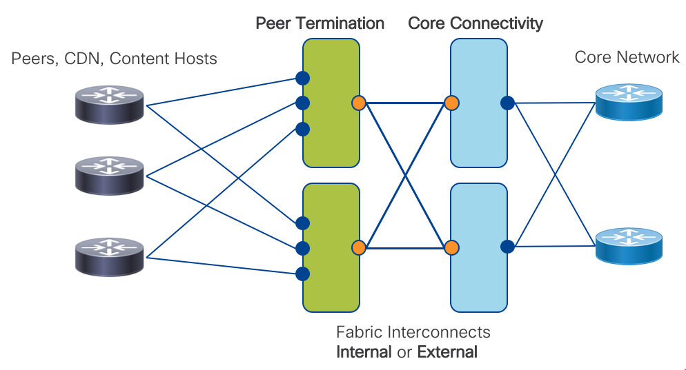
In many typical SP peering deployments, a traditional two-node setup is used where providers vertically upgrade nodes to support the higher capacity needs of the network. Some may employ technologies such as back to back or multi-chassis clusters in order to support more connections while keeping what seems like the operational footprint low. However, failures and operational issues occurring in these types of systems are typically difficult to troubleshoot and repair. They also require lengthy planning and timeframes for performing system upgrades. We introduce a horizontally scalable distributed peering fabric, the end result being more deterministic interface or node failures.
Minimizing the loss of peering capacity is very important for both ingress-heavy SPs and egress-heavy content providers. The loss of local peering capacity means traffic must ingress or egress a sub-optimal network port. Making a conscious design decision to spread peer connections, even to the same peer, across multiple edge nodes helps increase resiliency and limit traffic-affecting network events.
Platforms
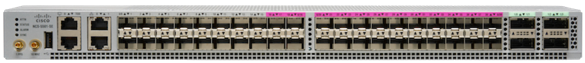
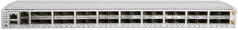
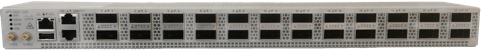
The Cisco NCS5500 platform is ideal for edge peer termination, given its high-density, large RIB and FIB scale, buffering capability, and IOS-XR software feature set. The NCS5500 is also space and power efficient with 36x100GE supporting up to 7.5M IPv4 routes in a 1RU fixed form factor or single modular line card. A minimal The Peering fabric can provide 36x100GE, 144x10GE, or a mix of non-blocking peering connections with full resiliency in 4RU. The fabric can also scale to support 10s of terabits of capacity in a single rack for large peering deployments. Fixed chassis are ideal for incrementally building a peering edge fabric, the NCS NC55-36X100GE-A-SE and NC55A1-24H are efficient high density building blocks which can be rapidly deployed as needed without installing a large footprint of devices day one. Deployments needing more capacity or interface flexibility such as IPoDWDM to extend peering can utilize the NCS5504 4-slot or NCS5508 8-slot modular chassis. If the peering location has a need for services termination the ASR9000 family or XRv-9000 virtual edge node can be incorporated into the fabric.
All NCS5500 routers also contain powerful Route Processors to unlock powerful telemetry and programmability. The Peering Fabric fixed chassis contain 1.6Ghz 8-core processors and 32GB of RAM. The latest NC55-RP-E for the modular NCS5500 chassis has a 1.9Ghz 6-core processor and 32G of RAM.
Control-Plane
The peering fabric design introduces a simplified control-plane built upon IPv4/IPv6 with Segment Routing. In the collapsed design, each peering node is connected to EBGP peers and upstream to the core via standard IS-IS, OSPF, and TE protocols, acting as a PE or LER in a provider network.
In the distributed design, network functions are separated. Peer Termination happens on Peering Fabric Leaf nodes. Peering Fabric Spine aggregation nodes are responsible for Core Connectivity and perform more advanced LER functions. The PFS routers use ECMP to balance traffic between PFL routers and are responsible for forwarding within the fabric and to the rest of the provider network. Each PFS acts as an LER, incorporated into the control-plane of the core network. The PFS, or alternatively vRRs, reflect learned peer routes from the PFL to the rest of the network. The SR control-plane supports several traffic engineering capabilities. EPE to a specific peer interface, PFL node, or PFS is supported. We also introduce the abstract peering concept where PFS nodes utilize a next-hop address bound to an anycast SR SID to allow traffic engineering on a per-peering center basis.
Telemetry
The Peering fabric design uses the rich telemetry available in IOS-XR and the NCS5500 platform to enable an unprecedented level of insight into network and device behavior. The Peering Fabric leverages Model-Driven Telemetry and NETCONF along with both standard and native YANG models for metric statistics collection. Telemetry configuration and applicable sensor paths have been identified to assist providers in knowing what to monitor and how to monitor it.
Automation
NETCONF and YANG using OpenConfig and native IOS-XR models are used to help automate peer configuration and validation. Cisco has developed specific Peering Fabric NSO service models to help automate common tasks such as peer interface configuration, peer BGP configuration, and adding physical interfaces to an existing peer bundle.
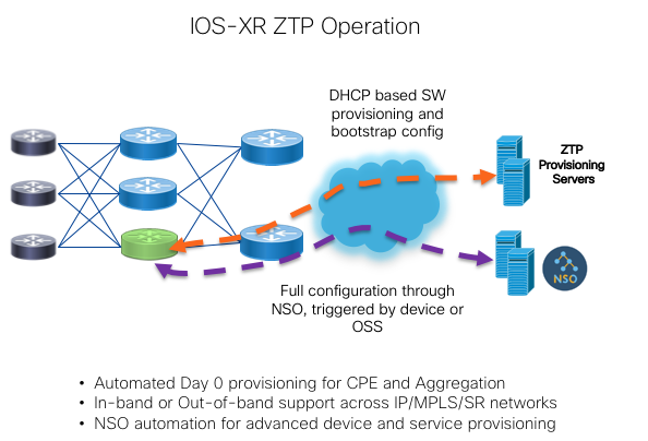
Zero Touch Provisioning
In addition to model-driven configuration and operation, Peering Fabric 1.5 also supports ZTP operation for automated device provisioning. ZTP is useful both in production as well as staging environments to automate initial device software installation, deploy an initial bootstrap configuration, as well as advanced functionality triggered by ZTP scripts. ZTP is supported on both out of band management interfaces as well as in-band data interfaces.
Advanced Security using BGP Flowspec and QPPB (1.5)
Release 1.5 of the Cisco Peering Fabric enhances the design by adding advanced security capabilities using BGP Flowspec and QoS Policy Propagation using BGP or QPPB. BGP Flowspec was standardized in RFC 5575 and defines additional BGP NLRI to inject packet filter information to receiving routers. BGP is the control-plane for disseminating the policy information while it is up to the BGP Flowspec receiver to implement the dataplane rules specified in the NLRI. At the Internet peering edge, DDoS protection has become extremely important, and automating the remediation of an incoming DDoS attack has become very important. Automated DDoS protection is only one BGP Flowspec use case, any application needing a programmatic way to create interface packet filters can make se use of its capabilities.
QPPB allows using BGP attributes as a match criteria in dataplane packet filters. Matching packets based on attributes like BGP community and AS Path allows service providers to create simplified edge QoS policies by not having to manage more cumbersome prefix lists or keep up to date when new prefixes are added. QPPB is supported in the peering fabric for destination prefix BGP attribute matching and has a number of use cases when delivering traffic from external providers to specific internal destinations.
Internet and Peering in a VRF
While Internet peering and carrying the Internet table in a provider network is typically done using the Global Routing Table (default VRF in IOS-XR) many modern networks are being built to isolate the GRT from the underlying infrastructure. In this case, the Internet global table is carried as a service just like any other VPN service, leaving the infrastructure layer protected from both the global Internet. Another application using VRFs is to simply isolate peers to specific VRFs in order to isolate the forwarding plane of each peer from each other and be able to control which routes a peer sees by the use of VPN route target communities as opposed to outbound routing policy. In this simplified use the case the global table is still carried in the default VRF, using IOS-XR capabilities to import and export routes to and from specific peer VRFs. Separating Internet and Peering routes into specific VRFs also gives flexibility in creating custom routing tables for specific customers, giving a service provider the flexibility to offer separate regional or global reach on the same network.
Internet in a VRF and Peering in a VRF for IPv4 and IPv6 are compatible with most Peering Fabric features. Specific caveats are document in the Appendix of the document.
Validated Design
The Peering Fabric Design control, management, and forwarding planes have undergone validation testing to ensure individual design features work as intended and the peering fabric as a whole performs without fault. Validation is done exceeding real-world scaling requirements to ensure the design fulfills its rule in existing networks with room for future growth.
Peering Fabric Use Cases
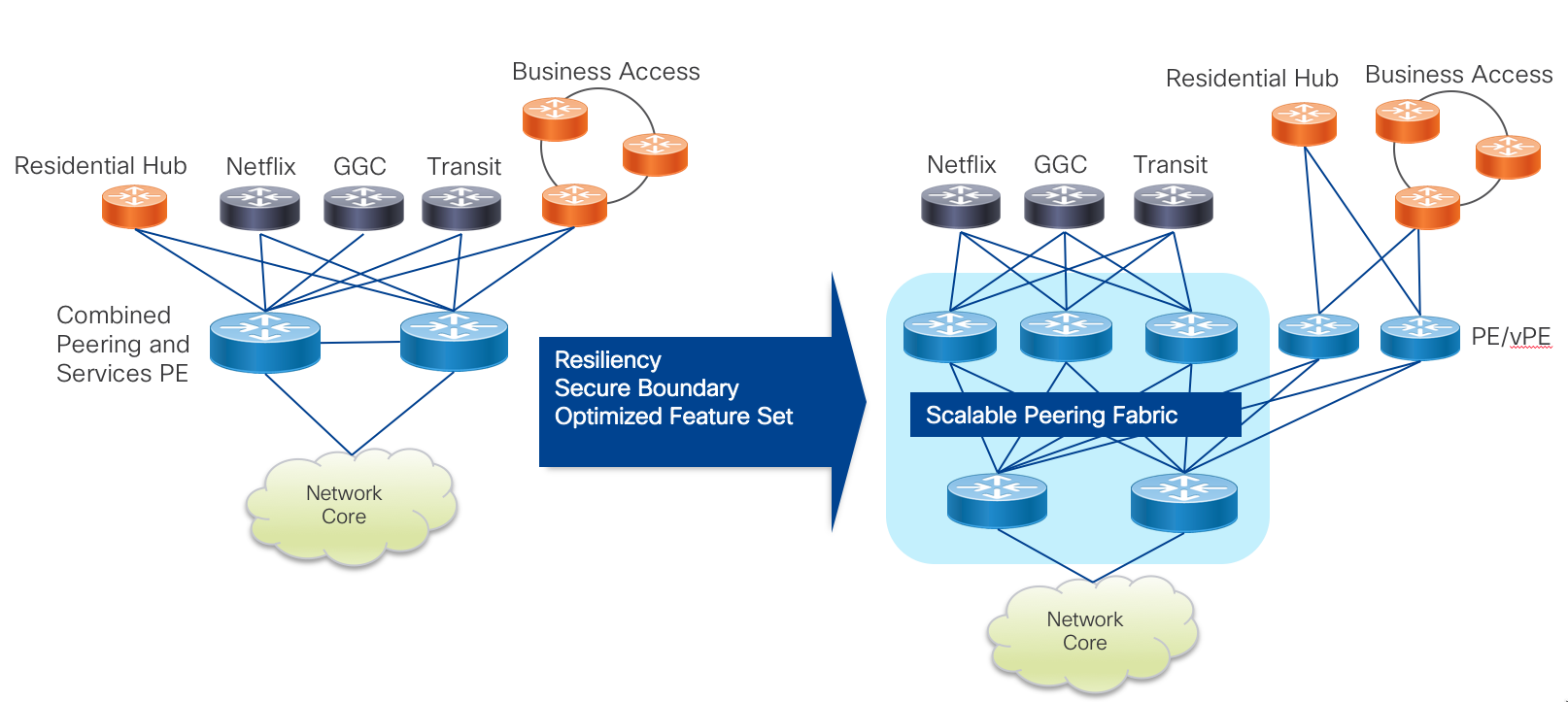
Traditional IXP Peering Migration to Peering Fabric
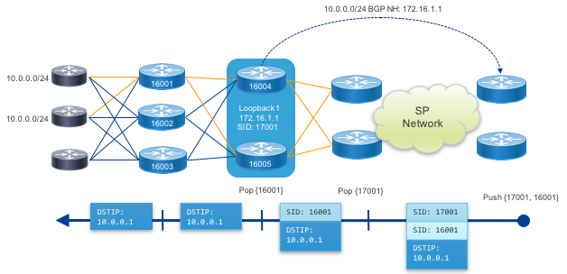
A traditional SP IXP design traditionally uses one or two large modular systems terminating all peering connections. In many cases, since providers are constrained on space and power they use a collapsed design where the minimal set of peering nodes not only terminates peer connections but also provides services and core connectivity to the location. The Peering Fabric uses best of breed high density, low footprint hardware requiring much less space than older generation modular systems. Many older systems provide densities at approximately 4x100GE per rack unit, while Peering Fabric PFL nodes start at 24x100GE or 36x100GE per 1RU with high FIB capability. Due to the superior space efficiency, there is no longer a limitation of using just a pair of nodes for these functions. In either a collapsed function or distributed function design, peers can be distributed across a number of devices to increase resiliency and lessen collateral impact when failures occur. The diagram below shows a fully distributed fabric, where peers are now distributed across three PFL nodes, each with full connectivity to upstream PFS nodes.
Peering Fabric Extension
In some cases, there may be peering facilities within close geographic proximity which need to integrate into a single fabric. This may happen if there are multiple 3rd party facilities in a close geographic area, each with unique peers you want to connect to. There may also be multiple independent peering facilities within a small geographic area you do not wish to install a complete peering fabric into. In those cases, connecting remote PFL nodes to a larger peering fabric can be done using optical transport or longer range gray optics.

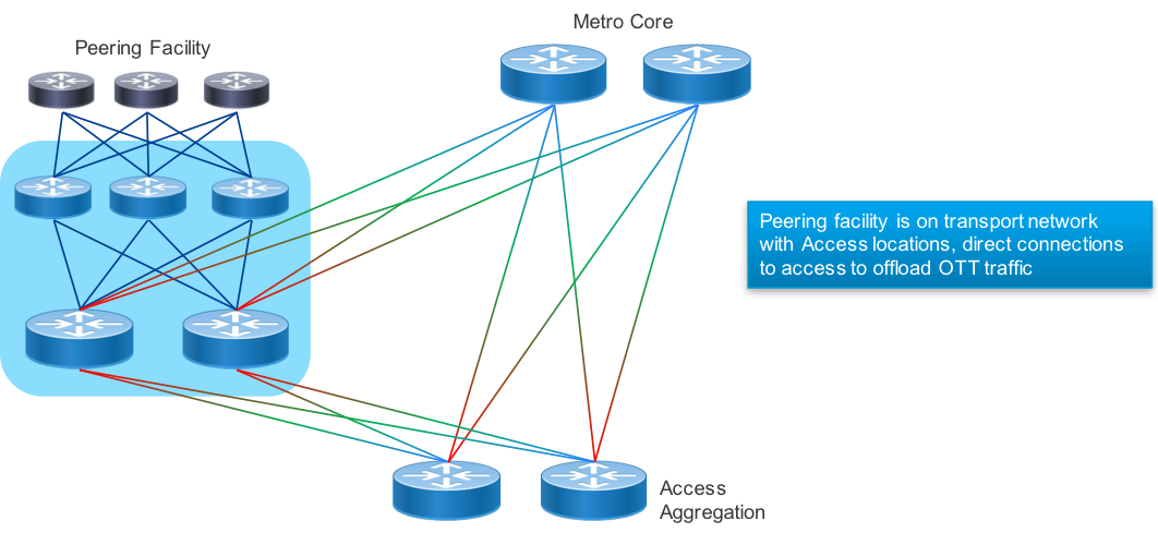
Localized Metro Peering and Content Delivery
In order to drive greater network efficiency, content sources should be places as close to the end destination as possible. Traditional wireline and wireless service providers have heavy inbound traffic from content providers delivering OTT video. Providers may also be providing their own IP video services to on-net and off-net destinations via a SP CDN. Peering and internal CDN equipment can be placed within a localized peer or content delivery center, connected via a common peering fabric. In these cases the PFS nodes connect directly to the metro core to enable delivery across the region or metro.

Express Peering Fabric
An evolution to localized metro peering is to interconnect the PFS peering nodes directly or a metro-wide peering core. The main driver for direct interconnection is minimizing the number of router and transport network interfaces traffic must pass through. High density optical muxponders such as the NCS1002 along with flexible photonic ROADM architectures enabled by the NCS2000 can help make the most efficient use of metro fiber assets.
Datacenter Edge Peering
In order to serve traffic as close to consumer endpoints as possible a provider may construct a peering edge attached to an edge or central datacenter. As gateway functions in the network become virtualized for applications such as vPE, vCPE, and mobile 5G, the need to attach Internet peering to the SP DC becomes more important. The Peering Fabric supports interconnected to the DC via the SP core or with the PFS nodes as leafs to the DC spine. These would act as traditional border routers in the DC design.

Peer Traffic Engineering with Segment Routing
Segment Routing performs efficient source routing of traffic across a provider network. Traffic engineering is particular applicable to peering as content providers look for ways to optimize egress network ports and eyeball providers work to reduce network hops between ingress and subscriber. There are also a number of advanced use cases based on using constraints to place traffic on optimal paths, such as latency. An SRTE Policy represents a forwarding entity within the SR domain mapping traffic to a specific network path, defined statically on the node or computed by an external PCE. An additional benefit of SR is the ability to source route traffic based on a node SID or an anycast SID representing a set of nodes. ECMP behavior is preserved at each point in the network, redundancy is simplified, and traffic protection is supplied using TI-LFA.
In the Low-Level Design we explore common peer engineering use cases. Much more information on Segment Routing technology and its future evolution can be found at http://segment-routing.net
Low-Level Design
Integrated Peering Fabric Reference Diagram
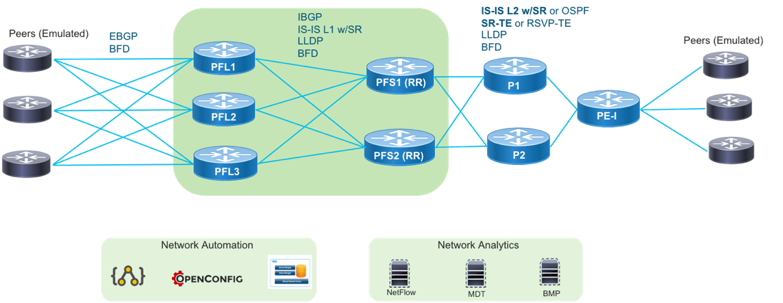
Distributed Peering Fabric Reference Diagram
Peering Fabric Hardware Detail
The NCS5500 family of routers provide high density, high routing scale, idea buffer sizes, and environmental efficiency to help providers satisfy any peering fabric use case. Due to high FIB scale, large buffers, and broad XR feature set, all prescribed hardware can serve in either a collapsed or distributed fabric. Further detailed information on each platform can be found at https://www.cisco.com/c/en/us/products/routers/network-convergence-system-5500-series/index.html.
NCS-5501-SE
The NCS 5501 is a 1RU fixed router with 40X10GE SFP+ and 4X100GE QSFP28 interfaces. The 5501 has IPv4 FIB scale of at least 2M routes. The 5501-SE is ideal as a peering leaf node when providers need 10GE interface flexibility such as ER, ZR, or DWDM.
NCS-55A1-36H-SE
The 55A1-36H-SE is a second generation 1RU NCS5500 fixed platform with 36 100GE QSFP28 ports operating at line rate. The –SE model contains an external TCAM increasing route scale to a minimum of 3M IPv4/512K IPv6 routes in its FIB. It also contains a powerful multi-core route processor with 64GB of RAM and an on-board 64GB SSD. Its high density, efficiency, and buffering capability make it ideal in 10GE or 100GE deployments. Peering fabrics can scale to much higher capacity 1RU at a time by simply adding additional 55A1-36H-SE spine nodes.
NCS-55A1-24H
The NCS-55A1-24H is a second generation 1RU NCS5500 fixed platform with 24 100GE QSFP28 ports. The device uses two 900GB NPUs, with 12X100GE ports connected to each NPU. The 55A1-24H uses a high scale NPU with a minimum of 1.3M IPv4/256K IPv6 routes. At just 675W it is ideal for 10GE peering fabric deployments with a migration path to 100GE connectivity. The 55A1-24H also has a powerful multi-core processor and 32GB of RAM.
NCS 5504 and 5508 Modular Chassis and NC55-36X100G-A-SE line card
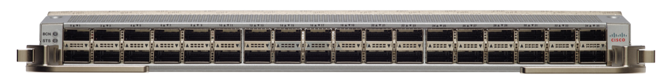


Very large peering fabric deployments or those needing interface flexibility such as IPoDWDM connectivity can use the modular NCS5500 series chassis. Large deployments can utilize the second-generation 36X100G-A-SE line card with external TCAM, supporting a minimum of 3M IPv4 routes.
Peer Termination Strategy
Often overlooked when connecting to Internet peers is determining a strategy to maximize efficiency and resiliency within a local peering instance. Often times a peer is connected to a single peering node even when two nodes exist for ease of configuration and coordination with the peering or transit partner. However, with minimal additional configuration and administration assisted by automation, even single peers can be spread across multiple edge peering nodes. Ideally, within a peering fabric, a peer is connected to each leaf in the fabric. In cases where this cannot be done, the provider should use capacity planning processes to balance peers and transit connections across multiple leafs in the fabric. The added resiliency leads to greater efficiency when failures do happen, with less reliance on peering capacity further away from the traffic destination.
Distributed Fabric Device Roles
PFL – Peering Fabric Leaf
The Peering Fabric Leaf is the node physically connected to external peers. Peers could be aggregation routers or 3rd party CDN nodes. In a deconstructed design the PFL is analogous to a line card in a modular chassis solution. PFL nodes can be added as capacity needs grow.
PFS – Peering Fabric Spine
The Peering Fabric Spine acts as an aggregation node for the PFLs and is also physical connected to the rest of the provider network. The provider network could refer to a metro core in the case of localized peering, a backbone core in relation to IXP peering, a DC spine layer in the case of DC peering.
Device Interconnection
In order to maximize resiliency in the fabric, each PFL node is connected to each PFS. While the design shown includes three PFLs and two PFS nodes, there could be any number of PFL and PFS nodes, scaling horizontally to keep up with traffic and interface growth. PFL nodes are not connected to each other, the PFS nodes provide the capacity for any traffic between those nodes. The PFS nodes are also not interconnected to each other, as no end device should terminate on the PFL, only other routers.
Capacity Scaling
Capacity of the peering fabric is scaled horizontally. The uplink capacity from PFL to PFS will be determine by an appropriate oversubscription factor determined by the service provider’s capacity planning exercises. The leaf/spine architecture of the fabric connects each PFL to each PFS with equal capacity. In steady-state operation traffic is balanced between the PFS and PFL in both directions, maximizing the total capacity. The entropy in peering traffic generally ensures equal distribution between either ECMP paths or bundle interface member links in the egress direction. More information can be found in the forwarding plane section of the document. An example deployment may have two NC55-36X100G-A-SE spine nodes and two NC55A1-24H leaf nodes. In a 100GE peer deployment scenario each leaf would support 14x100GE client connections and 5x100GE to each spine node. A 10GE deployment would support 72x10GE client ports and 3x100GE to each spine, at a 1.2:1 oversubscription ratio.
Peering Fabric Control Plane

PFL to Peer
The Peering Fabric Leaf is connected directly to peers via traditional EBGP. BFD may additionally be used for fault detection if agreed to by the peer. Each EBGP peer will utilize SR EPE to enable TE to the peer from elsewhere on the provider network.
PFL to PFS
PFL to Peering Fabric Spine uses widely deployed standard routing protocols. IS-IS is the prescribed IGP protocol within the peering fabric. Each PFS is configured with the same IS-IS L1 area. In the case where OSPF is being used as an IGP, the PFL nodes will reside in an OSPF NSSA area. The peering fabric IGP is SR-enabled with the loopback of each PFL assigned a globally unique SR Node SID. Each PFL also has an IBGP session to each PFR to distribute its learned EBGP routes upstream and learn routes from elsewhere on the provider network. If a provider is distributing routes from PFL to PFL or from another peering location to local PFLs it is important to enable the BGP “best-path-external” feature to ensure the PFS has the routing information to accelerate re-convergence if it loses the more preferred path.
Egress peer engineering will be enabled for EBGP peering connections, so that each peer or peer interface connected to a PFL is directly addressable by its AdJ-Peer-SID from anywhere on the SP network. Adj-Peer-SID information is currently not carried in the IGP of the network. If utilized it is recommended to distribute this information using BGP-LS to all controllers creating paths to the PFL EPE destinations.
Each PFS node will be configured with IBGP multipath so traffic is load balanced to PFL nodes and increase resiliency in the case of peer failure. On reception of a BGP withdraw update for a multipath route, traffic loss is minimized as the existing valid route is still programmed into the FIB.
PFS to Core
The PFS nodes will participate in the global Core control plane and act as the gateway between the peering fabric and the rest of the SP network. In order to create a more scalable and programmatic fabric, it is prescribed to use Segment Routing across the core infrastructure. IS-IS is the preferred protocol for transmitting SR SID information from the peering fabric to the rest of the core network and beyond. In deployments where it may be difficult to transition quickly to an all-SR infrastructure, the PFS nodes will also support OSPF and RSVP-TE for interconnection to the core. The PFS acts as an ABR or ASBR between the peering fabric and the larger metro or backbone core network.
SR Peer Traffic Engineering
Summary
SR allows a provider to create engineered paths to egress peering destinations or egress traffic destinations within the SP network. A stack of globally addressable labels is created at the traffic entry point, requiring no additional protocol state at midpoints in the network and preserving qualities of normal IGP routing such as ECMP at each hop. The Peering Fabric proposes end-to-end visibility from the PFL nodes to the destinations and vice-versa. This will allow a range of TE capabilities targeting a peering location, peering exit node, or as granular as a specific peering interface on a particular node. The use of anycast SIDs within a group of PFS nodes increases resiliency and load balancing capability.
Nodal EPE
Node EPE directs traffic to a specific peering node within the fabric. The node is targeted using first the PFS cluster anycast IP along with the specific PFL node SID.
Peer Interface EPE
This example uses an Egress Peer Engineering peer-adj-SID value assigned to a single peer interface. The result is traffic sent along this SR path will use only the prescribed interface for egress traffic.

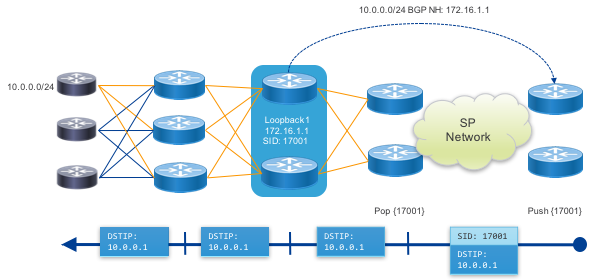
Abstract Peering
Abstract peering allows a provider to simply address a Peering Fabric by the anycast SIDs of its cluster of PFS nodes. In this case PHP is used for the anycast SIDs and traffic is simply forwarded as IP to the final destination across the fabric.
Peering Fabric Telemetry
Once a peering fabric is deployed, it is extremely important to monitor the health of the fabric as well as harness the wealth of data provided by the enhanced telemetry on the NCS5500 platform and IOS-XR. Through streaming data mechanisms such as Model-Driven Telemetry, BMP, and Netflow, providers can extract data useful for operations, capacity planning, security, and many other use cases. In the diagram below, the telemetry collection hosts could be a single system or distributed systems used for collection. The distributed design of the peering fabric enhances the ability to collect telemetry data from the fabric by distributing resources across the fabric. Each PFL or PFS contains a modern multi-core CPU and at least 32GB of RAM (64GB in NC55A1-36H-SE) to support not only built in telemetry operation but also 3rd party applications a service or content provider may want to deploy to the node for additional telemetry. Examples of 3rd party telemetry applications include those storing temporary data for root-cause analysis if a node is isolated from the rest of the network or performance measurement applications.
The peering fabric also fully supports traditional collections methods such as SNMP, and NETCONF using YANG models to integrate with legacy systems.
Telemetry Diagram

Model-Driven Telemetry
MDT uses standards-based or native IOS-XR YANG data models to stream operational state data from deployed devices. The ability to push statistics and state data from the device adds capabilities and efficiency not found using traditional SNMP. Sensors and collection hosts can be configured statically on the host (dial-out) or the set of sensors, collection hosts, and their attributes can be managed off-box using OpenConfig or native IOS-XR YANG models. Pipeline is Cisco’s open source collector, which can take MDT data as an input and output it via a plugin architecture supporting scalable messages buses such as Kafka, or directly to a TSDB such as InfluxDB or Prometheus. The appendix contains information about MDT YANG paths relevant to the peering fabric and their applicability to PFS and PFL nodes.
BGP Monitoring Protocol
BMP, defined in RFC7854, is a protocol to monitor BGP RIB information, updates, and protocol statistics. BMP was created to alleviate the burden of collecting BGP routing information using inefficient mechanisms like screen scraping. BMP has two primary modes, Route Monitoring mode and Route Mirroring mode. The monitoring mode will initially transmit the adj-rib-in contents per-peer to a monitoring station, and continue to send updates as they occur on the monitored device. Setting the L bits on the RM header to 1 will convey this is a post-policy route, 0 will indicate pre-policy. The mirroring mode simply reflects all received BGP messages to the monitoring host. IOS-XR supports sending pre and post policy routing information and updates to a station via the Route Monitoring mode. BMP can additionally send information on peer state change events, including why a peer went down in the case of a BGP event.
There are drafts in the IETF process led by Cisco to extend BMP to report additional routing data, such as the loc-RIB and per-peer adj-RIB-out. Local-RIB is the full device RIB include ng received BGP routes, routes from other protocols, and locally originated routes. Adj-RIB-out will add the ability to monitor routes advertised to peers pre and post routing policy.
Netflow / IPFIX
Netflow was invented by Cisco due to requirements for traffic visibility and accounting. Netflow in its simplest form exports 5-tuple data for each flow traversing a Netflow-enabled interface. Netflow data is further enhanced with the inclusion of BGP information in the exported Netflow data, namely AS_PATH and destination prefix. This inclusion makes it possible to see where traffic originated by ASN and derive the destination for the traffic per BGP prefix. The latest iteration of Cisco Netflow is Netflow v9, with the next-generation IETF standardized version called IPFIX (IP Flow Information Export). IPFIX has expanded on Netflow’s capabilities by introducing hundreds of entities.
Netflow is traditionally partially processed telemetry data. The device itself keeps a running cache table of flow entries and counters associated with packets, bytes, and flow duration. At certain time intervals or event triggered, the flow entries are exported to a collector for further processing. The type 315 extension to IPFIX, supported on the NCS5500, does not process flow data on the device, but sends the raw sampled packet header to an external collector for all processing. Due to the high bandwidth, PPS rate, and large number of simultaneous flows on Internet routers, Netflow samples packets at a pre-configured rate for processing. Typical sampling values on peering routers are 1 in 8192 packets, however customers implementing Netflow or IPFIX should work with Cisco to fine tune parameters for optimal data fidelity and performance.
Automation and Programmability
Cisco NSO Modules
Cisco Network Services Orchestrator is a widely deployed network automation and orchestration platform, performing intent-driven configuration and validation of networks from a single source of truth configuration database. The Peering design includes a Cisco NSO modules to perform specific peering tasks such as peer turn-up, peer modification, deploying routing policy and ACLs to multiple nodes, providing a jumpstart to peering automation. The following table highlights the currently available Peering NSO services. The current peering service models use the IOS-XR CLI NED and are validated with NSO 4.5.5.
| Service | Description |
|---|---|
| peering-service | Manage full BGP and Interface Configuration for EBGP Peers |
| peering-acl | Manage infrastructure ACLs referenced by the peering service |
| prefix-set | Manage IOS-XR prefix-sets |
| as-path-set | Manage IOS-XR as-path sets |
| route-policy | Manage XR routing policies for deployment to multiple peering nodes |
| peering-common | A set of services to manage as-path sets, community sets, and static routing policies |
| drain-service | Service to automate draining traffic away from a node under maintenance |
| telemetry | Service to enable telemetry sensors and export to collector |
| bmp | Service to enable BMP on configured peers and export to monitoring station |
| netflow | Service to enable Netflow on configured peer interfaces and export to collector |
| PFL-to-PFS-Routing | Configures IGP and BGP routing between PFL and PFS nodes |
| PFS-Global-BGP | Configures global BGP parameters for PFS nodes |
| PFS-Global-ISIS | Configures global IS-IS parameters for PFS nodes |
Netconf
Netconf is an industry standard method for configuration network devices. Standardized in RFC 6241, Netconf has standard Remote Procedure Calls (RPCs) to manipulate configuration data and retrieving state data. Netconf on IOS-XR supports the candidate datastore, meaning configuration must be explicitly committed for application to the running configuration.
YANG Model Support
While Netconf created standard RPCs for managing configuration on a device, it did not define a language for expressing configuration. The configuration syntax communicated by Netconf followed the typical CLI configuration, proprietary for each network vendor XML formatted without following any common semantics. YANG or Yet Another Network Grammar, is a modeling language to express configuration using standard elements such as containers, groups, lists, and endpoint data called leafs. YANG 1.0 was defined in RFC 6020 and updated to version 1.1 in RFC 7950. Vendors cover the majority of device configuration and state using Native YANG models unique to each vendor, but the industry is headed towards standardized models where applicable. Groups such as OpenConfig and the IETF are developing standardized YANG models allowing operators to write a configuration once across all vendors. Cisco has implemented a number of standard OpenConfig network models relevant to peering including the BGP protocol, BGP RIB, and Interfaces model.
The appendix contains information about YANG paths relevant to configuring the peering fabric and their applicability to PFS and PFL nodes.
3rd Party Hosted Applications
IOS-XR starting in 6.0 runs on an x86 64-bit Linux foundation. The move to an open and well supported operating system, with XR components running on top of it, allows network providers to run 3rd party applications directly on the router. There are a wide variety of applications which can run on the XR host, with fast path interfaces in and out of the application. Example applications are telemetry collection, custom network probes, or tools to manage other portions of the network within a location.
XR Service Layer API
The XR service layer API is a gRPC based API to extract data from a device as well as provide a very fast programmatic path into the router’s runtime state. One use case of SL API in the peering fabric is to directly program FIB entries on a device, overriding the default path selection. Using telemetry extracted from a peering fabric, an external controller can use the data and additional external constraints to programmatically direct traffic across the fabric. SL API also supports transmission of event data via subscriptions.
Recommended Device and Protocol Configuration
Overview
The following configuration guidelines will step through the major components of the device and protocol configuration specific to the peering fabric and highlight non-default configuration recommended for each device role and the reasons behind those choices. Complete example configurations for each role can be found in the Appendix of this document. Configuration specific to telemetry is covered in section 4.
Common Node Configuration
The following configuration is common to both PFL and PFS NCS5500 series nodes.
Enable LLDP Globally
lldp
PFS Nodes
As the PFS nodes will integrate into the core control-plane, only recommended configuration for connectivity to the PFL nodes is given.
IGP Configuration
router isis pf-internal-core
 set-overload-bit on-startup wait-for-bgp
 is-type level-1-2
 net <L2 NET>
 net <L1 PF NET>
 log adjacency changes
 log pdu drops
 lsp-refresh-interval 65000  ;Maximum refresh interval to reduce IS-IS protocol traffic
 max-lsp-lifetime 65535 ;Maximum LSP lifetime to reduce IS-IS protocol traffic
 lsp-password hmac-md5 <password> ;Set LSP password, enhance security
 address-family ipv4 unicast
  metric-style wide
  segment-routing mpls ;Enable segment-routing for IS-IS
  maximum-paths 32 ;Set ECMP path limit
 address-family ipv6 unicast
  metric-style wide
  maximum-paths 32
!
interface Loopback0
 passive
 address-family ipv4 unicast
  metric 10
  prefix-sid index <globally unique index>
address-family ipv6 unicast
  metric 10
!
interface HundredGigE0/0/0
 point-to-point
 circuit-type level-1
 hello-password hmac-md5 <password>
 bfd minimum-interval 100
 bfd multiplier 3
 bfd fast-detect ipv4
 bfd fast-detect ipv6
 address-family ipv4 unicast
  metric 10
   fast-reroute per-prefix ti-lfa ;Enable topology-independent loop-free-alternates on a per-prefix basis
 address-family ipv6 unicast
  metric 10
Segment Routing Traffic Engineering
In IOS-XR there are two mechanisms for configuring SR-TE. Prior to IOS-XR 6.3.2 SR-TE was configured using the MPLS traffic engineering tunnel interface configuration. Starting in 6.3.2 SR-TE can now be configured using the more flexible SR-TE Policy model. The following examples show how to define a static SR-TE path from PFS node to exit PE node using both the legacy tunnel configuration model as well as the new SR Policy model.
Paths to PE exit node being load balanced across two static P routers using legacy tunnel config
explicit-path name PFS1-P1-PE1-1
 index 1 next-address 192.168.12.1
 index 2 next-address 192.168.11.1
!
explicit-path name PFS1-P2-PE1-1
 index 1 next-label 16221
 index 2 next-label 16511
!
interface tunnel-te1
 bandwidth 1000
 ipv4 unnumbered Loopback0
 destination 192.168.11.1
 path-option 1 explicit name PFS1-P1-PE1-1 segment-routing
!
interface tunnel-te2
 bandwidth 1000
 ipv4 unnumbered Loopback0
 destination 192.168.11.2
 path-option 1 explicit name PFS1-P2-PE1-1 segment-routing
IOS-XR 6.3.2+ SR Policy Configuration
segment-routing
traffic-eng
  segment-list PFS1-P1-PE1-SR-1
   index 1 mpls label 16211
   index 2 mpls label 16511
  !
  segment-list PFS1-P2-PE1-SR-1
   index 1 mpls label 16221
   index 2 mpls label 16511
  !
  policy pfs1_pe1_via_p1
   binding-sid mpls 900001
   color 1 end-point ipv4 192.168.11.1
   candidate-paths
    preference 150
     explicit segment-list PFS1-P1-PE1-SR-1
      weight 1
     !
    !
   !
  !
  policy pfs1_pe1_via_p2
   binding-sid mpls 900002
   color 2 end-point ipv4 192.168.11.1
   candidate-paths
    preference 150
     explicit segment-list PFS1-P1-PE1-SR-1
      weight 1
     !
    !
   !
  !
BGP Global Configuration
bgp router-id <Lo0 IP>
bgp bestpath aigp ignore ;Ignore AIGP community when sent by peer
bgp bestpath med always ;Compare MED values even when AS_PATH doesn’t match
bgp bestpath as-path multipath-relax ;Use multipath even if AS_PATH is longer
address-family ipv4 unicast
 additional-paths receive
 maximum-paths ibgp 32 ;set maximum retained IBGP paths to 32
 maximum-paths ebgp 32 ;set maximum retained EBGP paths to 32
!
address-family ipv6 unicast
 additional-paths receive
 bgp attribute-download
 maximum-paths ibgp 32
 maximum-paths ebgp 32
!
address-family link-state link-state ;Enable BGP-LS AF
Model-Driven Telemetry Configuration
The configuration below creates two sensor groups, one for BGP data and one for Interface counters. Each is added to a separate subscription, with the BGP data sent every 60 seconds and the interface data sent every 30 seconds. A single destination is used, however multiple destinations could be configured. The sensors and timers provided are for illustration only.
telemetry model-driven
 destination-group mdt-dest-1
  vrf default
  address-family ipv4 <dest IP> <dest-port>
   encoding <gpb | self-describing-gbp>
   protocol <tcp | grpc>
  !
 !
 sensor-group peering-pfl-bgp
  sensor-path openconfig-bgp:bgp/neighbors
 !
 sensor-group peering-pfl-interface
  sensor-path openconfig-platform:components
  sensor-path openconfig-interfaces:interfaces
  sensor-path Cisco-IOS-XR-pfi-im-cmd-oper:interfaces/interface-xr/interface
  sensor-path Cisco-IOS-XR-drivers-media-eth-oper/ethernet-interface/interfaces/interface/phy-info
  sensor-path Cisco-IOS-XR-infra-statsd-oper:infra-statistics/interfaces/interface/latest/generic-counters
 !
 subscription peering-pfl-sub-bgp
  sensor-group-id peering-pfl-bgp sample-interval 60000
  destination-id mdt-dest-1
 !
 subscription peering-pfl-sub-interface
  sensor-group-id peering-pfl-interface sample-interval 30000
  destination-id mdt-dest-1
PFL Nodes
Peer QoS Policy
Policy applied to edge of the network to rewrite any incoming DSCP value to 0.
policy-map peer-qos-in
 class class-default
  set dscp default
 !
 end-policy-map
!
Peer Infrastructure ACL
See the Security section of the document for recommended best practices for ingress and egress infrastructure ACLs.
access-group v4-infra-acl-in
access-group v6-infra-acl-in
access-group v4-infra-acl-out
access-group v6-infra-acl-out
Peer Interface Configuration
interface TenGigE0/0/0/0
 description “external peer”
 service-policy input peer-qos-in ;Explicit policy to rewrite DSCP to 0
 lldp transmit disable :Do not run LLDP on peer connected interfaces
 lldp receive disable :Do not run LLDP on peer connected interfaces
 ipv4 access-group v4-infra-acl-in :IPv4 Ingress infrastructure ACL
 ipv4 access-group v4-infra-acl-out :IPv4 Egress infrastructure ACL, BCP38 filtering
 ipv6 access-group v6-infra-acl-in :IPv6 Ingress infrastructure ACL
 ipv6 access-group v6-infra-acl-out :IPv6 Egress infrastructure ACL, BCP38 filtering
IS-IS IGP Configuration
router isis pf-internal
 set-overload-bit on-startup wait-for-bgp
 is-type level-1
 net <L1 Area NET>
 log adjacency changes
 log pdu drops
 lsp-refresh-interval 65000  ;Maximum refresh interval to reduce IS-IS protocol traffic
 max-lsp-lifetime 65535 ;Maximum LSP lifetime to reduce IS-IS protocol traffic
 lsp-password hmac-md5 <password> ;Set LSP password, enhance security
 address-family ipv4 unicast
  metric-style wide
  segment-routing mpls ;Enable segment-routing for IS-IS
  maximum-paths 32 ;Set ECMP path limit
 address-family ipv6 unicast
  metric-style wide
  maximum-paths 32
!
interface Loopback0
 passive
 address-family ipv4 unicast
  metric 10
  prefix-sid index <globally unique index>
address-family ipv6 unicast
  metric 10
!
interface HundredGigE0/0/0
 point-to-point
 circuit-type level-1
 hello-password hmac-md5 <password>
 bfd minimum-interval 100
 bfd multiplier 3
 bfd fast-detect ipv4
 bfd fast-detect ipv6
 address-family ipv4 unicast
  metric 10
   fast-reroute per-prefix ti-lfa ;Enable topology-independent loop-free-alternates on a per-prefix basis
 address-family ipv6 unicast
  metric 10
BGP Add-Path Route Policy
route-policy advertise-all ;Create policy for add-path advertisements
  set path-selection all advertise
end-policy
BGP Global Configuration
bgp router-id <Lo0 IP>
bgp bestpath aigp ignore ;Ignore AIGP community when sent by peer
bgp bestpath med always ;Compare MED values even when AS_PATH doesn’t match
bgp bestpath as-path multipath-relax ;Use multipath even if AS_PATh is longer
address-family ipv4 unicast
 bgp attribute-download  ;Enable BGP information for Netflow/IPFIX export
 additional-paths send
 additional-paths selection route-policy advertise-all ;Advertise all equal-cost IPv4 NLRI to PFS
 maximum-paths ibgp 32 ;set maximum retained IBGP paths to 32
 maximum-paths ebgp 32 ;set maximum retained EBGP paths to 32
!
address-family ipv6 unicast
 additional-paths send
 additional-paths receive
 additional-paths selection route-policy advertise-all ;Advertise all equal-cost IPv6 NLRI to PFS
 bgp attribute-download
 maximum-paths ibgp 32
 maximum-paths ebgp 32
!
address-family link-state link-state ;Enable BGP-LS AF
EBGP Peer Configuration
session-group peer-session
  ignore-connected-check :Allow loopback peering over ECMP w/o EBGP Multihop
  egress-engineering :Allocate adj-peer-SID
  bmp-activate server 1 :Optional send BMP data to receiver 1

af-group v4-af-peer address-family ipv4 unicast
 soft-reconfiguration inbound always :Store inbound routes for operational purposes
 multipath :Store multiple paths if using ECMP to neighbor
 maximum-prefix 1000 80;Set maximum inbound prefixes, warning at 80% threshold

af-group v6-af-peer
 soft-reconfiguration inbound always :Store inbound routes for operational purposes
 multipath :Store multiple paths if using ECMP to neighbor
 maximum-prefix 100 80 :Set maximum inbound prefixes, warning at 80% threshold

neighbor-group v4-peer
  use session-group peer-session
  dmz-link-bandwidth ;Propagate external link BW
  address-family ipv4 unicast af-group v4-af-peer

neighbor-group v6-peer
  use session-group peer-session
  dmz-link-bandwidth
  address-family ipv6 unicast af-group v6-af-peer

neighbor 1.1.1.1
 description "ext-peer;12345"
 remote-as 12345
 use neighbor-group v4-peer
 address-family ipv4 unicast
 route-policy v4-peer-in(12345) in
 route-policy v4-peer-out(12345) out

neighbor 2001:dead:b33f:0:1:1:1:1
 description "ext-peer;12345"
 remote-as 12345
 use neighbor-group v6-peer
 address-family ipv6 unicast
 route-policy v6-peer-in(12345) in
 route-policy v6-peer-out(12345) out
PFL to PFS IBGP Configuration
session-group pfs-session
 bmp-activate server 1 :Optional send BMP data to receiver 1
 update-source Loopback0 :Set BGP session source address to Loopback0 address


af-group v4-af-pfs address-family ipv4 unicast
 next-hop-self :Set next-hop to Loopback0 address
 soft-reconfiguration inbound always :Store inbound routes for operational purposes
 multipath :Store multiple paths if using ECMP to neighbor
 route-policy v4-pfs-in in
 route-policy v4-pfs-out out

af-group v6-af-pfs
 next-hop-self :Set next-hop to Loopback0 address
 soft-reconfiguration inbound always :Store inbound routes for operational purposes
 multipath :Store multiple paths if using ECMP to neighbor
 route-policy v6-pfs-in in
 route-policy v6-pfs-out out

neighbor-group v4-pfs
  !
  use session-group pfs-session
  address-family ipv4 unicast af-group v4-af-pfs

neighbor-group v6-pfs
  !
  use session-group pfs-session
  address-family ipv6 unicast af-group v6-af-pfs

neighbor <PFS IP>
 description "PFS #1"
 remote-as <local ASN>
 use neighbor-group v4-pfs
Netflow/IPFIX Configuration
flow exporter-map nf-export
 version v9
  options interface-table timeout 60
  options sampler-table timeout 60
  template timeout 30
 !
 transport udp <port>
 source Loopback0
 destination <dest>

flow monitor-map flow-monitor-ipv4
 record ipv4
 option bgpattr
 exporter nf-export
 cache entries 50000
 cache timeout active 60
 cache timeout inactive 10
!
flow monitor-map flow-monitor-ipv6
 record ipv6
 option bgpattr
 exporter nf-export
 cache timeout active 60
 cache timeout inactive 10
!
flow monitor-map flow-monitor-mpls
 record mpls ipv4-ipv6-fields
 option bgpattr
 exporter nf-export
 cache timeout active 60
 cache timeout inactive 10

sampler-map nf-sample-8192
 random 1 out-of 8192
Peer Interface
interface Bundle-Ether100
 flow ipv4 monitor flow-monitor-ipv4 sampler nf-sample-8192 ingress
 flow ipv6 monitor flow-monitor-ipv6 sampler nf-sample-8192 ingress
 flow mpls monitor flow-monitor-mpls sampler nf-sample-8192 ingress
PFS Upstream Interface
interface HundredGigE0/0/0/100
 flow ipv4 monitor flow-monitor-ipv4 sampler nf-sample-8192 ingress
 flow ipv6 monitor flow-monitor-ipv6 sampler nf-sample-8192 ingress
 flow mpls monitor flow-monitor-mpls sampler nf-sample-8192 ingress
Model-Driven Telemetry Configuration
The configuration below creates two sensor groups, one for BGP data and one for Interface counters. Each is added to a separate subscription, with the BGP data sent every 60 seconds and the interface data sent every 30 seconds. A single destination is used, however multiple destinations could be configured. The sensors and timers provided are for illustration only.
telemetry model-driven
 destination-group mdt-dest-1
  vrf default
  address-family ipv4 <dest IP> <dest-port>
   encoding <gpb | self-describing-gbp>
   protocol <tcp | grpc>
  !
 !
 sensor-group peering-pfl-bgp
  sensor-path openconfig-bgp:bgp/neighbors
 !
 sensor-group peering-pfl-interface
  sensor-path openconfig-platform:components
  sensor-path openconfig-interfaces:interfaces
  sensor-path Cisco-IOS-XR-pfi-im-cmd-oper:interfaces/interface-xr/interface
  sensor-path Cisco-IOS-XR-drivers-media-eth-oper/ethernet-interface/interfaces/interface/phy-info
  sensor-path Cisco-IOS-XR-infra-statsd-oper:infra-statistics/interfaces/interface/latest/generic-counters
 !
 subscription peering-pfl-sub-bgp
  sensor-group-id peering-pfl-bgp sample-interval 60000
  destination-id mdt-dest-1
 !
 subscription peering-pfl-sub-interface
  sensor-group-id peering-pfl-interface sample-interval 30000
  destination-id mdt-dest-1
Abstract Peering Configuration
Abstract peering uses qualities of Segment Routing anycast addresses to allow a provider to steer traffic to a specific peering fabric by simply addressing a node SID assigned to all PFS members of the peering cluster. All of the qualities of SR such as midpoint ECMP and TI-LFA fast protection are preserved for the end to end BGP path, improving convergence across the network to the peering fabric. Additionally, through the use of SR-TE Policy, source routed engineered paths can be configured to the peering fabric based on business logic and additional path constraints.
PFS Configuration
Only the PFS nodes require specific configuration to perform abstract peering. Configuration shown is for example only with IS-IS configured as the IGP carrying SR information. The routing policy setting the next-hop to the AP anycast SID should be incorporated into standard IBGP outbound routing policy.
interface Loopback1
 ipv4 address x.x.x.x/32
 ipv6 address x:x:x:x::x/128

router isis <ID>
 passive
 address-family ipv4 unicast
  prefix-sid absolute <Global IPv4 AP Node SID>
 address-family ipv6 unicast
  prefix-sid absolute <Global IPv6 AP Node SID>

route-policy v4-abstract-ibgp-out
 set next-hop <Loopback1 IPv4 address>

route-policy v6-abstract-ibgp-out
 set next-hop <Loopback1 IPv6 address>

router bgp <ASN>
 ibgp policy out enforce-modifications ;Enables a PFS node to set a next-hop address on routes reflected to IBGP peers

router bgp <ASN>
 neighbor x.x.x.x
  address-family ipv4 unicast route-policy v4-abstract-ibgp-out
 neighbor x:x:x:x::x
  address-family ipv6 unicast route-policy v6-abstract-ibgp-out
BGP Flowspec Configuration and Operation
BGP Flowspec consists of two different node types. The BGP Flowspec Server is where Flowspec policy is defined and sent to peers via BGP sessions with the BGP Flowspec IPv4 and IPv6 AFI/SAFI enabled. The BGP Flowspec Client receives Flowspec policy information and applies the proper dataplane match and action criteria via dynamic ACLs applied to each router interface. By default, IOS-XR applies the dynamic policy to all interfaces, with an interface-level configuration setting used to disable BGP Flowspec on specific interfaces.
In the Peering Fabric, PFL nodes will act as Flowspec clients. The PFS nodes may act as Flowspec servers, but will never act as clients.
Flowspec policies are typically defined on an external controller to be advertised to the rest of the network. The XRv-9000 virtual router works well in these instances. If one is using an external element to advertise Flowspec policies to the peering fabric, they should be advertised to the PFS nodes which will reflect them to the PFL nodes. In the absence of an external policy injector Flowspec policies can be defined on the Peering Fabric PFS nodes for advertisement to all PFL nodes. IPv6 Flowspec on the NCS5500 requires the use of the following global command, followed by a device reboot.
hw-module profile flowspec ipv6-enable
Enabling BGP Flowspec Address Families on PFS and PFL Nodes
Following the standard Peering Fabric BGP group definitions the following new groups are augmented. The following configuration assumes the PFS node is the BGP Flowspec server.
PFS
router bgp <ASN>
address-family ipv4 flowspec
address-family ipv6 flowspec

af-group v4-flowspec-af-pfl address-family ipv4 flowspec
   multipath
   route-reflector-client
   next-hop-self

af-group v6-flowspec-af-pfl address-family ipv4 flowspec
   multipath
   route-reflector-client
   next-hop-self

neighbor-group v4-pfl
   address-family ipv4 flowspec
      use af-group v4-flowspec-af-pfl

neighbor-group v6-pfl
   address-family ipv6 flowspec
      use af-group v6-flowspec-af-pfl
PFL
router bgp <ASN>
address-family ipv4 flowspec
address-family ipv6 flowspec

af-group v4-flowspec-af-pfs address-family ipv4 flowspec
   multipath

af-group v6-flowspec-af-pfs address-family ipv4 flowspec
   multipath

neighbor-group v4-pfs
   address-family ipv4 flowspec
      use af-group v4-flowspec-af-pfl

neighbor-group v6-pfs
   address-family ipv6 flowspec
      use af-group v6-flowspec-af-pfl
BGP Flowspec Server Policy Definition
Policies are defined using the standard IOS-XR QoS Configuration, the first example below matches the recent memcached DDoS attack and drops all traffic. Additional examples are given covering various packet matching criteria and actions.
class-map type traffic match-all memcached
 match destination-port 11211
 match protocol udp tcp
 match destination-address ipv4 10.0.0.0 255.255.255.0
 end-class-map
!
!
policy-map type pbr drop-memcached
 class type traffic memcached
  drop
 !
 class type traffic class-default
 !
 end-policy-map
class-map type traffic match-all icmp-echo-flood
 match protocol icmp
 match ipv4 icmp type 8
 match destination-address ipv4 10.0.0.0 255.255.255.0
 end-class-map
!
!
policy-map type pbr limit-icmp-echo
 class type traffic memcached
  police rate 100 kbps
 !
 class type traffic class-default
 !
 end-policy-map
class-map type traffic match-all dns
 match protocol udp
 match source port 53
 end-class-map
!
!
policy-map type pbr redirect-dns
 class type traffic dns
  police rate 100 kbps
 !
 class type traffic class-default
   redirect nexthop 1.1.1.1
   redirect nexthop route-target 1000:1
 !
 end-policy-map
BGP Flowspec Server Enablement
The following global configuration will enable the Flowspec server and advertise the policy via the BGP Flowspec NLRI
flowspec
 address-family ipv4
  service-policy type pbr drop-memcached
BGP Flowspec Client Configuration
The following global configuration enables the BGP Flowspec client function and installation of policies on all local interfaces. Flowspec can be disabled on individual interfaces using the [ipv4|ipv6] flowspec disable command in interface configuration mode.
flowspec
 address-family ipv4
  local-install interface-all
QPPB Configuration and Operation
QoS Policy Propagation using BGP is described in more detail in the Security section.
QPPB applies standard QoS policies to packets matching BGP prefix criteria such as BGP community or AS Path. QPPB is supported for both IPv4 and IPv6 address families and packets. QPPB on the NCS5500 supports matching destination prefix attributes only.
QPPB configuration starts with a standard RPL route policy that matches BGP attributes and sets a specific QoS group based on that criteria. This routing policy is applied to each address-family as a table-policy in the global BGP configuration. A standard MQC QoS policy is then defined using the specific QoS groups as match criteria to apply additional QoS behavior such as filtering, marking, or policing. This policy is applied to a logical interface, with a specific QPPB command used to enable the propagation of BGP data as part of the dataplane ACL packet match criteria.
IPv6 QPPB on the NCS5500 requires the use of the following global command, followed by a device reboot.
hw-module profile qos ipv6 short
Routing Policy Configuration
route-policy qppb-test
  if community matches-every (1000:1) then
    set qos-group 1
  endif
  if community matches-every (1000:2) then
    set qos-group 2
  endif
end-policy
Global BGP Configuration
router bgp <ASN>
 address-family ipv4 unicast
   table-policy qppb-test
 address-family ipv6 unicast
   table-policy qppb-test
QoS Policy Definition
class-map match-any qos-group-1
  match qos-group 1
  end-class-map

class-map match-any qos-group-2
  match qos-group 2
  end-class-map

policy-map remark-peer-traffic
 class qos-group1
  set precedence 5
  set mpls experimental imposition 5
 !
 class qos-group2
  set precedence 3
  set mpls experimental imposition 3
 !
 class class-default
 !
 end-policy-map
Interface-Level Configuration
interface gigabitethernet0/0/0/1
   service-policy input remark-peer-traffic
   ipv4 bgp policy propagation input qos-group destination
   ipv6 bgp policy propagation input qos-group destination
Security
Peering by definition is at the edge of the network, where security is mandatory. While not exclusive to peering, there are a number of best practices and software features when implemented will protect your own network as well as others from malicious sources within your network.
Peering and Internet in a VRF
Using VRFs to isolate peers and the Internet routing table from the infrastructure can enhance security by keeping internal infrastructure components separate from Internet and end user reachability. VRF separation can be done one of three different ways:
- Separate each peer into its own VRF, use default VRF on SP Network
- Single VRF for all “Internet” endpoints, including peers
- Separate each peer into its own VRF, and use a separate “Internet” VRF
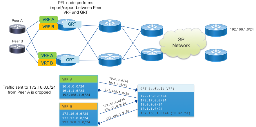
VRF per Peer, default VRF for Internet
In this method each peer, or groups of peers, are configured under separate VRFs. The SP carries these and all other routes via the default VRF in IOS-XR commonly known as the Global Routing Table. The VPNv4 and VPNv6 address families are NOT configured on the BGP peering sessions between the PFL and PFS nodes and the PFS nodes and the rest of the network. IOS-XR provides the command import from default-vrf and export to default-vrf with a route-policy to match specific routes to be imported to/from each peer VRF to the default VRF. This provides dataplane isolation between peers and another mechanism to determine which SP routes are advertised to each peer.
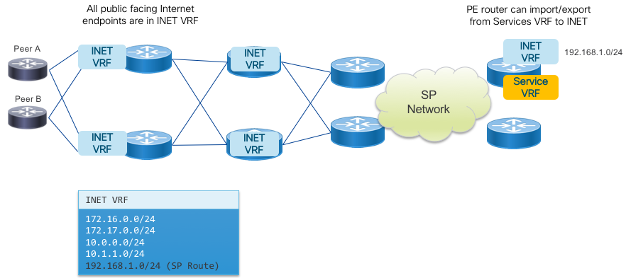
Internet in a VRF Only
In this method all Internet endpoints are configured in the same “Internet” VRF. The security benefit is removing dataplane connectivity between the global Internet and your underlying infrastructure, which is using the default VRF for all internal connectivity. This method uses the VPNv4/VPNv6 address families on all BGP peers and requires the Internet VRF be configured on all peering fabric nodes as well as SP PEs participating in the global routing table. If there are VPN customers or public-facing services in their own VRF needing Internet access, routes can be imported/exported from the Internet VRF on the PE devices they attach to.
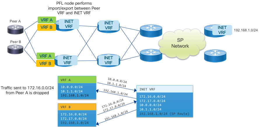
VRF per Peer, Internet in a VRF
This method combines the properties and configuration of the previous two methods for a solution with dataplane isolation per peer and separation of all public Internet traffic from the SP infrastructure layer. The exchange of routes between the peer VRFs and Internet VRF takes place on the PFL nodes with the rest of the network operating the same as the Internet in a VRF use case.
The VPNv4 and VPNv6 address families must be configured across all routers in the network.
Infrastructure ACLs
Infrastructure ACLs and their associated ACEs (Access Control Entries) are the perimeter protection for a network. The recommended PFL device configuration uses IPv4 and IPv6 infrastructure ACLs on all edge interfaces. These ACLs are specific to each provider’s security needs, but should include the following sections.
- Filter IPv4 and IPv6 BOGON space ingress and egress
- Drop ingress packets with a source address matching your own aggregate IPv4/IPv6 prefixes.
- Rate-limit ingress traffic to Unix services typically used in DDoS attacks, such as chargen (TCP/19).
- On ingress and egress, allow specific ICMP types and rate-limit to appropriate values, filter out ones not needed on your network. ICMP ttl-exceeded, host unreachable, port unreachable, echo-reply, echo-request, and fragmentation needed should always be allowed in some capacity.
BCP Implementation
Best Current Practices are informational documents published by the IETF to give guidelines on operational practices. This document will not outline the contents of the recommended BCPs, but two in particular are of interest to Internet peering. BCP38 explains the need to filter unused address space at the edges of the network, minimizing the chances of spoofed traffic from DDoS sources reaching their intended target. BCP38 is applicable for ingress traffic and especially egress traffic, as it stops spoofed traffic before it reaches outside your network. BCP194, BGP Operations and Security, covers a number of BGP operational practices, many of which are used in Internet peering. IOS-XR supports all of the mechanisms recommended in BCP38, BCP84, and BCP194, including software features such as GTTL, BGP dampening, and prefix limits.
BGP Attribute and CoS Scrubbing
Scrubbing of data on ingress and egress of your network is an important security measure. Scrubbing falls into two categories, control-plane and dataplane. The control-plane for Internet peering is BGP and there are a few BGP transitive attributes one should take care to normalize. Your internal BGP communities should be deleted from outbound BGP NLRI via egress policy. Most often you are setting communities on inbound prefixes, make sure you are replacing existing communities from the peer and not adding communities. Unless you have an agreement with the peer, normalize the MED attribute to zero or another standard value on all inbound prefixes.
In the dataplane, it’s important to treat the peering edge as untrusted and clear any CoS markings on inbound packets, assuming a prior agreement hasn’t been reached with the peer to carry them across the network boundary. It’s an overlooked aspect which could lead to peer traffic being prioritized on your network, leading to unexpected network behavior. An example PFL infrastructure ACL is given resetting incoming IPv4/IPv6 DSCP values to 0.
Per-Peer Control Plane Policers
BGP protocol packets are handled at the RP level, meaning each packet is handled by the router CPU with limited bandwidth and processing resources. In the case of a malicious or misconfigured peer this could exhaust the processing power of the CPU impacting other important tasks. IOS-XR enforces protocol policers and BGP peer policers by default.
BGP Prefix Security
RPKI Origin Validation
Prefix hijacking has been prevalent throughout the last decade as the Internet became more integrated into our lives. This led to the creation of RPKI origin validation, a mechanism to validate a prefix was being originated by its rightful owner by checking the originating ASN vs. a secure database. IOS-XR fully supports RPKI for origin validation.
BGPSEC (Reference Only)
RPKI origin validation works to validate the source of a prefix, but does not validate the entire path of the prefix. Origin validation also does not use cryptographic signatures to ensure the originator is who they say they are, so spoofing the ASN as well does not stop someone form hijacking a prefix. BGPSEC is an evolution where a BGP prefix is cryptographically signed with the key of its valid originator, and each BGP router receiving the path checks to ensure the prefix originated from the valid owner. BGPSEC standards are being worked on in the SIDR working group. Cisco continues to monitor the standards related to BGPSEC and similar technologies to determine which to implement to best serve our customers.
Appendix
Applicable YANG Models
| Model | Data |
|---|---|
|
openconfig-interfaces Cisco-IOS-XR-infra-statsd-oper Cisco-IOS-XR-pfi-im-cmd-oper |
Interface config and state Common counters found in SNMP IF-MIB |
|
openconfig-if-ethernet Cisco-IOS-XR-drivers-media-eth-oper |
Ethernet layer config and state XR native transceiver monitoring |
| openconfig-platform | Inventory, transceiver monitoring |
|
openconfig-bgp Cisco-IOS-XR-ipv4-bgp-oper Cisco-IOS-XR-ipv6-bgp-oper |
BGP config and state Includes neighbor session state, message counts, etc. |
|
openconfig-bgp-rib Cisco-IOS-XR-ip-rib-ipv4-oper Cisco-IOS-XR-ip-rib-ipv6-oper |
BGP RIB information. Note: Cisco native includes all protocols |
| openconfig-routing-policy | Configure routing policy elements and combined policy |
| openconfig-telemetry | Configure telemetry sensors and destinations |
|
Cisco-IOS-XR-ip-bfd-cfg Cisco-IOS-XR-ip-bfd-oper |
BFD config and state |
|
Cisco-IOS-XR-ethernet-lldp-cfg Cisco-IOS-XR-ethernet-lldp-oper |
LLDP config and state |
| openconfig-mpls | MPLS config and state, including Segment Routing |
|
Cisco-IOS-XR-clns-isis-cfg Cisco-IOS-XR-clns-isis-oper |
IS-IS config and state |
| Cisco-IOS-XR-fretta-bcm-dpa-hw-resources-oper | NCS 5500 HW resources |
NETCONF YANG Paths
Note that while paths are given to retrieve data from a specific leaf node, it is sometimes more efficient to retrieve all the data under a specific heading and let a management station filter unwanted data than perform operations on the router. Additionally, Model Driven Telemetry may not work at a leaf level, requiring retrieval of an entire subset of data.
The data is also available via NETCONF, which does allow subtree filters and retrieval of specific data. However, this is a more resource intensive operation on the router.
Metric Data
| Logical Interface Admin State | Enum |
| SNMP OID | IF-MIB:ifAdminStatus |
| OC YANG | openconfig-interfaces:interfaces/interface/state/admin-status (see OC model, not just up/down) |
| Native YANG | Cisco-IOS-XR-pfi-im-cmd-oper:interfaces/interface-xr/interface/state |
| Logical Interface Operational State | Enum |
| SNMP OID | IF-MIB:ifOperStatus |
| OC YANG | openconfig-interfaces:interfaces/interface/state/oper-status (see OC model, not just up/down) |
| Native YANG | Cisco-IOS-XR-pfi-im-cmd-oper:interfaces/interface-xr/interface/state |
| Logical Last State Change (seconds) | Counter |
| SNMP OID | IF-MIB:ifLastChange |
| OC YANG | openconfig-interfaces:interfaces/interface/state/last-change |
| Native YANG | Cisco-IOS-XR-pfi-im-cmd-oper:interfaces/interface-xr/interface/last-state-transition-time |
| Logical Interface SNMP ifIndex | Integer |
| SNMP OID | IF-MIB:ifIndex |
| OC YANG | openconfig-interfaces:interfaces/interface/state/if-index |
| Native YANG | Cisco-IOS-XR-snmp-agent-oper:snmp/interface-indexes/if-index |
| Logical Interface RX Bytes 64-bit | Counter |
| SNMP OID | IF-MIB:ifHCInOctets |
| OC YANG | openconfig-interfaces:/interfaces/interface/state/counters/in-octets |
| Native YANG | Cisco-IOS-XR-infra-statsd-oper:infra-statistics/interfaces/interface/latest/generic-counters/bytes-received |
| Logical Interface TX Bytes 64-bit | Counter |
| SNMP OID | IF-MIB:ifHCOutOctets |
| OC YANG | openconfig-interfaces:/interfaces/interface/state/counters/out-octets |
| Native YANG | Cisco-IOS-XR-infra-statsd-oper:infra-statistics/interfaces/interface/latest/generic-counters/bytes-sent |
| Logical Interface RX Errors | Counter |
| SNMP OID | IF-MIB:ifInErrors |
| OC YANG | openconfig-interfaces:/interfaces/interface/state/counters/in-errors |
| Native YANG | Cisco-IOS-XR-infra-statsd-oper:infra-statistics/interfaces/interface/latest/generic-counters/input-errors |
| MDT | Native |
| Logical Interface TX Errors | Counter |
| SNMP OID | IF-MIB:ifOutErrors |
| OC YANG | openconfig-interfaces:/interfaces/interface/state/counters/out-errors |
| Native YANG | Cisco-IOS-XR-infra-statsd-oper:infra-statistics/interfaces/interface/latest/generic-counters/output-errors |
| Logical Interface Unicast Packets RX | Counter |
| SNMP OID | IF-MIB:ifHCInUcastPkts |
| OC YANG | openconfig-interfaces:/interfaces/interface/state/counters/in-unicast-pkts |
| Native YANG | Not explicitly supported, subtract multicast/broadcast from total |
| Logical Interface Unicast Packets TX | Counter |
| SNMP OID | IF-MIB:ifHCOutUcastPkts |
| OC YANG | openconfig-interfaces:/interfaces/interface/state/counters/out-unicast-pkts |
| Native YANG | Not explicitly supported, subtract multicast/broadcast from total |
| Logical Interface Input Drops | Counter |
| SNMP OID | IF-MIB:ifIntDiscards |
| OC YANG | openconfig-interfaces:/interfaces/interface/state/counters/in-discards |
| Native YANG | Cisco-IOS-XR-infra-statsd-oper:infra-statistics/interfaces/interface/latest/generic-counters/input-drops |
| Logical Interface Output Drops | Counter |
| SNMP OID | IF-MIB:ifOutDiscards |
| OC YANG | openconfig-interfaces:/interfaces/interface/state/counters/out-discards |
| Native YANG | Cisco-IOS-XR-infra-statsd-oper:infra-statistics/interfaces/interface/latest/generic-counters/output-drops |
| Ethernet Layer Stats – All Interfaces | Counters |
| SNMP OID | NA |
| OC YANG | openconfig-interfaces:interfaces/interface/oc-eth:ethernet/oc-eth:state |
| Native YANG | Cisco-IOS-XR-drivers-media-eth-oper/ethernet-interface/statistics |
| Ethernet PHY State – All Interfaces | Counters |
| SNMP OID | NA |
| OC YANG | oc-platform:components/component/oc-transceiver:transceiver |
| Native YANG | Cisco-IOS-XR-drivers-media-eth-oper/ethernet-interface/interfaces/interface/phy-info |
| Ethernet Input CRC Errors | Counter |
| SNMP OID | NA |
| OC YANG | openconfig-interfaces:interfaces/interface/oc-eth:ethernet/oc-eth:state/oc-eth:counters/oc-eth:in-crc-errors |
| Native YANG | Cisco-IOS-XR-drivers-media-eth-oper/ethernet-interface/statistics/statistic/dropped-packets-with-crc-align-errors |
The following transceiver paths retrieve the total power for the transceiver, there are specific per-lane power levels which can be retrieved from both native and OC models, please refer to the model YANG file for additional information.
| Ethernet Transceiver RX Power | Counter |
| SNMP OID | NA |
| OC YANG | oc-platform:components/component/oc-transceiver:transceiver/oc-transceiver:physical-channels/oc-transceiver:channel/oc-transceiver:state/oc-transceiver:input-power |
| Native YANG | Cisco-IOS-XR-drivers-media-eth-oper/ethernet-interface/interfaces/interface/phy-info/phy-details/transceiver-rx-power |
| Ethernet Transceiver TX Power | Counter |
| SNMP OID | NA |
| OC YANG | oc-platform:components/component/oc-transceiver:transceiver/oc-transceiver:physical-channels/oc-transceiver:channel/oc-transceiver:state/oc-transceiver:input-power |
| Native YANG | Cisco-IOS-XR-drivers-media-eth-oper/ethernet-interface/interfaces/interface/phy-info/phy-details/transceiver-tx-power |
BGP Operational State
Global BGP Protocol State
IOS-XR native models do not store route information in the BGP Oper model, they are stored in the IPv4/IPv6 RIB models. These models contain RIB information based on protocol, with a numeric identifier for each protocol with the BGP ProtoID being 5. The protoid must be specified or the YANG path will return data for all configured routing protocols.
| BGP Total Paths (all AFI/SAFI) | Counter |
| SNMP OID | NA |
| OC YANG | openconfig-bgp:bgp/global/state/total-paths |
| Native YANG | Cisco-IOS-XR-ip-rib-ipv4-oper/rib/rib-table-ids/rib-table-id/summary-protos/summary-proto/proto-route-count/num-active-paths |
| MDT | Native |
| BGP Total Prefixes (all AFI/SAFI) | Counter |
| SNMP OID | NA |
| OC YANG | openconfig-bgp:bgp/global/state/total-prefixes |
| Native YANG | Cisco-IOS-XR-ip-rib-ipv4-oper/rib/rib-table-ids/rib-table-id/summary-protos/summary-proto/proto-route-count/active-routes-count |
| MDT | Native |
BGP Neighbor State
Example Usage
Due the construction of the YANG model, the neighbor-address key must be included as a container in all OC BGP state RPCs. The following RPC gets the session state for all configured peers:
<rpc message-id="101" xmlns="urn:ietf:params:xml:ns:netconf:base:1.0">
  <get>
    <filter>
      <bgp xmlns="http://openconfig.net/yang/bgp">
        <neighbors>
          <neighbor>
            <neighbor-address/>
            <state>
              <session-state/>
            </state>
          </neighbor>
        </neighbors>
      </bgp>
    </filter>
  </get>
</rpc>

<nc:rpc-reply message-id="urn:uuid:24db986f-de34-4c97-9b2f-ac99ab2501e3" xmlns:nc="urn:ietf:params:xml:ns:netconf:base:1.0" xmlns="urn:ietf:params:xml:ns:netconf:base:1.0">
  <nc:data>
    <bgp xmlns="http://openconfig.net/yang/bgp">
      <neighbors>
        <neighbor>
          <neighbor-address>172.16.0.2</neighbor-address>
          <state>
            <session-state>IDLE</session-state>
          </state>
        </neighbor>
        <neighbor>
          <neighbor-address>192.168.2.51</neighbor-address>
          <state>
            <session-state>IDLE</session-state>
          </state>
        </neighbor>
      </neighbors>
    </bgp>
  </nc:data>
</nc:rpc-reply>
| Complete State for all BGP neighbors | Mixed |
| SNMP OID | NA |
| OC YANG | openconfig-bgp:bgp/neighbors/neighbor/state |
| Native YANG | Cisco-IOS-XR-ipv4-bgp-oper/bgp/instances/instance/instance-active/default-vrf/neighbors |
| Complete State for all BGP neighbors | Mixed |
| SNMP OID | NA |
| OC YANG | openconfig-bgp:bgp/neighbors/neighbor/state |
| Native YANG | Cisco-IOS-XR-ipv4-bgp-oper/bgp/instances/instance/instance-active/default-vrf/neighbors |
| Session State for all BGP neighbors | Enum |
| SNMP OID | NA |
| OC YANG | openconfig-bgp:bgp/neighbors/neighbor/state/session-state |
| Native YANG | Cisco-IOS-XR-ipv4-bgp-oper/bgp/instances/instance/instance-active/default-vrf/neighbors/neighbor/connection-state |
| Message counters for all BGP neighbors | Counter |
| SNMP OID | NA |
| OC YANG | openconfig-bgp:bgp/neighbors/neighbor/state/messages |
| Native YANG | Cisco-IOS-XR-ipv4-bgp-oper/bgp/instances/instance/instance-active/default-vrf/neighbors/neighbor/message-statistics |
| Current queue depth for all BGP neighbors | Counter |
| SNMP OID | NA |
| OC YANG | /openconfig-bgp:bgp/neighbors/neighbor/state/queues |
| Native YANG |
Cisco-IOS-XR-ipv4-bgp-oper/bgp/instances/instance/instance-active/default-vrf/sessions/session/messages-queued-out Cisco-IOS-XR-ipv4-bgp-oper/bgp/instances/instance/instance-active/default-vrf/sessions/session/messages-queued-in |
BGP RIB Data
RIB data is retrieved per AFI/SAFI. To retrieve IPv6 unicast routes using OC models, replace “ipv4-unicast” with “ipv6-unicast”
IOS-XR native models do not have a BGP specific RIB, only RIB data per-AFI/SAFI for all protocols. Retrieving RIB information from these paths will include this data.
While this data is available via both NETCONF and MDT, it is recommended to use BMP as the mechanism to retrieve RIB table data.
Example Usage
The following retrieves a list of best-path IPv4 prefixes without attributes from the loc-RIB:
<rpc message-id="101" xmlns="urn:ietf:params:xml:ns:netconf:base:1.0">
  <get>
    <filter>
      <bgp-rib xmlns="http://openconfig.net/yang/rib/bgp">
        <afi-safis>
          <afi-safi>
            <ipv4-unicast>
              <loc-rib>
                <routes>
                  <route>
                    <prefix/>
                    <best-path>true</best-path>
                  </route>
                </routes>
              </loc-rib>
            </ipv4-unicast>
          </afi-safi>
        </afi-safis>
      </bgp-rib>
    </filter>
  </get>
</rpc>
| IPv4 Local RIB – Prefix Count | Counter |
| OC YANG | openconfig-bgp-rib:bgp-rib/afi-safis/afi-safi/ipv4-unicast/loc-rib/num-routes |
| Native YANG |
| IPv4 Local RIB – IPv4 Prefixes w/o Attributes | List |
| OC YANG | openconfig-bgp-rib:bgp-rib/afi-safis/afi-safi/ipv4-unicast/loc-rib/routes/route/prefix |
| IPv4 Local RIB – IPv4 Prefixes w/Attributes | List |
| OC YANG | openconfig-bgp-rib:bgp-rib/afi-safis/afi-safi/ipv4-unicast/loc-rib/routes |
| Native YANG |
The following per-neighbor RIB paths can be qualified with a specific neighbor address to retrieve RIB data for a specific peer. Below is an example of a NETCONF RPC to retrieve the number of post-policy routes from the 192.168.2.51 peer and the returned output.
<rpc message-id="101" xmlns="urn:ietf:params:xml:ns:netconf:base:1.0">
  <get>
    <filter>
      <bgp-rib xmlns="http://openconfig.net/yang/rib/bgp">
        <afi-safis>
          <afi-safi>
            <ipv4-unicast>
              <neighbors>
                <neighbor>
                  <neighbor-address>192.168.2.51</neighbor-address>
                  <adj-rib-in-post>
                    <num-routes/>
                  </adj-rib-in-post>
                </neighbor>
              </neighbors>
            </ipv4-unicast>
          </afi-safi>
        </afi-safis>
      </bgp-rib>
    </filter>
  </get>
</rpc>

<nc:rpc-reply message-id="urn:uuid:7d9a0468-4d8d-4008-972b-8e703241a8e9" xmlns:nc="urn:ietf:params:xml:ns:netconf:base:1.0" xmlns="urn:ietf:params:xml:ns:netconf:base:1.0">
  <nc:data>
    <bgp-rib xmlns="http://openconfig.net/yang/rib/bgp">
      <afi-safis>
        <afi-safi>
          <afi-safi-name xmlns:idx="http://openconfig.net/yang/rib/bgp-types">idx:IPV4_UNICAST</afi-safi-name>
          <ipv4-unicast>
            <neighbors>
              <neighbor>
                <neighbor-address>192.168.2.51</neighbor-address>
                <adj-rib-in-post>
                  <num-routes>3</num-routes>
                </adj-rib-in-post>
              </neighbor>
            </neighbors>
          </ipv4-unicast>
        </afi-safi>
      </afi-safis>
    </bgp-rib>
  </nc:data>
</nc:rpc-reply>
| IPv4 Neighbor adj-rib-in pre-policy | List |
| OC YANG | openconfig-bgp-rib:bgp-rib/afi-safis/afi-safi/ipv4-unicast/neighbors/neighbor/adj-rib-in-re |
| IPv4 Neighbor adj-rib-in post-policy | List |
| OC YANG | openconfig-bgp-rib:bgp-rib/afi-safis/afi-safi/ipv4-unicast/neighbors/neighbor/adj-rib-in-post |
| IPv4 Neighbor adj-rib-out pre-policy | List |
| OC YANG | openconfig-bgp-rib:bgp-rib/afi-safis/afi-safi/ipv4-unicast/neighbors/neighbor/adj-rib-out-pre |
| IPv4 Neighbor adj-rib-out post-policy | List |
| OC YANG | openconfig-bgp-rib:bgp-rib/afi-safis/afi-safi/ipv4-unicast/neighbors/neighbor/adj-rib-out-pre |
BGP Flowspec
| BGP Flowspec Operational State | Counters |
| SNMP OID | NA |
| OC YANG | NA |
| Native YANG | Cisco-IOS-XR-flowspec-oper |
| MDT | Native |
| BGP Total Prefixes (all AFI/SAFI) | Counter |
| SNMP OID | NA |
| OC YANG | openconfig-bgp:bgp/global/state/total-prefixes |
| Native YANG | Cisco-IOS-XR-ip-rib-ipv4-oper/rib/rib-table-ids/rib-table-id/summary-protos/summary-proto/proto-route-count/active-routes-count |
| MDT | Native |
Device Resource YANG Paths
| Device Inventory | List |
| OC YANG | oc-platform:components |
| NCS5500 Dataplane Resources | List |
| OC YANG | NA |
| Native YANG | Cisco-IOS-XR-fretta-bcm-dpa-hw-resources-oper/dpa/stats/nodes/node/hw-resources-datas/hw-resources-data |
Validated Model-Driven Telemetry Sensor Paths
The following represents a list of validated sensor paths useful for monitoring the Peering Fabric and the data which can be gathered by configuring these sensor paths.
Device inventory and monitoring, not transceiver monitoring is covered under openconfig-platform
 openconfig-platform:components
 cisco-ios-xr-fretta-bcm-dpa-hw-resources-oper/dpa/stats/nodes/node/hw-resources-datas/hw-resources-data
 cisco-ios-xr-controller-optics-oper:optics-oper/optics-ports/optics-port/optics-info
 cisco-ios-xr-shellutil-oper:system-time/uptime
 cisco-ios-xr-wdsysmon-fd-oper:system-monitoring/cpu-utilization
LLDP Monitoring
Cisco-IOS-XR-ethernet-lldp-oper:lldp
Cisco-IOS-XR-ethernet-lldp-oper:lldp/nodes/node/neighbors
Interface statistics and state
openconfig-interfaces:interfaces
Cisco-IOS-XR-infra-statsd-oper:infra-statistics/interfaces/interface/latest/generic-counters
Cisco-IOS-XR-pfi-im-cmd-oper:interfaces/interface-xr/interface
Cisco-IOS-XR-pfi-im-cmd-oper:interfaces/interface-xr/interface/interface-statistics
Cisco-IOS-XR-pfi-im-cmd-oper:interfaces/interface-xr/interface/interface-statistics/basic-interface-stats
The following sub-paths can be used but it is recommended to use the base openconfig-interfaces model
openconfig-interfaces:interfaces/interface
openconfig-interfaces:interfaces/interface/state
openconfig-interfaces:interfaces/interface/state/counters
openconfig-interfaces:interfaces/interface/subinterfaces/subinterface/state/counters
Aggregate bundle information (use interface models for interface counters)
sensor-group openconfig-if-aggregate:aggregate
sensor-group openconfig-if-aggregate:aggregate/state
sensor-group openconfig-lacp:lacp
sensor-group Cisco-IOS-XR-bundlemgr-oper:bundles
sensor-group Cisco-IOS-XR-bundlemgr-oper:bundle-information/bfd-counters
BGP Peering information
sensor-path openconfig-bgp:bgp
sensor-path openconfig-bgp:bgp/neighbors
sensor-path Cisco-IOS-XR-ipv4-bgp-oper/bgp/instances/instance/instance-active/default-vrf/neighbors
sensor-path Cisco-IOS-XR-ipv4-bgp-oper:bgp/instances/instance/instance-active/default-vrf/process-info/vrf
sensor-path Cisco-IOS-XR-ipv4-bgp-oper:bgp/instances/instance/instance-active/default-vrf/neighbors/neighbor
sensor-path Cisco-IOS-XR-ipv4-bgp-oper:bgp/instances/instance/instance-active/default-vrf/process-info/global
sensor-path Cisco-IOS-XR-ipv4-bgp-oper:bgp/instances/instance/instance-active/default-vrf/process-info/performance-statistics
sensor-path Cisco-IOS-XR-ipv4-bgp-oper:bgp/instances/instance/instance-active/default-vrf/bmp
sensor-path Cisco-IOS-XR-ipv6-bgp-oper/bgp/instances/instance/instance-active/default-vrf/neighbors
sensor-path Cisco-IOS-XR-ipv6-bgp-oper:bgp/instances/instance/instance-active/default-vrf/process-info/vrf
sensor-path Cisco-IOS-XR-ipv6-bgp-oper:bgp/instances/instance/instance-active/default-vrf/neighbors/neighbor
sensor-path Cisco-IOS-XR-ipv6-bgp-oper:bgp/instances/instance/instance-active/default-vrf/process-info/global
sensor-path Cisco-IOS-XR-ipv6-bgp-oper:bgp/instances/instance/instance-active/default-vrf/bmp
sensor-path Cisco-IOS-XR-ipv6-bgp-oper:bgp/instances/instance/instance-active/default-vrf/process-info/performance-statistics
IS-IS IGP information
sensor-path Cisco-IOS-XR-clns-isis-oper:isis/instances/instance/neighbors
sensor-path Cisco-IOS-XR-clns-isis-oper:isis/instances/instance/levels/interfaces
sensor-path Cisco-IOS-XR-clns-isis-oper:isis/instances/instance/levels/adjacencies
It is not recommended to monitor complete RIB tables using MDT but can be used for troubleshooting
Cisco-IOS-XR-ip-rib-ipv4-oper:rib/rib-table-ids/rib-table-id/summary-protos/summary-proto/rtype-isis-l1
Cisco-IOS-XR-ip-rib-ipv4-oper:rib/rib-table-ids/rib-table-id/summary-protos/summary-proto/rtype-isis-l2
Cisco-IOS-XR-ip-rib-ipv4-oper:rib/rib-table-ids/rib-table-id/summary-protos/summary-proto/rtype-isis-sum
Cisco-IOS-XR-ip-rib-ipv4-oper:rib/rib-table-ids/rib-table-id/summary-protos/summary-proto/proto-route-count
Cisco-IOS-XR-ip-rib-ipv6-oper:rib/rib-table-ids/rib-table-id/summary-protos/summary-proto/rtype-isis-l1
Cisco-IOS-XR-ip-rib-ipv6-oper:rib/rib-table-ids/rib-table-id/summary-protos/summary-proto/rtype-isis-l2
Cisco-IOS-XR-ip-rib-ipv6-oper:rib/rib-table-ids/rib-table-id/summary-protos/summary-proto/rtype-isis-sum
Cisco-IOS-XR-ip-rib-ipv6-oper:rib/rib-table-ids/rib-table-id/summary-protos/summary-proto/proto-route-count
QoS and ACL monitoring
openconfig-acl:acl
Cisco-IOS-XR-qos-ma-oper:qos/nodes/node/policy-map/interface-table/interface/input/statistics/
Cisco-IOS-XR-qos-ma-oper:qos/nodes/node/policy-map/interface-table/interface/input/statistics/class-stats/general-stats
Cisco-IOS-XR-qos-ma-oper:qos/nodes/node/policy-map/interface-table/interface/input/statistics/class-stats/queue-stats-array
BGP RIB information
It is not recommended to monitor these paths using MDT with large tables
openconfig-rib-bgp:bgp-rib
Cisco-IOS-XR-ip-rib-ipv6-oper:rib/rib-table-ids/rib-table-id/summary-protos/summary-proto/rtype-bgp-ext
Cisco-IOS-XR-ip-rib-ipv6-oper:rib/rib-table-ids/rib-table-id/summary-protos/summary-proto/rtype-bgp-int
Cisco-IOS-XR-ip-rib-ipv4-oper:rib/rib-table-ids/rib-table-id/summary-protos/summary-proto/rtype-bgp-ext
Cisco-IOS-XR-ip-rib-ipv4-oper:rib/rib-table-ids/rib-table-id/summary-protos/summary-proto/rtype-bgp-int
Routing policy Information
Cisco-IOS-XR-policy-repository-oper:routing-policy/policies
Leave a Comment