
Modernizing IX Fabric Design Using Segment Routing and EVPN
Modern IX Fabric Design
Internet Exchange History
Initial Exchanges
The Internet was founded on a loosely coupled open inter-connectivity model. The ability for two networks to use a simple protocol to exchange IP routing data was essential in the growth of the initial research-focused Internet as well as what it has become today. As the Internet grew it made sense to create locations where multiple networks could connect to each other over a common multi-access network. The initial exchanges connected to NFSNet in the 1980s were located in San Francisco, New York, and Chicago, with an additional European exchange in Stockholm, Sweden. During these days the connectivity was between universities and other government research institutions, but that would soon change as commercial interest in the Internet grew.
Growth through Internet Privatization
In the early 1990s those running the Internet saw the first commercial companies join. The ANS Internet backbone was built by a consortium of commercial companies (PSI, MCI, and Merit) and those companies wanted to offer commercial services such as Email across the infrastructure and do other entities already connected to the Internet. One of the first commercial exchanges created was simply called the “Commercial Internet Exchange” or CIX, located in Reston, Virginia.
One issue encountered in the initial exchange which still happens today is disagreements in connectivity. The original ANS backbone network, the most widely used network for connecting to the Internet, refused to connect to the CIX. As the Internet transitioned to a commercial network as opposed to a research network, the role of ANS diminished as exchanges like CIX become more important.
Dawn of the NAP and Rapid IX Expansion
In the mid 1990s as the Internet became more of a privatized public network, the need arose to create a number of public Internet peering exchange locations to help universities, enterprises, and service providers connect to each other. The original NAPs in the United States were run by either regional or national telecommunications companies. Figure 1 and the table below lists the original five US NAP locations. There were other exchange locations other than the NAPs, but these were the main peering points in the US, and at one point 90% of the worldwide Internet traffic flowed through these five locations.
| NAP Name | Location | Operator |
|---|---|---|
| AADS | Chicago, IL | Ameritech |
| MAE-EAST | Washington DC, DC | MFN, Pre-Existing Consortium |
| NYIX | New York, NY | Sprint |
| *MAE-WEST | San Jose, CA | MCI |
| PAIX | Palo Alto, CA | PacBell |
MAE-WEST was not one of the original four NAPs awarded by NFSNET but was already established as a west coast IX prior to 1993 when those NAPs were awarded.
The United States was not the only location in the world seeing the formation of Internet exchanges. The Amsterdam Internet Exchange, AMS-IX was formed in 1994 and is still the largest Internet Exchange in Europe.
IX Design Evolution
As the Internet has evolved so has IX design, driven by bandwidth growth and the need for more flexible interconnection as the scope of traffic and who connects to the Internet evolves.
Initial Exchange Design
The initial Internet exchanges were built to be multi-access networks where a participant could use a single physical connection for both private point to point and public connections. These exchanges primarily used either IP over FDDI or IP over ATM (over TDM) as the transport between peers. Some more forward-looking exchanges also used switched Ethernet, but it was not widely deployed in the mid-1990s. FDDI and ATM allowed the use of virtual circuits to provide point to point and multipoint connections over a common fabric. One important aspect of the fabrics is they used variable length data-link encoding, enabling packet-level statistical multiplexing. A fabric could be built using much less overall capacity than one using traditional TDM circuit switching. Interest in FDDI quickly waned and some IXs like MAE-EAST created a second fabric using ATM due to its popularity in the late 1990s and early 2000s.
Ethernet Takes Over
In the late 1990s Ethernet was becoming popular to build Local Area Networks due to its simplicity and cost. The use of VLANs to segment Ethernet traffic into a number of virtual networks also gave it the same flexibility of ATM and FDDI. The original NAPs began to transition to Ethernet at this point for intra-exchange connectivity, such as the case when two providers have equipment co-located at the same IXP facility. One hurdle however was Ethernet circuits for WAN connectivity had not become popular yet, so it took some time for Ethernet to overtake ATM and FDDI completely.
After Ethernet took over as the main transport for IX fabrics, they were primarily built using simple L2 switch fabrics. These switch fabrics do not have the loop prevention of IP networks, so protocols like STP or MST must be used for loop prevention. Ethernet fabrics are still in widespread use with IX networks, especially those with smaller scale requirements.
More Advanced Fabric Transport
As IX fabrics began to grow, there arose a need for better control of traffic paths and more capabilities than what simple L2 fabrics could offer. This is not an exhaustive list of potential transport options, but lists a few popular ones for IX use.
VPLS and P2P PW over MPLS
MPLS (Multi-Protocol Label Switching) has been a popular data plane shim layer for providing virtual private networks over a common fabric for more than a decade now. Distribution of labels is done using LDP or RSVP-TE. RSVP-TE offer resilience through the use of fast-reroute and the ability to engineer traffic paths based on constraints. In the design section we will examine the benefits of Segment Routing over both LDP and RSVP-TE.
MPLS itself is not enough to interconnect IX participants, it requires using overlay VPN services. VPLS (Virtual Private Lan Service) is the service most widely deployed today, emulating the data plane of a L2 switch, but carrying the traffic as MPLS-encapsulated frames. Point to point services are commonly provisioned using point to point pseudowires signaled using either a BGP or LDP control-plane. Please see RFC 4761 and RFC 6624.
EVPN over VXLAN
We will speak more about EVPN in the design section, but it has become the modern way to deliver L2VPN services, using a control-plane similar to L3VPN. EVPN extends MP-BGP with signaling extensions for L2 and L3 services that can utilize different underlying transport methods. VXLAN is one method which encapsulates Layer2 frames into a VXLAN packet carried over IP/UDP. VXLAN is considered “overlay transport” since it is carried in IP over any underlying path. VXLAN has no inherent ability to provide resiliency or traffic engineering capabilities. Gaining that functionality requires layering VXLAN on top of MPLS transport, adding complexity to the overall network. Using simple IP/UDP encapsulation, VXLAN is well suited for overlays traversing 3rd party opaque L3 networks, but IXP networks do not generally have this requirement.
TRILL, PBB, and other L2 Fabric Technology
At a point in the early 2010s there was industry momentum towards creating a more advanced network without introducing L3 routing into the network, considered complex by those in favor of L2. Two protocols with support were TRILL (Transparent Interconnection of Lots of Links), 802.1ah PBB (Provider Backbone Bridging), and its TE addition PBB-TE. Proprietary fabrics were also proposed like Cisco FabricPath and Juniper QFabric. Ultimately these technologies faded and did not see widespread industry adoption.
Modern IX Fabric Requirements
Hardware
The heart of an IX is the connectivity to participants at the edge and the transport connecting them to other participants. There are several components that needs to be considered when looking at hardware to build a modern IX.
High-Density and Future-Proof
Bandwidth growth today requires the proper density to support the needs of the specific provider within a specific facility. This can range from 10s of Gbps to 10s of Tbps, requiring the ability to support a variable number of 10G and 100G interfaces. The ability to expand without replacing a chassis is also important as it can be especially cumbersome to do so in non-provider facilities. Today’s chassis-based deployments must be able to support a 400G future.
Edge and WAN Interface Flexibility
Ethernet is the single type of connectivity used today for connecting to an IX, but an IX does need flexibility to peers and the connectivity between IX fabric elements. 10G connections have largely replaced 1G connections for peers due to cost reduction in both device ports and optics. However, there is still a need for 1G connectivity as well as different physical medium types such as 10GBaseT. In order to support connectivity such as dark fiber, IXs sometimes must also provide ZR, ER, or DWDM based Ethernet port types.
Modern IXs are also not typically limited ot a single physical location, so WAN connectivity also becomes important. Using technologies like coherent CFP2-DCO may be a requirement to interconnect IX facilities via high-speed flexible links.
Power and Space
It almost goes without saying devices in a IX location must have the lowest possible space, power, and cooling footprint per BPS of traffic delivered. As interconnection continues to grow technology must advance to support higher density devices without considerably higher power and cooling requirements.
Packet Transport Requirements
Resiliency is key within any fabric, and the IX fabric must be able to withstand the failure of a link or node with minimal traffic disruption. Boundaries between different IX facilities must be redundantly connected.
Service Types and Requirements
In a modern IX there can be both traditional L2 connectivity as well as L3 connectivity. The following outlines the different service types and their requirements. One common requirement across all service types is redundant attachment. Each service type should support either active/active or active/standby connectivity from the participant.
Point to Point Connectivity
The most basic service type an IX fabric must provide is point to point participant connectivity. The edge must be able to accept and map traffic to a specific service based on physical port or VLAN tagged frames. The ability to rewrite VLANs at the edge may also be a requirement.
Multi-point Connectivity (Multi-lateral Peering)
Multi-point connectivity is most commonly used for multi-lateral peering fabrics or “public” fabrics where all participants belong to the same bridge domain. This type of fabric requires less configuration since a single IP interface is used to connect to multiple peers. BGP configuration can also be greatly simplified if the IX provides a route-server to advertise routes to participant peers versus a full mesh of peering sessions.
Layer 3 Cloud or Transit Connectivity
Depending on the IX provider, they may offer their own blended transit services or multi-cloud connections via L3 connectivity. In this service type the IX will peer directly with the participant or provide a L3 gateway if the participant is not using dynamic routing to the IX.
QoS Requirements
Quality of Service or Class of Service (CoS) covers an array of traffic handling components. With the use of higher speed 10G and 100G interfaces as defacto physical connectivity, the most basic QoS needed is policing or shaping of ingress traffic at the edge to the contracted rate of the participant.
An IX can also offer differentiated services for connectivity between participants requiring traffic marking at the edge and specific treatment across the core of the network.
Broadcast, Unknown Unicast, and Multicast Traffic
A L2 fabric, whether traditional L2 switching or emulated via a technology like EVPN must provide controls to limit the effects of BUM traffic having the potential to flood networks with unwanted or duplicate traffic. At the PE-CE boundary “storm” controls must be supported to limit these traffic types to sensible packet rates.
Security
Peer Connection Isolation
One of the key tenets of a multi-tenant network fabric is to provide secure traffic isolation between parties using the fabric. This can be done using “soft” or “hard” mechanisms. Soft isolation uses packet structure in order to isolate traffic between tenants, such as MPLS headers or specific service tags. As you move down the stack, the isolation becomes “harder”, first using VLAN tags, channels in the case of Flex Ethernet, or separate physical medium to completely isolate tenants. Harder isolation is typically less efficient and more difficult to operate. In modern networks, isolation using VPN services is regarded as sufficient for an IX fabric and offers the greatest flexibility and scale. The isolation must be performed on the IX fabric itself and protect against users spoofing MPLS headers or VLANs tags at the attachment point in the network.
L2 Security
The table below lists the more common L2 security features required by an IX network. Some of these should perform the action of disabling either permanently or temporarily a connected port.
| Feature | Description |
|---|---|
| L2 ACL | Ability to create filters based on L2 frame criteria (SRC/DST MAC, Ethertype, control BPDUs, etc) |
| ARP/ND/RA policing | Police ARP/ND/RA requests |
| MAC scale limits | Limit MAC scale for specific Bridge Domain |
| Static ARP | Override dynamic ARP with static ARP entries |
L3 Security
| Feature | Description |
|---|---|
| L3 ACL | Ability filter on L3 criteria, useful for filtering attacks towards fabric subnets and participants |
| ARP/ND/RA policing | Police ARP/ND/RA requests |
| MAC scale limits | Limit MAC scale for specific Bridge Domain |
| Static ARP | Override dynamic ARP with static ARP entries |
Additional IX Components
Fabric and Peer Service Automation
Ideally the management of the underlying network fabric, participant interfaces, and participant services are automated. Using a tool like Cisco NSO as a single source of truth for the network eliminates configuration errors, eases deployment, and eases the removal of configuration when it is no longer needed. NSO also allows easy abstraction and deployment of point to point and multi-point services through the use of defined service models and templates. Deployed services should be well-defined to reduce support complexity.
Route Servers
A redundant set of route servers is used in many IX deployments to eliminate each peer having to configure a BGP session to every other peer. The route server is similar to a BGP route reflector with the main difference being a route server operates with EBGP peers and not IBGP peers. The route server also acts as a point of route security since the filters governing advertisements between participants is typically performed on the route server. Route server definition can be found in RFC 7947 and route server operations in RFC 7948.
Route Looking Glass
Looking glasses allow an outside user or internal participant to view the current real-time routing for a specific prefix or set of prefixes. This is invaluable for troubleshooting routing issues.
Analytics and Monitoring
Fabric Telemetry
Having accurate statistics on peer and fabric state is important for evaluating the current health of the fabric as well assist in capacity planning. Monitoring traffic utilization, device health, and protocol state using modern telemetry such as streaming telemetry can help rectify faults faster and improve reliability. See the automation section of the design for a list of common Cisco and OpenConfig models used with streaming telemetry.
Route Update History
Route update history is one area of IX operation that can assist not only with IX growth but also Internet health as a whole. Being able to trace the history of route updates coming through an IX helps both providers and enterprises determine root cause for traffic issues, identify the origin of Internet security events, and assist those researching Internet routing change over time. Route update history can be communicated by either BGP or using BGP Monitoring Protocol (BMP).
Modern IXP Fabric Network Design
Topology Considerations
Scale Out Design
We can learn from modern datacenter design in how we build a modern IX fabric, at least the network located within a single facility or group of locations in close proximity. The use of smaller functional building blocks increases operational efficiency and resiliency within the fabric. Connecting devices in a Clos (leaf/spine or fat-tree are other names) fabric seen in Figure XX versus a large modular chassis approach has a number of benefits.
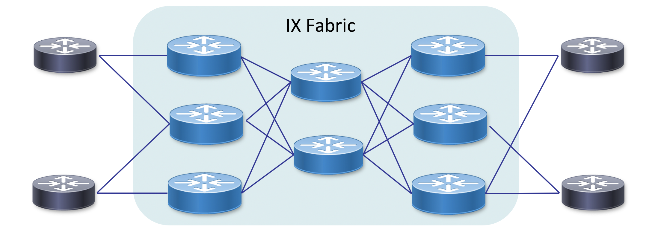
Fabric Design Benefits
- Scale the fabric by simply adding devices and interconnects
- Optimal connectivity between fabric endpoints
- Increased resiliency by utilizing ECMP across the fabric
- Ability to easily takes nodes in and out of service without affecting many services
- In the case of interconnecting remote datacenters using a more fabric based approach increases overall scale and resiliency.
Segment Routing Underlay
Segment Routing and Segment Routing Traffic Engineering
Segment Routing is the modern simplified packet transport control-plane for multi-service networks. Segment Routing eliminates separate IGP and label distribution protocols running in parallel while providing built-in resilience and traffic engineering capabilities. Much more information on segment routing can be located at http://www.segment-routing.net
SR-MPLS Data Plane
One important point with Segment Routing is that it is data plane agnostic, meaning the architecture is built to support multiple data plane types. The SR “SID” is an identifier expressed by the underlying data plane. The Segment Routing MPLS data plane uses standard MPLS headers to carry traffic end to end, with SR responsible for label distribution and path computation. In this design we will utilize the SR MPLS data plane, but as other data planes such as Segment Routing IPv6 become mature they could plugin in as well.
Segment-Routing Flexible Algorithms
An exciting develop in SR capabilities is through the use of “Flexible Algorithms.” Simply put Flex-Algo allows one to define multiple SIDs on a single device with each one representing a specific “algorithm.” Using the algorithm as a constraint in head-end path computation simplifies the path to a single label since the algorithm itself takes of pruning links not applicable to the topology. See the figure below for an example of Flex-Algo using the initial topology definition to restrict the path to only encrypted links.
Constraint-based SR Policies
Path computation on the head-end SR node or external PCE can include more advanced constraints such as latency, link affinity, hop count, or SRLG avoidance. Cisco supports a wide range of path constraints both within XR on the SR head-end node as well as through SR-PCE, Cisco’s external Path Computation Element for Segment Routing.
On-Demand SR Policies
Cisco has simplifies the control-plane even more with a feature called ODN (On Demand Next Hop) for SR-TE. When a head-end node receives an EVPN BGP route with a specific extended community, known as the color community, it instructs the head-end node to create an SR Policy to the BGP next-hop following the defined constraints for that community. The head-end node can compute the SR Policy path itself, or the ODN policy can instruct the head-end to consult a PCE for end-to-end path computation.
Segment Routing Benefits in IXP Use
- Reduction of control-plane protocols across the fabric by eliminating additional label distribution protocols
- Advanced traffic engineering capabilities, all while reducing overall network complexity
- Built-in local protection through the use of TI-LFA, computing the post-convergence path for both link and node protection
- Advanced OAM capabilities using real-time performance measurement and automated data-plane path monitoring
- Ability to tie services to defined underlay paths, unlike pure overlays like VXLAN
- Quickly add to the topology by simply turning up new IGP links
L2 IX Services using Segment Routing and EVPN
EVPN Background
EVPN is the next-generation service type for creating L2 VPN overlay services across a Segment Routing underlay network. EVPN replaces services like VPLS emulating a physical Ethernet switch with a scalable BGP based control-plane. MAC addresses are no longer learned across the network as part of traffic forwarded, they are learned at the edges and distributes as BGP VPN routes. Below is a list of just a few of the advantages of EVPN over legacy services types such as VPLS or LDP-signaled P2P pseudowires.
- RFC 7432 is the initial RFC defining EVPN service types and operation covering both MP and P2P L2 services
- VPWS point to point Ethernet VPN
- ELAN multi-point Ethernet VPN
- EVPN brings the paradigms of BGP L3VPN to Ethernet VPNs
- MAC and ARP/ND (MAC+IP) information is advertised using BGP NLRI
- EVPN signaling identifies the same ESI (Ethernet Segment) connected to multiple PE nodes, allowing active/active or active/standby multi-homing
- EVPN has been extended to support IRB (Integrated Routing and Bridging) for inter-subnet routing
EVPN Benefits for IX Use
- BGP-based control plane has obvious scaling and distribution benefits
- Eliminates mesh of pseudowires between L2 endpoints
- All-active per-flow load-balancing across redundant active links between IX and peers
- Reduced flooding scope for ARP traffic
- BUM labels act as a way to control flooding without complex split-horizon configuration
- Fast MAC withdrawal improves convergence vs. data plane learning
- Filter ARP/MAC advertisements via common BGP route policy
- Distributed MAC pinning
- Once MAC is learned on a CE interface, it is advertised with EVPN BD as “sticky”
- Remote PEs will drop traffic sourced from a MAC labeled as sticky from another PE
- Works in redundancy scenarios
- Works seamlessly with existing L2 Ethernet fabrics without having to run L2 protocols such as STP within EVPN itself
- Provides L2 multi-homing replacement for MC-LAG and L3 multi-homing replacement for VRRP/HSRP
Modern IXP Deployment
Background
In the following section we will explore the deployment using IOS-XR devices and CLI. We will start with the most basic deployment and add additional components to enable features such as multi-plane design and L3 services.
Single-plane Segment Routing Underlay Deployment
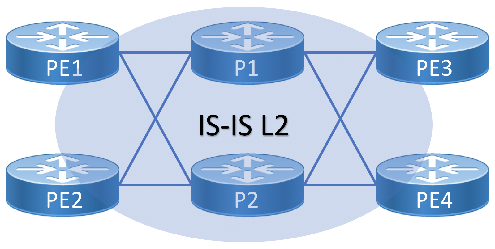
In the simplest deployment example, Segment Routing is deployed by configuring either OSPF or IS-IS with SR MPLS extensions enabled. The configuration example below utilizes IS-IS as the SR underlay IGP protocol. The underlay is deployed as a single IS-IS L2 domain using Segment Routing MPLS.
Topology Diagram for Single-plane Fabric
SRGB and SRLB Definition
It’s recommended to first configure the Segment Routing Global Block (SRGB) across all nodes needing connectivity between each other. In most instances a single SRGB will be used across the entire network. In a SR MPLS deployment the SRGB and SRLB correspond to the label blocks allocated to SR. IOS-XR has a maximum configurable SRGB limit of 512,000 labels, however please consult platform-specific documentation for maximum values. The SRLB corresponds to the labels allocated for SIDs local to the node, such as Adjacency-SIDs. It is recommended to configure the same SRLB block across all nodes. The SRLB must not overlap with the SRGB. The SRGB and SRLB are configured in IOS-XR with the following configuration:
segment-routing
segment-routing
 global-block 16000 16999
 local-block 17000 17999
Base IGP / Segment Routing Configuration
The following configuration example shows an example IS-IS deployment with SR-MPLS extensions enabled for the IPv4 address family. The SR-enabling configuration lines are bolded, showing how Segment Routing and TI-LFA (FRR) can be deployed with very little configuration. SR must be deployed on all interconnected nodes to provide end to end reachability. This example shows defining an absolute prefix-sid as well as a manually defined adjacency SID.
It is recommended to use absolute SIDs and manual adjacency SIDs if possible. Interoperability with other vendors requires the use of relative prefix-SIDs. A protected SID is eligible for backup path computation. In the case of having multiple adjacencies between the same two nodes, use the same adjacency-sid on each link.
router isis example
 set-overload-bit on-startup wait-for-bgp
 is-type level-2-only
 net 49.0002.1921.6801.4003.00
 distribute link-state
 log adjacency changes
 log pdu drops
 lsp-refresh-interval 65000
 max-lsp-lifetime 65535
 lsp-password keychain ISIS-KEY
 address-family ipv4 unicast
  maximum-paths 16
  metric-style wide
  mpls traffic-eng level-2-only
  mpls traffic-eng router-id Loopback0
  maximum-paths 32
  segment-routing mpls
 !
 interface Loopback0
  passive
  address-family ipv4 unicast
   metric 10
   prefix-sid absolute 16041
   !
  !
 !
 interface GigabitEthernet0/0/0/1
  circuit-type level-2-only
  point-to-point
  address-family ipv4 unicast
   fast-reroute per-prefix
   fast-reroute per-prefix ti-lfa
   metric 10
   adjacency-sid absolute 15002 protected
The two key elements to enable Segment Routing are segment-routing mpls under the ipv4 unicast address family and the node prefix-sid absolute 16041 definition under the Loopback0 interface. The prefix-sid can be defined as either an indexed value or absolute. The index value is added to the SRGB start (16000 in our case) to derive the SID value. Using absolute SIDs is recommended where possible, but in a multi-vendor network where one vendor may not be able to use the same SRGB as the other, using an indexed value is necessary.
Enabling TI-LFA
Topology-Independent Loop-Free Alternates is not enabled by default. The above configuration enables TI-LFA on the Gigabit0/0/0/1 interface for IPv4 prefixes. TI-LFA can be enabled for all interfaces by using this command under the address-family ipv4 unicast in the IS-IS instance configuration. It is recommended to enable it at the interface level to control other TI-LFA attributes such as node protection and SRLG support.
interface GigabitEthernet0/0/0/1
  circuit-type level-1
  point-to-point
  address-family ipv4 unicast
   fast-reroute per-prefix
   fast-reroute per-prefix ti-lfa
  metric 10
This is all that is needed to enable Segment Routing, and you can already see the simplicity in its deployment vs additional label distribution protocols like LDP and RSVP-TE
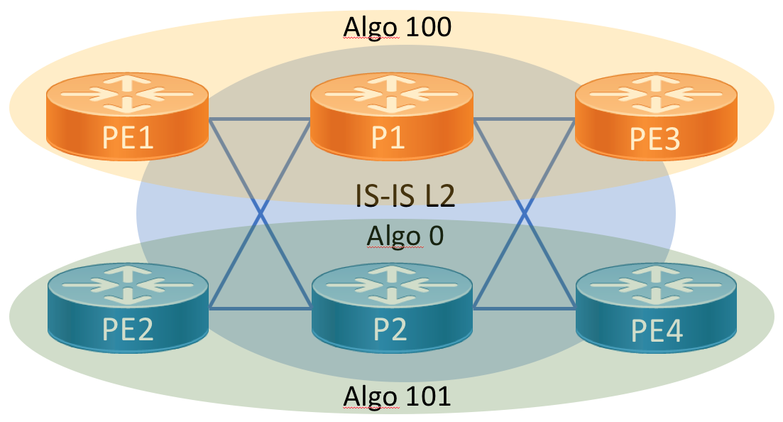
Dual-Plane Fabric using SR Flexible Algorithms
The dual plane design extends the base configuration by defining a topology based on SR flexible algorithms. Defining two independent topologies allows us to easily support disjoint services across the IX fabric. IX operators can offer diverse services without the fear of convergence on common links. This can be done with a minimal amount of configuration. Flex-algo also supports LFA and will ensure LFA paths are also constrainted to a specific topology.
Flex-Algo Background
SR Flex-Algo is a simple extension to SR and its compatible IGP protocols to advertise membership in a logical network topology by configuring a specific “algorithm” attached to a node prefix-sid. All nodes with the same algorithm defined participate in the topology and can use the definition to define the behavior of a path. In the below example when a head-end computes a path to node 9’s node-SID assigned to algorithm 129 it will only use nodes participating in the minimal delay topology. This means a constraint can be met using a single node SID in the SID list instead of multiple explicit SIDs. Flex-algo is defined in IETF draft: draft-ietf-lsr-flex-algo and more details on Flex-Algo can be found on http://www.segment-routing.net
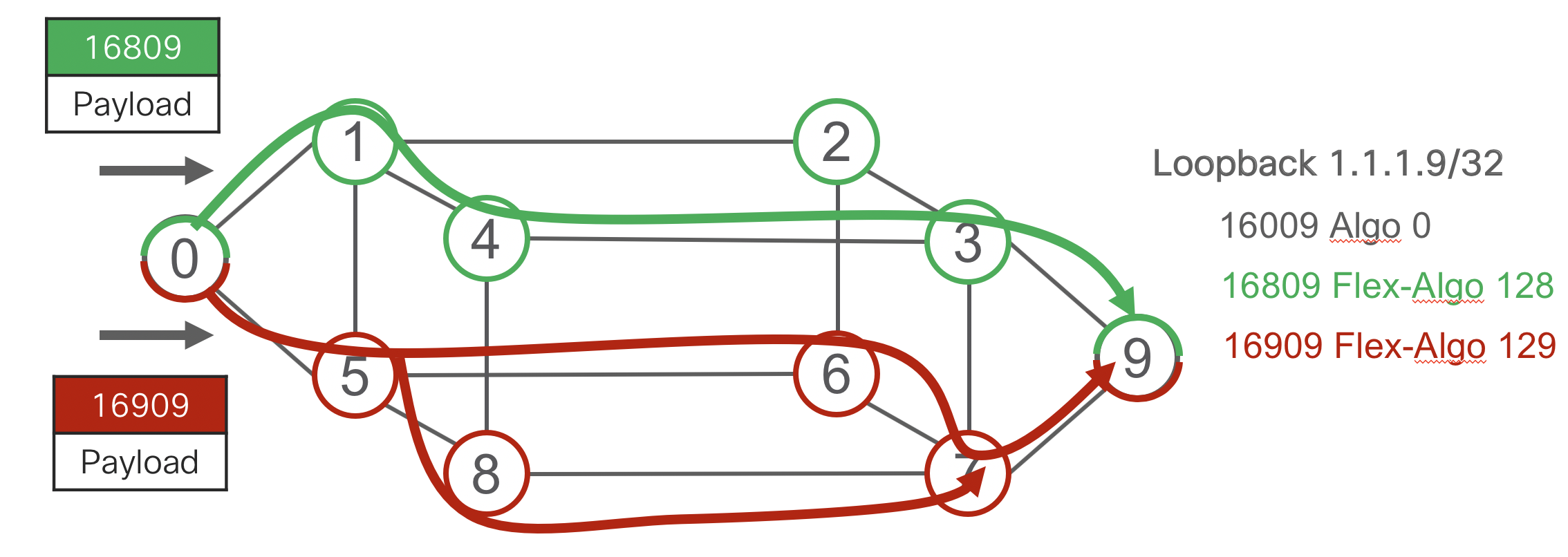
- Algo 0 = IGP Metric
- Algo 128 = Green = Minimize TE Metric
- Algo 129 = Red = Minimize Delay
Diagram
Dual-plane Flex-Algo Configuration
We will not re-introduce all of the configuration but the subset necessary to define both planes. To enable flexible algorithms you must first define the algorithms globally in IS-IS. The second step is to define a node prefix-sid on a Loopback interface and attach an algorithm to the SID. By default all nodes participate in algorithm 0, which is to simply compute a path based on minimal IGP metric.
The advertise-definition option advertises the definition through the IGP domain. Using this command the definition can be defined on a subset of nodes and the global configuration is unnecessary on all nodes. It’s recommended to define the flex-algo identifiers on all participating nodes and advertise them.
- IS-IS Configuration
interface GigabitEthernet0/0/0/1
router isis 1
 flex-algo 100
  advertise-definition
!
flex-algo 200
  advertise-definition
!
interface Loopback0
 address-family ipv4 unicast
  prefix-sid algorithm 100 absolute 16141
  prefix-sid algorithm 101 absolute 16241
Simple L2VPN Services using EVPN
We will first look at EVPN configuration for deploying basic point to point and multi-point L2 services without specific traffic engineering constraints or path diversity requirements. These services will simply follow the shortest path across the network.
BGP AFI/SAFI Configuration
EVPN uses additional BGP address families in order to carry EVPN information across the network. EVPN uses the BGP L2VPN AFI of 25 and a SAFI of 70. In order to carry EVPN information between two peers, this AFI/SAFI must be enabled on all peers. The following shows the minimum BGP configuration to enable this at a global and peer level.
router bgp 100
 bgp router-id 100.0.0.1
 address-family l2vpn evpn
 !
!
neighbor-group EVPN
 remote-as 100
 update-source Loopback0
 address-family l2vpn evpn
 !
!
neighbor 100.0.0.2
 use neighbor-group EVPN
At this point the two neighbors will become established over the EVPN AFI/SAFI. The command to view the relationship in IOS-XR is show bgp l2vpn evpn summary
EVPN Service Configuration Elements
EVI - Ethernet Virtual Instance
All EVPN services require the configuration of the Ethernet Virtual Instance identifier, used to advertise the existence of an EVPN service endpoint to routers participating in the EVPN service network. The EVI is locally significant to a PE but it’s recommended the same EVI be configured for all routers participating in a particular EVPN service.
RD - Route Distinguisher
Similar to L3VPN and BGP-AD L2VPN, a Route Distinguisher is used to differentiate EVPN routes belonging to different EVIs. The RD is auto-generated based on the Loopack0 IP address as specified in the EVPN RFC.
RT - Route Target
Also similar to L3VPN and BGP-AD L2VPN, a Route Target extended community is defined so EVPN routes are imported into the correct EVI across the network. The RT is auto-generated based on the EVI ID, but can be manually configured. It is recommended to utilize the auto-generated RT value.
ESI - Ethernet Segment Identifier
The ESI is used to identify a particular Ethernet “segment” for the purpose of multi-homing. In single-homed scenarios, the ESI is set to 0 by default. In multi-homing scenarios such all-active attachment, the ESI is configured the same on multiple routers. If it is known an attachment will never be multi-homed, using the default ESI of 0 is recommended, but if there is a chance it may be multi-homed in the future, using a unique ESI is recommended. The ESI is a 10-octet value with 1 byte used for the type and 9 octets for the value. Values of 0 and the maximum value are reserved.
Attachment Circuit ID
This value is used only with EVPN VPWS point to point services. It defines a local attachment circuit ID and the remote attachment circuit ID to be used in signalling the endpoints and for direct traffic to the correct attachment point. The local ID does not have to be the same on both ends, but it is recommended.
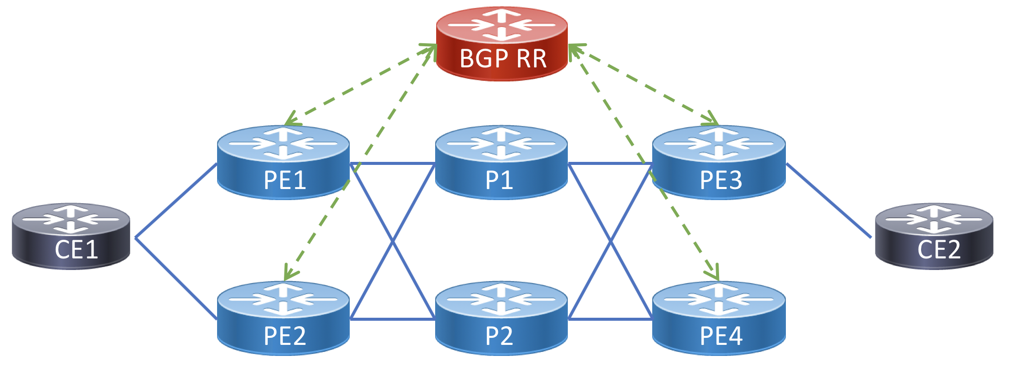
Topology Diagram for Example Services
The following is a topology diagram to follow along with the service endpoints in the below service configuration examples. Each CE node represents a peering fabric participant.
P2P Peer Interconnect using EVPN-VPWS
The following highlights a simple P2P transparent L2 interconnect using EVPN-VPWS. It is assumed the EVPN BGP address family has been configured.
Single-homed EVPN-VPWS service
The simplest P2P interconnect is single-homed on both ends. The single-active service can use an entire physical interface or VLAN tags to identify a specific service. This service originates on PE1 and terminates on PE3. The service data plane path utilizes ECMP across the core network, one of the benefits of using an SR underlay. As you can see in the config below, there is no static neighbor config, P2P VPWS connections are dynamically setup by matching the EVI, target, and source identifiers. The target and source identifiers must match on the two nodes participating in the service.
Diagram 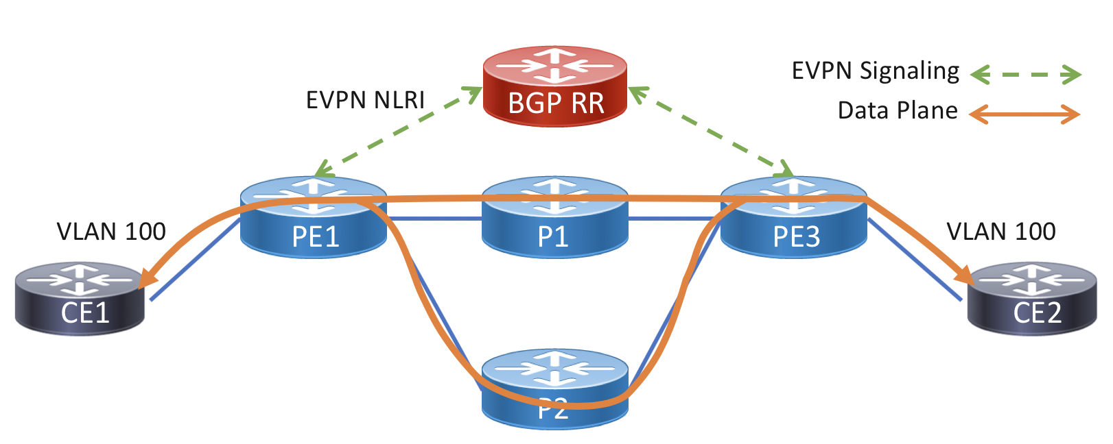
PE1
interface TenGigabitEthernet0/0/0/1.100 encapsulation l2transport
 encapsulation dot1q 100
 rewrite ingress tag pop 100 symmetric
 !
!
l2vpn
 xconnect group evpn-vpws-example
  p2p pe1-to-pe2
    interface TenGigabitEthernet0/0/0/1.100
    neighbor evpn evi 10 target 100 source 101
PE3
interface TenGigabitEthernet0/0/1/1.100 encapsulation l2transport
 encapsulation dot1q 100
 rewrite ingress tag pop 100 symmetric
 !
!
l2vpn
 xconnect group evpn-vpws-example
  p2p pe1-to-pe2
    interface TenGigabitEthernet0/0/1/1.100
    neighbor evpn evi 10 target 101 source 100
Multi-homed Single-active/All-active EVPN-VPWS service
A multi-homed service uses two attachment circuits from the CE to unique PE devices on the provider side. LACP is used between the PEs and CE device in single-active and all-active multi-homing. This requires configuring a static LACP ID and ESI on both PE routers. Multi-chassis LACP protocols such as ICCP are not required, all muti-homed signaling is done with the EVPN control-plane.
In this example CE1 is configured in a multi-homed all-active configuration to PE1 and PE2, CE2 continues to be configured as single-homed. In this configuration traffic will be hashed using header information across all active links in the bundle across all PEs. PE3 will receive two routes for the VPWS service and utilize both to balance traffic towards PE1 and PE2. Another option is to use single-active load-balancing mode, which will only forward traffic towards the ethernet-segment from the DF (default forwarder). Single-active is commonly used to enforce customer bandwidth rates, while still providing redundancy. In the case where there are multiple EVPN services on the same bundle interface, they will be balanced across the interfaces using the DF election algorithm.
Diagram 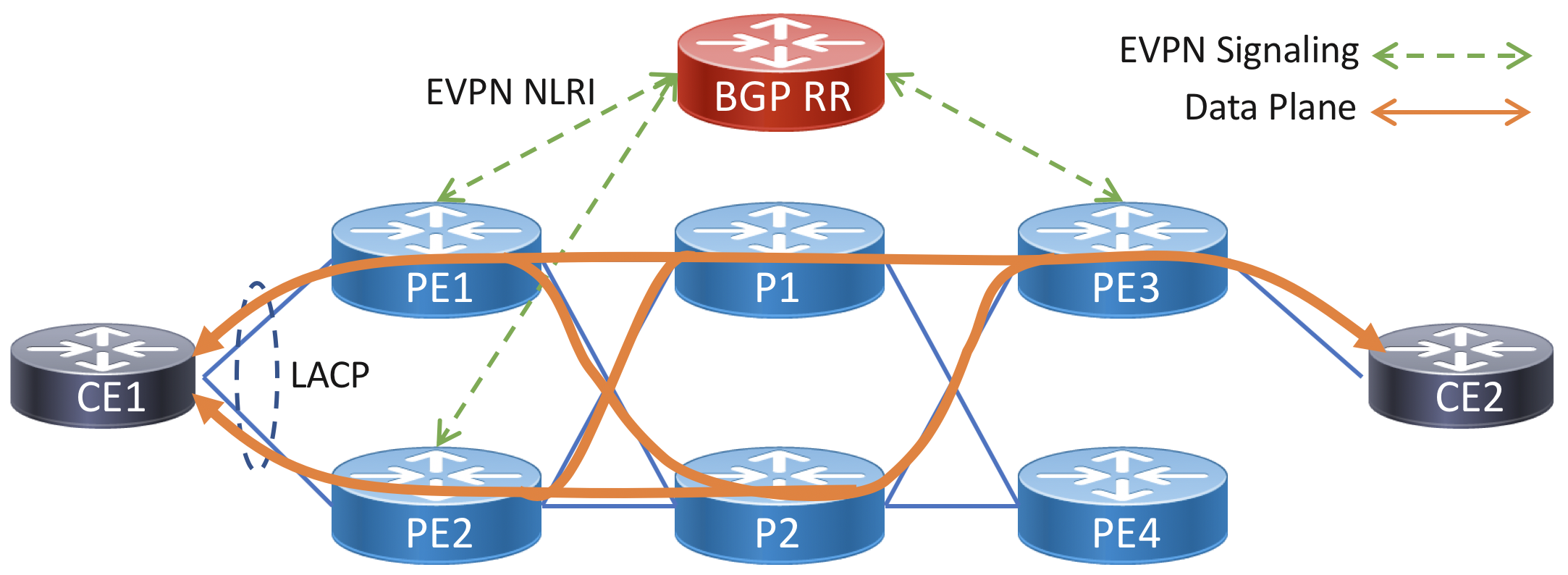
Note the LACP system MAC and ethernet-segment (ESI) on both PE nodes must be configured with the same values.
PE1
lacp system mac 1001.1001.1001
!
interface TenGigabitEthernet0/0/0/1
  description "To CE1"
  bundle id 1 mode on
  !
interface Bundle-Ether1.100 l2transport
 encapsulation dot1q 100
 rewrite ingress tag pop 100 symmetric
 !
!
!
evpn
 group 1
  core interface TenGigabitEthernet0/0/1/24
 !
 interface Bundle-Ether1.100
  ethernet-segment type 0 11.11.11.11.11.11.11.11.11
  load-balancing-mode single-active  <-- Optional
  core-isolation-group 1
!
!
l2vpn
 xconnect group evpn-vpws-example
  p2p pe1-to-pe2
    lacp system mac 3637.3637.3637
    neighbor evpn evi 10 target 100 source 100
PE2
lacp system mac 1001.1001.1001
!
interface TenGigabitEthernet0/0/0/1
  description "To CE1"
  bundle id 1 mode on
  !
interface Bundle-Ether1.100 l2transport
 encapsulation dot1q 100
 rewrite ingress tag pop 100 symmetric
 !
!
!
evpn
 group 1
  core interface TenGigabitEthernet0/0/1/24
 !
 interface Bundle-Ether1.100
  ethernet-segment type 0 11.11.11.11.11.11.11.11.11
  load-balancing-mode single-active  <-- Optional
  core-isolation-group 1
!
l2vpn
 xconnect group evpn-vpws-example
  p2p pe1-to-pe2
    interface Bundle-Ether1.100
    neighbor evpn evi 10 target 100 source 100
PE3
interface TenGigabitEthernet0/0/1/1.100 encapsulation l2transport
 encapsulation dot1q 100
 rewrite ingress tag pop 100 symmetric
 !
!
l2vpn
 xconnect group evpn-vpws-example
  p2p pe1-to-pe2
    interface TenGigabitEthernet0/0/1/1.100
    neighbor evpn evi 10 target 100 source 100
EVPN ELAN Services
An EVPN ELAN service is analgous to the function of VPLS, but modernized to eliminate the deficiencies with VPLS highlighted in earlier sections. ELAN is a multipoint service interconnecting all participating hosts connected to an ESI participating in the same EVI.
EVPN ELAN with Single-homed Endpoints
In this configuration example the CE devices are connected to each PE using a single attachment interface. The EVI is set to a value of 100. It is considered a best practice to manually configure the ESI value on each participating interface although not required in the case of a single-active service. The ESI must be unique for each Ethernet Segment attached to the EVPN EVI.
The core-isolation-group configuration is used to shutdown CE access interfaces when a tracked core upstream interface goes down. This way a CE will not send traffic into a PE node isolated from the rest of the network.
In the bridge configuration, L2 security for storm control is enabled for unknown-unicast and multicast traffic. Additionally the MAC agging time is set to 30 minutes to decrease ARP traffic, and the MAC limit is set to 1 since all peers should be connected with a routed L3 interface to the IX fabric. Under the physical interface configuration an input QoS policy is configured to remark all inbound traffic with a DSCP of 0 and a L2 access list is configured to only allow 802.1Q TPID traffic with a VLAN tag of 100 from a specific MAC address.
PE1
ethernet-services access-list restrict_mac
 10 permit host 00aa.dc11.ba99 any 8100 vlan 100
 20 deny any any
!
policy-map remark-ingress
 class class-default
  set dscp 0
 !
 end-policy-map
!
interface TenGigabitEthernet0/0/1/1.100 encapsulation l2transport
 encapsulation dot1q 100
 rewrite ingress tag pop 100 symmetric
 service-policy input remark-ingress
 ethernet-services access-group restrict-peer-mac ingress<
 !
!
l2vpn
 bridge group evpn
  bridge-domain evpn-elan
   interface TenGigabitEthernet0/0/1/1.100
   mac limit 1 maximum 1
   mac aging time 3600
   storm-control unknown-unicast pps 100
   storm-control mulitcast pps 100
   !
  evi 100
  !
 !
!
evpn
 evi 100
  advertise-mac
  !
 !
 group 1
  core interface TenGigabitEthernet0/0/1/24
 !
 interface TenGigabitEthernet0/0/1/1.100
  ethernet-segment
   identifier type 0 11.11.11.11.11.11.11.11.11
  !
  core-isolation-group 1
 !
!
PE2
ethernet-services access-list restrict_mac
 10 permit host 00aa.dc11.ba99 any 8100 vlan 100
 20 deny any any
!
policy-map remark-ingress
 class class-default
  set dscp 0
 !
 end-policy-map
!
interface TenGigabitEthernet0/0/1/1.100 encapsulation l2transport
 encapsulation dot1q 100
 rewrite ingress tag pop 100 symmetric
 service-policy input remark-ingress
 ethernet-services access-group restrict-peer-mac ingress<
 !
!
l2vpn
 bridge group evpn
  bridge-domain evpn-elan
   interface TenGigabitEthernet0/0/1/1.100
   mac limit 1 maximum 1
   mac aging time 3600
   !
  evi 100
  !
 !
!
evpn
 evi 100
  advertise-mac
  !
 !
 group 1
  core interface TenGigabitEthernet0/0/1/24
 !
 interface TenGigabitEthernet0/0/1/1.100
  ethernet-segment
   identifier type 0 11.11.11.11.11.11.11.11.12
  !
  core-isolation-group 1
 !
!
EVPN ELAN with Dual-homed Endpoint
In this configuration example the CE1 device is connected to both PE1 and PE2. The EVI is set to a value of 100. The ESI value of 11.11.11.11.11.11.11.11.11 is configured on both PE devices connected to CE1.
PE1
ethernet-services access-list restrict_mac
 10 permit host 00aa.dc11.ba99 any 8100 vlan 100
 20 deny any any
!
policy-map remark-ingress
 class class-default
  set dscp 0
 !
 end-policy-map
!
lacp system mac 1001.1001.1001
!
interface TenGigabitEthernet0/0/0/1
  description "To CE1"
  bundle id 1 mode on
  !
interface Bundle-Ether1.100 l2transport
 encapsulation dot1q 100
 rewrite ingress tag pop 100 symmetric
 service-policy input remark-ingress
 ethernet-services access-group restrict-peer-mac ingress<
 !
!
l2vpn
 bridge group evpn
  bridge-domain evpn-elan
   interface Bundle-Ether1.100
   mac limit 1 maximum 1
   mac aging time 3600
   !
  evi 100
  !
 !
!
evpn
 evi 100
  advertise-mac
  !
 !
 group 1
  core interface TenGigabitEthernet0/0/1/24
 !
 interface TenGigabitEthernet0/0/1/1.100
  ethernet-segment
   identifier type 0 11.11.11.11.11.11.11.11.11
   load-balancing-mode single-active <-- Optional command to only forward through DF
  !
  core-isolation-group 1
 !
!
PE2
ethernet-services access-list restrict_mac
 10 permit host 00aa.dc11.ba99 any 8100 vlan 100
 20 deny any any
!
policy-map remark-ingress
 class class-default
  set dscp 0
 !
 end-policy-map
!
lacp system mac 1001.1001.1001
!
interface TenGigabitEthernet0/0/0/1
  description "To CE1"
  bundle id 1 mode on
  !
interface Bundle-Ether1.100 l2transport
 encapsulation dot1q 100
 rewrite ingress tag pop 100 symmetric
 service-policy input remark-ingress
 ethernet-services access-group restrict-peer-mac ingress<
 !
!
l2vpn
 bridge group evpn
  bridge-domain evpn-elan
   interface Bundle-Ether1.100
   mac limit 1 maximum 1
   mac aging time 3600
   !
  evi 100
  !
 !
!
evpn
 evi 100
  advertise-mac
  !
 !
 group 1
  core interface TenGigabitEthernet0/0/1/24
 !
 interface TenGigabitEthernet0/0/1/1.100
  ethernet-segment
   identifier type 0 11.11.11.11.11.11.11.11.11
   load-balancing-mode single-active <-- Optional command to only forward through DF
  !
  core-isolation-group 1
 !
!
Appendix
Segment Routing and EVPN Troubleshooting Commands
| Show command | Function |
|---|---|
| isis segment-routing label table | Display learned node SIDs |
| mpls forwarding detail | Show general MPLS forwarding table |
| mpls forwarding prefix [prefix] detail | Show detail forwarding information for exact prefix |
| cef | Show FIB hardware forwarding information |
| mpls forwarding labels [label] detail | Display forwarding info and stats for EVPN label |
| bgp l2vpn evpn | Display EVPN NLRI |
| bgp l2vpn evpn rd [rd] | Display EVPN NLRI belonging to specific RD |
| bgp l2vpn evpn route-type [type] | Display EVPN routes of a specific route type |
| evpn internal-label | Display labels allocated to EVPN instances |
| evpn ethernet-segment esi [esi] carving detail | Display EVPN service details |
| evpn evi [vpn-id] mac | Show MAC address tables and MPLS label info for all EVI |
| evpn evi vpn-id [vpn] detail | Show detail info for a specific local EVI |
| evpn evi vpn-id [vpn] detail | Show detail info for a specific local EVI |
| l2vpn forwarding location [location] | L2 forwarding database |
| l2vpn forwarding bridge-domain [bridge-group:bridge-domain] mac-address detail location [location] | l2 forwaridng info for local bridge domain |
| l2vpn forwarding evpn[bridge-group:bridge-domain] mac-address detail location [location] | l2 forwaridng info for local bridge domain |
| l2vpn forwarding bridge-domain evpn ipv4-mac detail location [location] | Show EVPN IPv4 MAC info |
| l2vpn forwarding bridge-domain evpn ipv6-mac detail location [location] | Show EVPN IPv6 MAC info |
| l2vpn xconnect detail | Display EVPN VPWS info and state |
Periodic Model Driven Telemetry
Device Health
| Function | Sensor Path |
|---|---|
| Uptime | Cisco-IOS-XR-shellutil-oper:system-time/uptime |
| CPU | Cisco-IOS-XR-wdsysmon-fd-oper:system-monitoring/cpu-utilization |
| Memory | Cisco-IOS-XR-nto-misc-oper:memory-summary/nodes/node/summary |
| ASR9K Power | Cisco-IOS-XR-asr9k-sc-envmon-oper:environmental-monitoring/racks/rack/slots/slot/modules/module/power/power-bag |
| NCS 5500 Environmentals | Cisco-IOS-XR-sysadmin-fretta-envmon-ui:environment/oper |
| NCS 5500 FIB Resources | Cisco-IOS-XR-fretta-bcm-dpa-hw-resources-oper:dpa/stats/nodes/node/hw-resources-datas/hw-resources-data |
Infrastructure Monitoring
| Function | Sensor Path |
|---|---|
| Interface Summary | Cisco-IOS-XR-pfi-im-cmd-oper:interfaces/interface-summary |
| Interface Counters | Cisco-IOS-XR-infra-statsd-oper:infra-statistics/interfaces/interface/latest/generic-counters |
| Interface Data/PPS Rates (show int) | Cisco-IOS-XR-infra-statsd-oper:infra-statistics/interfaces/interface/cache/data-rate |
| IS-IS Stats | Cisco-IOS-XR-clns-isis-oper:isis/instances/instance/statistics-global |
| Optics Information | Cisco-IOS-XR-controller-optics-oper:optics-oper/optics-ports/optics-port/optics-info |
| Aggregate Bundle Stats | Cisco-IOS-XR-bundlemgr-oper:bundles |
| LLDP Neighbor Information | Cisco-IOS-XR-ethernet-lldp-oper:lldp/nodes/node/neighbors |
| QoS Input Stats | Cisco-IOS-XR-qos-ma-oper:qos/nodes/node/policy-map/interface-table/interface/input |
| QoS Output Stats | Cisco-IOS-XR-qos-ma-oper:qos/nodes/node/policy-map/interface-table/interface/output |
| QoS VOQ Information | Cisco-IOS-XR-qos-ma-oper:qos/qos-global/vo-q/vo-q-statistics/vo-qinterfaces/vo-qinterface |
| LPTS (Control Plane) Flow Information | Cisco-IOS-XR-lpts-pre-ifib-oper:lpts-pifib/nodes/node/dynamic-flows-stats/flow |
| IPv4 ACL Resources | Cisco-IOS-XR-ipv4-acl-oper:ipv4-acl-and-prefix-list/oor/access-list-summary/details |
| IPv6 ACL Resources | Cisco-IOS-XR-ipv6-acl-oper:ipv4-acl-and-prefix-list/oor/access-list-summary/details |
Routing Protocols
| Function | Sensor Path |
|---|---|
| IS-IS Protocol Stats | Cisco-IOS-XR-clns-isis-oper:isis/instances/instance/statistics-global |
| IS-IS Interfaces and Stats | Cisco-IOS-XR-clns-isis-oper:isis/instances/instance/levels/interfaces |
| IS-IS Adjacencies | Cisco-IOS-XR-clns-isis-oper:isis/instances/instance/levels/level/adjacencies/adjacency |
| IS-IS Route Info | Cisco-IOS-XR-ip-rib-ipv4-oper:rib/vrfs/vrf/afs/af/safs/saf/ip-rib-route-table-names/ip-rib-route-table-name/protocol/isis/as/information |
| BFD Statistics | Cisco-IOS-XR-ip-bfd-oper:bfd/summary |
| BFD Session Details | Cisco-IOS-XR-ip-bfd-oper:bfd/session-details |
| IPv4 BGP GRT Process Info | Cisco-IOS-XR-ipv4-bgp-oper:bgp/instances/instance/instance-active/default-vrf/process-info |
| IPv6 BGP GRT Process Info | Cisco-IOS-XR-ipv6-bgp-oper:bgp/instances/instance/instance-active/default-vrf/process-info |
| IPv4 BGP GRT Neighbor Stats | Cisco-IOS-XR-ipv4-bgp-oper/bgp/instances/instance/instance-active/default-vrf/neighbors |
| IPv6 BGP GRT Neighbor Stats | Cisco-IOS-XR-ipv6-bgp-oper/bgp/instances/instance/instance-active/default-vrf/neighbors |
| BGP Route Target Entries | Cisco-IOS-XR-ipv4-bgp-oper:bgp/instances/instance/instance-active/rt-entries/rt-entry |
| RPKI Summary Stats | Cisco-IOS-XR-ipv4-bgp-oper:bgp/instances/instance/instance-active/rpki-summary |
| BGP Flowspec Stats | Cisco-IOS-XR-flowspec-oper:flow-spec/vrfs/vrf/afs/af/flows |
| MPLS Label Allocation | Cisco-IOS-XR-mpls-lsd-oper:mpls-lsd/label-summary |
| SR Node Prefix-SIDs | Cisco-IOS-XR-clns-isis-oper:isis/instances/instance/topologies/topology/ipv4-routes/ipv4-route/native-status/native-details/primary/source/nodal-sid |
Service Monitoring
| Function | Sensor Path |
|---|---|
| L2VPN FIB Summary | Cisco-IOS-XR-l2vpn-oper:l2vpn-forwarding/nodes/node/l2fib-summary |
| L2VPN Bridge Domain Info | Cisco-IOS-XR-l2vpn-oper:l2vpnv2/active/bridge-domains/bridge-domain |
| L2VPN BD MAC Details | Cisco-IOS-XR-l2vpn-oper:l2vpn-forwarding/nodes/node/l2fibmac-details |
| L2VPN BD Stats | Cisco-IOS-XR-l2vpn-oper:l2vpn-forwarding/nodes/node/l2fib-bridge-domains |
| EVPN IPv4 Learned IP/MAC | Cisco-IOS-XR-l2vpn-oper:l2vpn-forwarding/nodes/node/l2fib-evpn-ip4macs |
| EVPN IPv6 Learned IP/MAC | Cisco-IOS-XR-l2vpn-oper:l2vpn-forwarding/nodes/node/l2fib-evpn-ip6macs |
| L2VPN Xconnect Info | Cisco-IOS-XR-l2vpn-oper:l2vpnv2/active/xconnects |
Event Driven Telemetry
These telemetry paths can be configured as EDT, only sending data when an event is triggered, for example an interface state change.
One configures a supported sensor-path as Event Driven by setting the sample-interval in the subscription to 0
| Function | Sensor Path |
|---|---|
| Interface Admin State | Cisco-IOS-XR-pfi-im-cmd-oper:interfaces/interfaces/interface/state |
| Interface Oper State | Cisco-IOS-XR-pfi-im-cmd-oper:interfaces/interfaces/interface/line-state |
| IPv4 Route Attributes | Cisco-IOS-XR-ip-rib-ipv4-oper:rib/vrfs/vrf/afs/af/safs/saf/ip-rib-route-table-names/ip-rib-route-table-name/routes |
| IPv4 Route Attributes | Cisco-IOS-XR-ip-rib-ipv6-oper:rib/vrfs/vrf/afs/af/safs/saf/ip-rib-route-table-names/ip-rib-route-table-name/routes |
| Optics Admin Sfxtate | Cisco-IOS-XR-controller-optics-oper:optics-oper/optics-ports/optics-port/optics-info/transport-admin-state |
| Optics State | Cisco-IOS-XR-controller-optics-oper:optics-oper/optics-ports/optics-port/optics-info/controller-state |
Leave a Comment