
Cisco Remote PHY Converged Interconnect Network Design Guide
Converged Interconnect Network Design Guide
This CIN design guide is an excerpt from the complete Converged SDN Transport architecture. If you are implementing a converged residential, mobile, and business access and aggregation network, please visit the links below for more details on the holistic design. This design focuses on elements specific to the support for Remote PHY over CIN.
Links to complete Converged SDN Transport Documents
https://xrdocs.io/design/blogs/latest-converged-sdn-transport-hld https://xrdocs.io/design/blogs/latest-converged-sdn-transport-ig
Cisco Hardware
The design utilizes the following Cisco hardware in the following roles. While these are the roles used in the design, all of the devices utilize IOS-XR and could be utilized in any role in the CIN depending on scale requirements. All devices presented support class B timing using PTP.
RPD Aggregation Leaf
Due to the 10G requirements of RPDs and future RMD connections, these leaf devices are dense in 10G SFP+ connectivity required to support longer distance DWDM optics. In addition to supporting 10GE SFP+ on all ports the N540-24Z8Q2C has 8x25G SFP28 ports and the 55A1-24Q6H-S has 24x25G SFP28 ports.
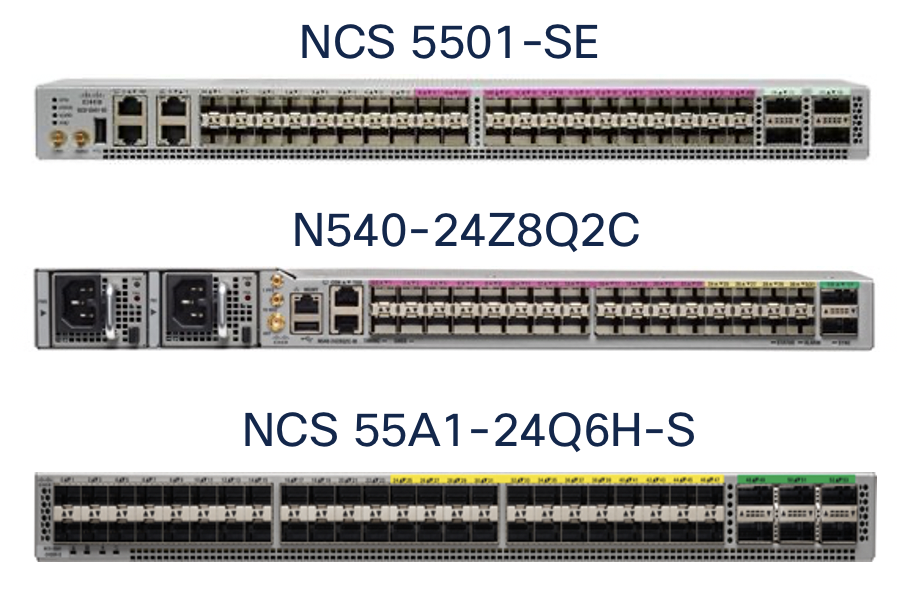
DPIC Aggregation
In larger deployments a DPIC aggregation leaf is recommended. Depending on the cBR8 DPIC card being used, a 10GE or 100GE aggregation device is required. The above RPD leaf devices can be utilized for high density DPIC 10GE aggregation. 100GE DPIC aggregation can also be served by the NCS-55A1-24H (24x100GE) or NCS-55A1-36H-S (36x100GE), or a variety of line cards for the NCS 5504 or 5508 modular chassis. All 100GE ports support 4x10GE breakouts for seamless migration to 100GE.
Aggregation Spine
The CIN aggregation spine router needs high density 100GE connectivity. Cisco has fixed or modular chassis variants supporting high density 100GE.
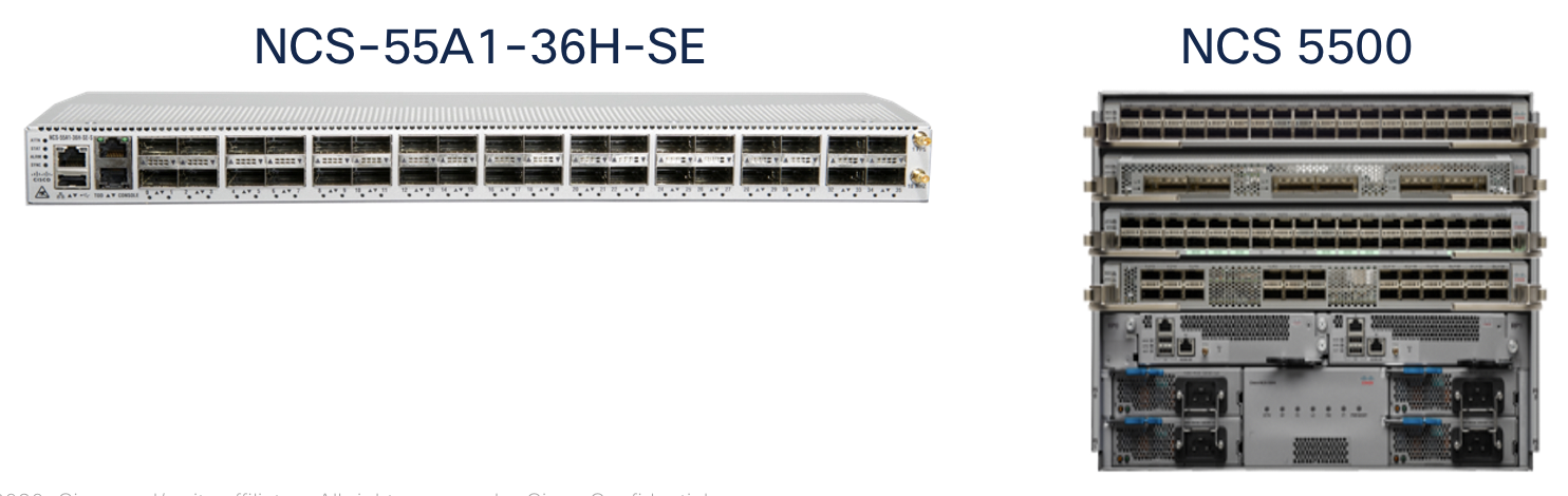
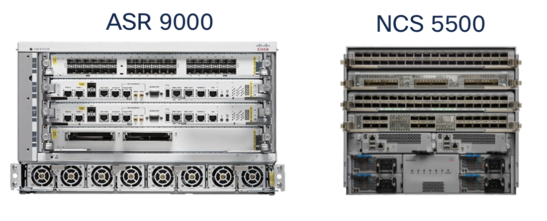
Core / PE
This device is typically used for cBR8 SUP uplinks. The ASR 9000 series or NCS 5500 can fulfill this role at high density including 400GE support.
Cable Converged Interconnect Network (CIN) High Level Design
Summary
The Converged SDN Transport Design enables a multi-service CIN by adding support for the features and functions required to build a scalable next-generation Ethernet/IP cable access network. Differentiated from simple switch or L3 aggregation designs is the ability to support NG cable transport over the same common infrastructure already supporting other services like mobile backhaul and business VPN services. Cable Remote PHY is simply another service overlayed onto the existing Converged SDN Transport network architecture. We will cover all aspects of connectivity between the Cisco cBR-8 and the RPD device.
Distributed Access Architecture
The cable Converged Interconnect Network is part of a next-generation Distributed Access Architecture (DAA), an architecture unlocking higher subscriber bandwidth by moving traditional cable functions deeper into the network closer to end users. R-PHY or Remote PHY, places the analog to digital conversion much closer to users, reducing the cable distance and thus enabling denser and higher order modulation used to achieve Gbps speeds over existing cable infrastructure. This reference design will cover the CIN design to support Remote PHY deployments.
Remote PHY Components and Requirements
This section will list some of the components of an R-PHY network and the network requirements driven by those components. It is not considered to be an exhaustive list of all R-PHY components, please see the CableLabs specification document, the latest which can be access via the following URL: https://specification-search.cablelabs.com/CM-SP-R-PHY
Remote PHY Device (RPD)
The RPD unlocks the benefits of DAA by integrating the physical analog to digital conversions in a device deployed either in the field or located in a shelf in a facility. The uplink side of the RPD or RPHY shelf is simply IP/Ethernet, allowing transport across widely deployed IP infrastructure. The RPD-enabled node puts the PHY function much closer to an end user, allowing higher end-user speeds. The shelf allows cable operators to terminate only the PHY function in a hub and place the CMTS/MAC function in a more centralized facility, driving efficiency in the hub and overall network. The following diagram shows various options for how RPDs or an RPD shelf can be deployed. Since the PHY function is split from the MAC it allows independent placement of those functions.
RPD Network Connections
Each RPD is typically deployed with a single 10GE uplink connection. The compact RPD shelf uses a single 10GE uplink for each RPD.
Cisco cBR-8 and cnBR
The Cisco Converged Broadband Router performs many functions as part of a Remote PHY solution. The cBR-8 provisions RPDs, originates L2TPv3 tunnels to RPDs, provisions cable modems, performs cable subscriber aggregation functions, and acts as the uplink L3 router to the rest of the service provider network. In the Remote PHY architecture the cBR-8 acts as the DOCSIS core and can also serve as a GCP server and video core. The cBR-8 runs IOS-XE. The cnBR, cloud native Broadband Router, provides DOCSIS core functionality in a server-based software platform deployable anywhere in the SP network. CST 3.0 has been validated using the cBR-8, the cnBR will be validated in an upcoming release.
cBR-8 Network Connections
The cBR-8 is best represented as having “upstream” and “downstream” connectivity.
The upstream connections are from the cBR8 Supervisor module to the SP network. Subscriber data traffic and video ingress these uplink connections for delivery to the cable access network. The cBR-8 SUP-160 has 8x10GE SFP+ physical connections, the SUP-250 has 2xQSFP28/QSFP+ interfaces for 40G/100G upstream connections.
In a remote PHY deployment the downstream connections to the CIN are via the Digital PIC (DPIC-8X10G) providing 40G of R-PHY throughput with 8 SFP+ network interfaces.
cBR-8 Redundancy
The cBR-8 supports both upstream and downstream redundancy. Supervisor redundancy uses active/standby connections to the SP network. Downstream redundancy can be configured at both the line card and port level. Line card redundancy uses an active/active mechanism where each RPD connects to the DOCSIS core function on both the active and hot standby Digital PIC line card. Port redundancy uses the concept of “port pairs” on each Digital PIC, with ports 0/1, 2/3, 4/6, and 6/7 using either an active/active (L2) or active/standby (L3) mechanism. In the CST design we utilize a L3 design with the active/standby mechanism. The mechanism uses the same IP address on both ports, with the standby port kept in a physical down state until switchover occurs.
Remote PHY Communication
DHCP
The RPD is provisioned using ZTP (Zero Touch Provisioning). DHCPv4 and DHCPv6 are used along with CableLabs DHCP options in order to attach the RPD to the correct GCP server for further provisioning.
Remote PHY Standard Flows
The following diagram shows the different core functions of a Remote PHY solution and the communication between those elements.
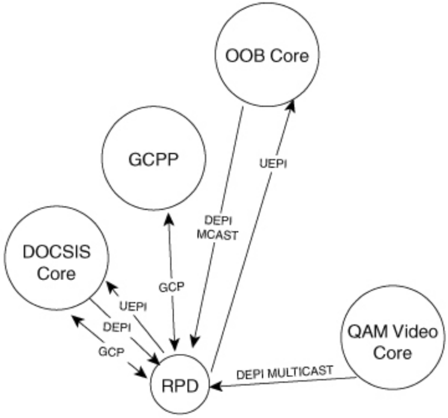
GCP
Generic Communications Protocol is used for the initial provisioning of the RPD. When the RPD boots and received its configuration via DHCP, one of the DHCP options will direct the RPD to a GCP server which can be the cBR-8 or Cisco Smart PHY. GCP runs over TCP typically on port 8190.
UEPI and DEPI L2TPv3 Tunnels
The upstream output from an RPD is IP/Ethernet, enabling the simplification of the cable access network. Tunnels are used between the RPD PHY functions and DOCSIS core components to transport signals from the RPD to the core elements, whether it be a hardware device like the Cisco cBR-8 or a virtual network function provided by the Cisco cnBR (cloud native Broadband Router).
DEPI (Downstream External PHY Interface) comes from the M-CMTS architecture, where a distributed architecture was used to scale CMTS functions. In the Remote PHY architecture DEPI represents a tunnel used to encapsulate and transport from the DOCSIS MAC function to the RPD. UEPI (Upstream External PHY Interface) is new to Remote PHY, and is used to encode and transport analog signals from the RPD to the MAC function.
In Remote PHY both DEPI and UEPI tunnels use L2TPv3, defined in RFC 3931, to transport frames over an IP infrastructure. Please see the following Cisco white paper for more information on how tunnels are created specific to upstream/downstream channels and how data is encoded in the specific tunnel sessions. https://www.cisco.com/c/en/us/solutions/collateral/service-provider/converged-cable-access-platform-ccap-solution/white-paper-c11-732260.html. In general there will be one or two (standby configuration) UEPI and DEPI L2TPv3 tunnels to each RPD, with each tunnel having many L2TPv3 sessions for individual RF channels identified by a unique session ID in the L2TPv3 header. Since L2TPv3 is its own protocol, no port number is used between endpoints, the endpoint IP addresses are used to identify each tunnel. Unicast DOCSIS data traffic can utilize either or multicast L2TPv3 tunnels. Multicast tunnels are used with downstream virtual splitting configurations. Multicast video is encoded and delivered using DEPI tunnels as well, using a multipoint L2TPv3 tunnel to multiple RPDs to optimize video delivery.
CIN Network Requirements
IPv4/IPv6 Unicast and Multicast
Due to the large number of elements and generally greenfield network builds, the CIN network must support all functions using both IPv4 and IPv6. IPv6 may be carried natively across the network or within an IPv6 VPN across an IPv4 MPLS underlay network. Similarly the network must support multicast traffic delivery for both IPv4 and IPv6 delivered via the global routing table or Multicast VPN. Scalable dynamic multicast requires the use of PIMv4, PIMv6, IGMPv3, and MLDv2 so these protocols are validated as part of the overall network design. IGMPv2 and MLDv2 snooping are also required for designs using access bridge domains and BVI interfaces for aggregation.
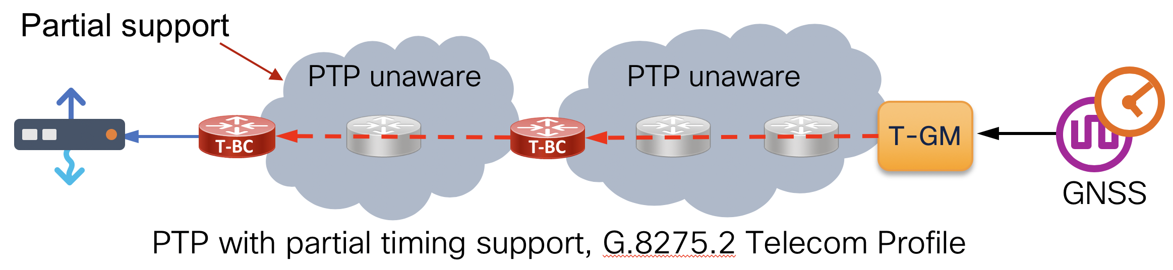
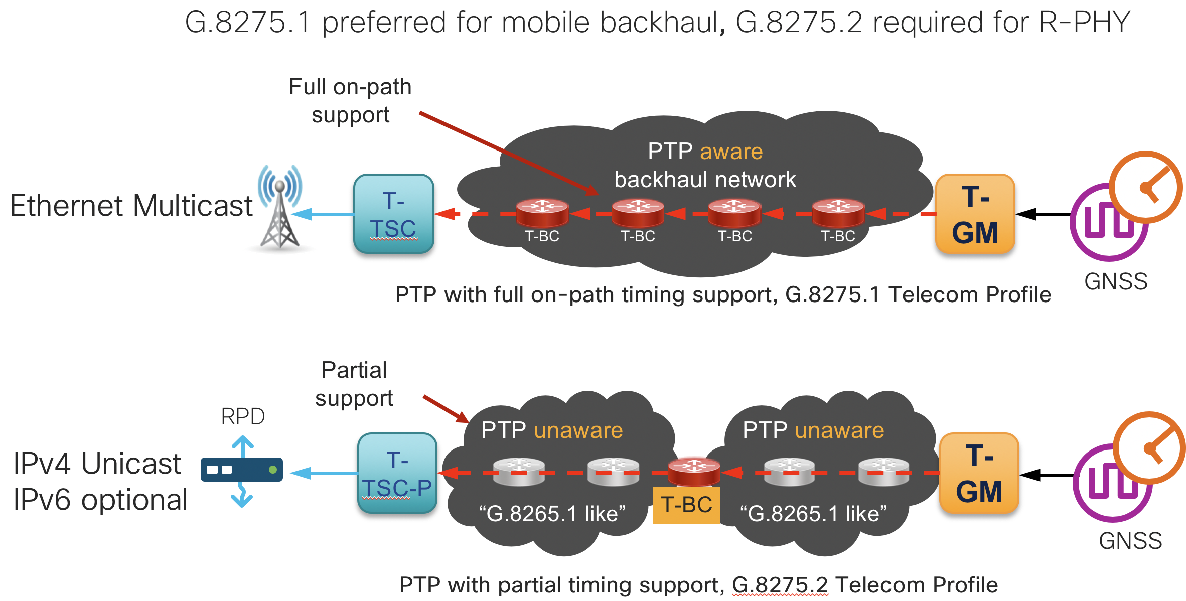
Network Timing
Frequency and phase synchronization is required between the cBR-8 and RPD to properly handle upstream scheduling and downstream transmission. Remote PHY uses PTP (Precision Timing Protocol) for timing synchronization with the ITU-T G.8275.2 timing profile. This profile carries PTP traffic over IP/UDP and supports a network with partial timing support, meaning multi-hop sessions between Grandmaster, Boundary Clocks, and clients as shown in the diagram below. The cBR-8 and its client RPD require timing alignment to the same Primary Reference Clock (PRC). In order to scale, the network itself must support PTP G.8275.2 as a T-BC (Boundary Clock). Synchronous Ethernet (SyncE) is also recommended across the CIN network to maintain stability when timing to the PRC.
QoS
Control plane functions of Remote PHY are critical to achieving proper operation and subscriber traffic throughput. QoS is required on all RPD-facing ports, the cBR-8 DPIC ports, and all core interfaces in between. Additional QoS may be necessary between the cBR-8, RPD, and any PTP timing elements. See the design section for further details on QoS components.
DHCPv4 and DHCPv6 Relay
As a critical component of the initial boot and provisioning of RPDs, the network must support DHCP relay functionality on all RPD-facing interfaces, for both IPv4 and IPv6.
Converged SDN Transport CIN Design
Deployment Topology Options
The Converged SDN Transport design is extremely flexible in how Remote PHY components are deployed. Depending on the size of the deployment, components can be deployed in a scalable leaf-spine fabric with dedicated routers for RPD and cBR-8 DPIC connections or collapsed into a single pair of routers for smaller deployments. If a smaller deployment needs to be expanded, the flexible L3 routed design makes it very easy to simply interconnect new devices and scale the design to a fabric supporting thousands of RPD and other access network connections.
High Scale Design (Recommended)
This option maximizes statistical multiplexing by aggregating Digital PIC downstream connections on a separate leaf device, allowing one to connect a number of cBR-8 interfaces to a fabric with minimal 100GE uplink capacity. The topology also supports the connectivity of remote shelves for hub consolidation. Another benefit is the fabric has optimal HA and the ability to easily scale with more leaf and spine nodes.
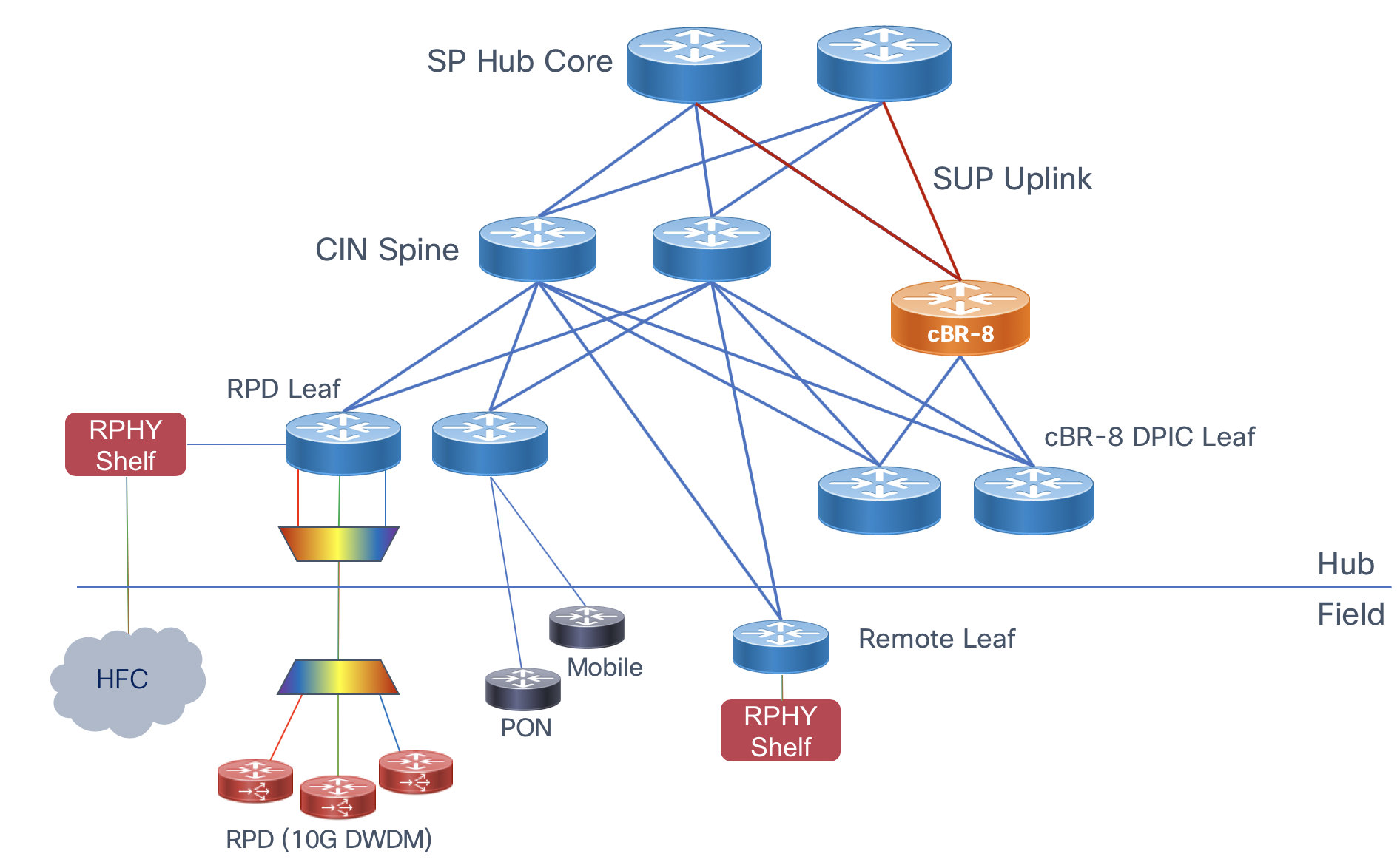 High scale topology
Collapsed Digital PIC and SUP Uplink Connectivity
This design for smaller deployments connects both the downstream Digital PIC connections and uplinks on the same CIN core device. If there is enough physical port availability and future growth does not dictate capacity beyond these nodes this design can be used. This design still provides full redundancy and the ability to connect RPDs to any cBR-8. Care should be taken to ensure traffic between the DPIC and RPD does not traverse the SUP uplink interfaces.
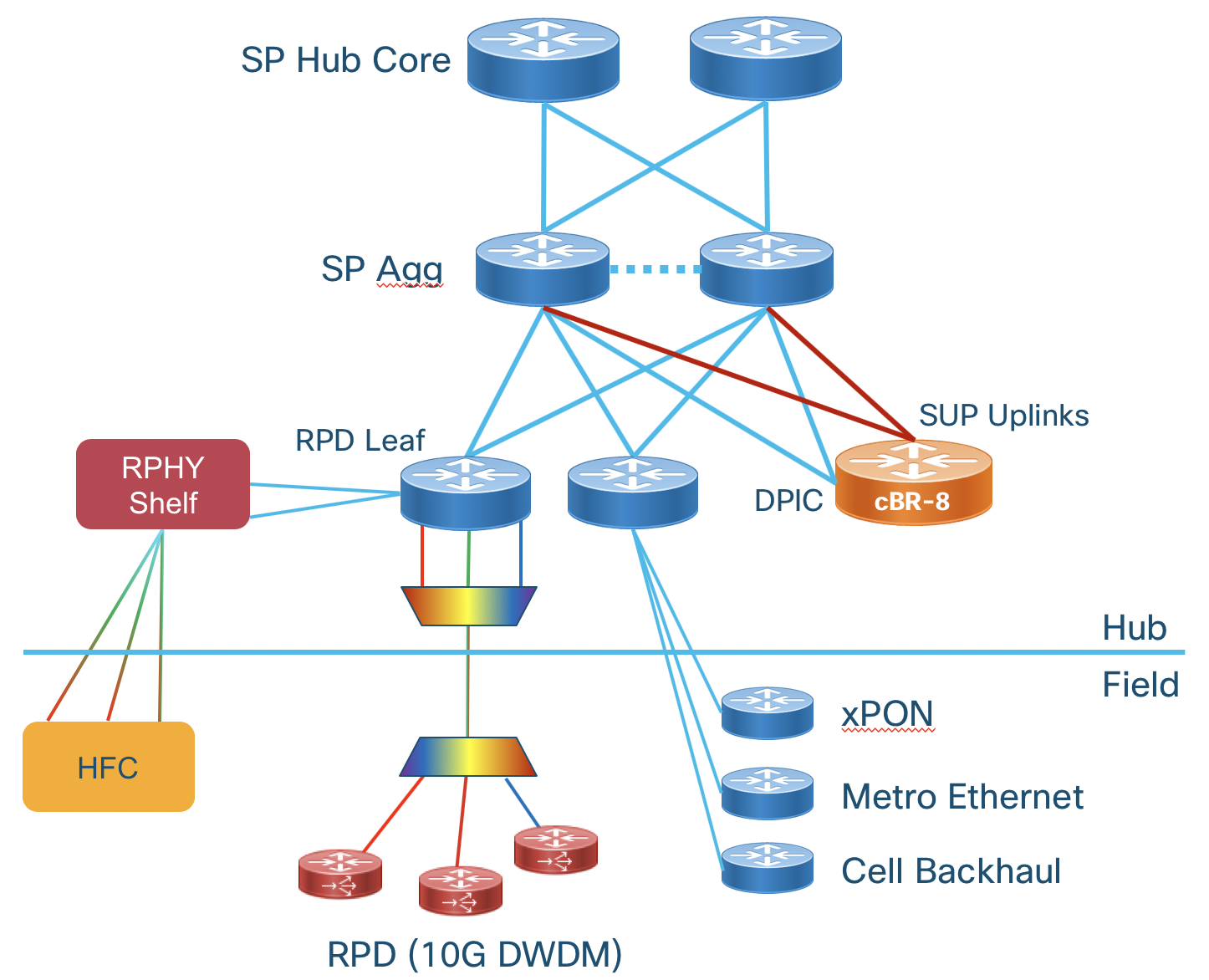 Collapsed cBR-8 uplink and Digital PIC connectivity
Collapsed RPD and cBR-8 DPIC Connectivity
This design connects each cBR-8 Digital PIC connection to the RPD leaf connected to the RPDs it will serve. This design can also be considered a “pod” design where cBR-8 and RPD connectivity is pre-planned. Careful planning is needed since the number of ports on a single device may not scale efficiently with bandwidth in this configuration.
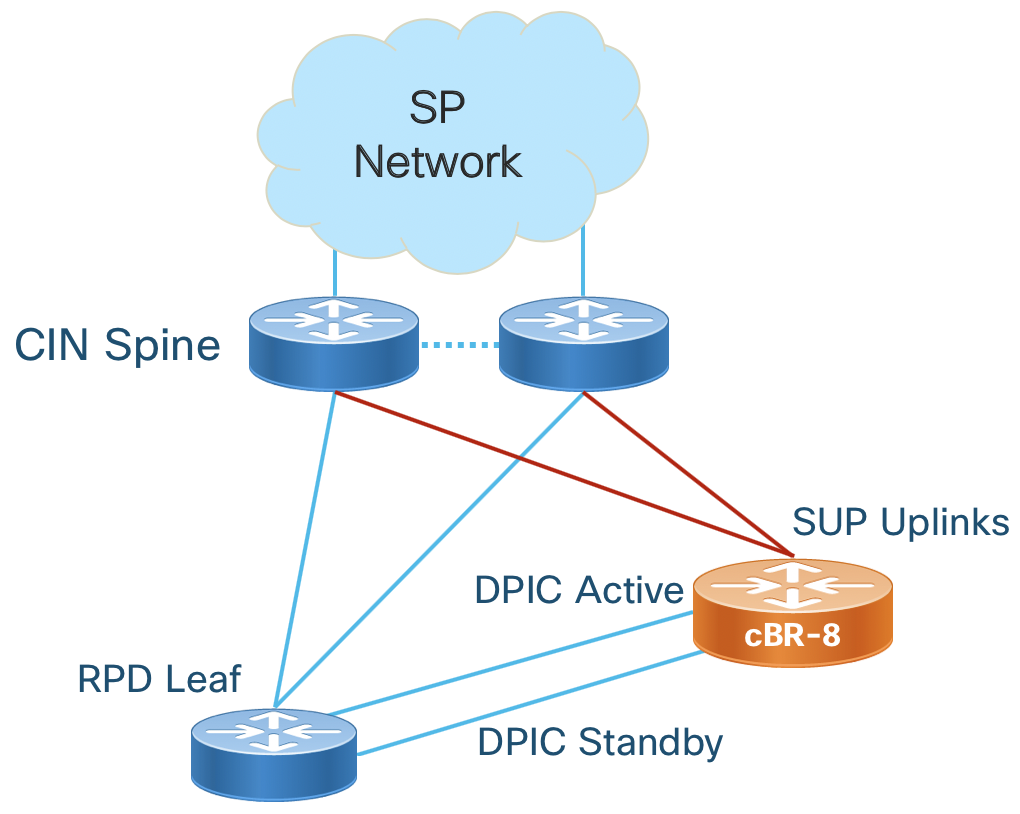 Collapsed or Pod cBR-8 Digital PIC and RPD connectivity
In the collapsed desigs care must be taken to ensure traffic between each RPD can reach the appropriate DPIC interface. If a leaf is single-homed to the aggregation router its DPIC interface is on, RPDs may not be able to reach their DPIC IP. The options with the shortest convergence time are: Adding interconnects between the agg devices or multiple uplinks from the leaf to agg devices.
Cisco Hardware
The following table highlights the Cisco hardware utilized within the Converged SDN Transport design for Remote PHY. This table is non-exhaustive. One highlight is all NCS platforms listed are built using the same NPU family and share most features across all platforms. See specific platforms for supported scale and feature support.
| Product | Role | 10GE SFP+ | 25G SFP28 | 100G QSFP28 | Timing | Comments |
|---|---|---|---|---|---|---|
| NCS-55A1-24Q6H-S | RPD leaf | 48 | 24 | 6 | Class B | |
| N540-ACC-SYS | RPD leaf | 24 | 8 | 2 | Class B | Smaller deployments |
| N540-28Z4C-A/D | RPD leaf | 28 | 0 | 4 | Class B | Smaller deployments |
| NCS-55A1-48Q6H-S | DPIC leaf | 48 | 48 | 6 | Class B | |
| NCS-55A2-MOD | Remote agg | 40 | 24 | upto 8 | Class B | CFP2-DCO support |
| NCS-55A1-36H-S | Spine | 144 (breakout) | 0 | 36 | Class B | |
| NCS-5502 | Spine | 192 (breakout) | 0 | 48 | None | |
| NCS-5504 | Multi | Upto 576 | x | Upto 144 | Class B | 4-slot modular platform |
Scalable L3 Routed Design
The Cisco validated design for cable CIN utilizes a L3 design with or without Segment Routing. Pure L2 networks are no longer used for most networks due to their inability to scale, troubleshooting difficulty, poor network efficiency, and poor resiliency. L2 bridging can be utilized on RPD aggregation routers to simplify RPD connectivity.
L3 IP Routing
Like the overall CST design, we utilize IS-IS for IPv4 and IPv6 underlay routing and BGP to carry endpoint information across the network. The following diagram illustrates routing between network elements using a reference deployment. The table below describes the routing between different functions and interfaces. See the implementation guide for specific configuration.
| Interface | Routing | Comments |
|---|---|---|
| cBR-8 Uplink | IS-IS | Used for BGP next-hop reachability to SP Core |
| cBR-8 Uplink | BGP | Advertise subscriber and cable-modem routes to SP Core |
| cBR-8 DPIC | Static default in VRF | Each DPIC interface should be in its own VRF on the cBR-8 so it has a single routing path to its connected RPDs |
| RPD Leaf Main | IS-IS | Used for BGP next-hop reachability |
| RPD Leaf Main | BGP | Advertise RPD L3 interfaces to CIN for cBR-8 to RPD connectivity |
| RPD Leaf Timing | BGP | Advertise RPD upstream timing interface IP to rest of network |
| DPIC Leaf | IS-IS | Used for BGP next-hop reachability |
| DPIC Leaf | BGP | Advertise cBR-8 DPIC L3 interfaces to CIN for cBR-8 to RPD connectivity |
| CIN Spine | IS-IS | Used for reachability between BGP endpoints, the CIN Spine does not participate in BGP in a SR-enabled network |
| CIN Spine RPD Timing | IS-IS | Used to advertise RPD timing interface BGP next-hop information and advertise default |
| CIN Spine | BGP (optional) | In a native IP design the spine must learn BGP routes for proper forwarding |
CIN Router to Router Interconnection
It is recommended to use multiple L3 links when interconnecting adjacent routers, as opposed to using LAG, if possible. Bundles increase the possibility for timing inaccuracy due to asymmetric timing traffic flow between slave and master. If bundle interfaces are utilized, care should be taken to ensure the difference in paths between two member links is kept to a minimum. All router links will be configured according to the global CST design. Leaf devices will be considered CST access PE devices and utilize BGP for all services routing.
Leaf Transit Traffic
In a single IGP network with equal IGP metrics, certain link failures may cause a leaf to become a transit node. Several options are available to keep transit traffic from transiting a leaf and potentially causing congestion. Using high metrics on all leaf to agg uplinks will prohibit this and is recommended in all configurations.
cBR-8 DPIC to CIN Interconnection
The cBR-8 supports two mechanisms for DPIC high availability outlined in the overview section. DPIC line card and link redundancy is recommended but not a requirement. In the CST reference design, if link redundancy is being used each port pair on the active and standby line cards is connected to a different router and the default active ports (even port number) is connected to a different router. In the example figure, port 0 from active DPIC card 0 is connected to R1 and port 0 from standby DPIC card 1 is connected to R2. DPIC link redundancy MUST be configured using the “cold” method since the design is using L3 to each DPIC interface and no intermediate L2 switching. This is done with the cable rphy link redundancy cold global command and will keep the standby link in a down/down state until switchover occurs.
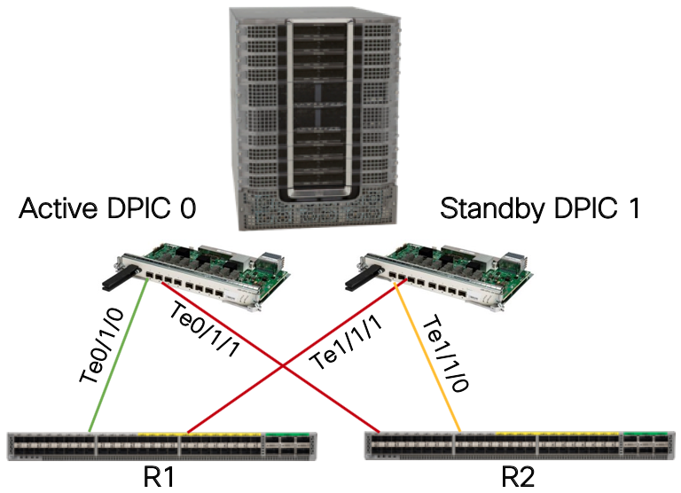 DPIC line card and link HA
DPIC Interface Configuration
Each DPIC interface should be configured in its own L3 VRF. This ensures traffic from an RPD assigned to a specific DPIC interface takes the traffic path via the specific interface and does not traverse the SUP interface for either ingress or egress traffic. It’s recommended to use a static default route within each DPIC VRF towards the CIN network. Dynamic routing protocols could be utilized, however it will slow convergence during redundancy switchover.
Router Interface Configuration
If no link redundancy is utilized each DPIC interface will connect to the router using a point to point L3 interface.
If using cBR-8 link HA, failover time is reduced by utilizing the same gateway MAC address on each router. Link HA uses the same IP and MAC address on each port pair on the cBR-8, and retains routing and ARP information for the L3 gateway. If a different MAC address is used on each router, traffic will be dropped until an ARP occurs to populate the GW MAC address on the router after failover. On the NCS platforms, a static MAC address cannot be set on a physical L3 interface. The method used to set a static MAC address is to use a BVI (Bridged Virtual Interface), which allows one to set a static MAC address. In the case of DPIC interface connectivity, each DPIC interface should be placed into its own bridge domain with an associated BVI interface. Since each DPIC port is directly connected to the router interface, the same MAC address can be utilized on each BVI.
If using IS-IS to distribute routes across the CIN, each DPIC physical interface or BVI should be configured as a passive IS-IS interface in the topology. If using BGP to distribute routing information the “redistribute connected” command should be used with an appropriate route policy to restrict connected routes to only DPIC interface. The BGP configuration is the same whether using L3VPN or the global routing table.
It is recommended to use a /31 for IPv4 and /127 for IPv6 addresses for each DPIC port whether using a L3 physical interface or BVI on the CIN router.
RPD to Router Interconnection
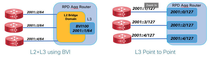
The Converged SDN Transport design supports both P2P L3 interfaces for RPD and DPIC aggregation as well as using Bridge Virtual Interfaces. A BVI is a logical L3 interface within a L2 bridge domain. In the BVI deployment the DPIC and RPD physical interfaces connected to a single leaf device share a common IP subnet with the gateway residing on the leaf router.
It is recommended to configure the RPD leaf using bridge-domains and BVI interfaces. This eases configuration on the leaf device as well as the DHCP configuration used for RPD provisioning.
The following shows the P2P and BVI deployment options.
Native IP or L3VPN/mVPN Deployment
Two options are available and validated to carry Remote PHY traffic between the RPD and MAC function.
Native IP means the end to end communication occurs as part of the global routing table. In a network with SR-MPLS deployed such as the CST design, unicast IP traffic is still carried across the network using an MPLS header. This allows for fast reconvergence in the network by using SR and enabled the network to carry other VPN services on the network even if they are not used to carry Remote PHY traffic. In then native IP deployment, multicast traffic uses either PIM signaling with IP multicast forwarding or mLDP in-band signaling for label-switched multicast. The multicast profile used is profile 7 (Global mLDP in-band signaling).
L3VPN and mVPN can also be utilized to carry Remote PHY traffic within a VPN service end to end. This has the benefit of separating Remote PHY traffic from the network underlay, improving security and treating Remote PHY as another service on a converged access network. Multicast traffic in this use case uses mVPN profile 14. mLDP is used for label-switched multicast, and the NG-MVPN BGP control plane is used for all multicast discovery and signaling.
SR-TE
Segment Routing Traffic Engineering may be utilized to carry traffic end to end across the CIN network. Using On-Demand Networking simplifies the deployment of SR-TE Policies from ingress to egress by using specific color BGP communities to instruct head-end nodes to create policies satisfying specific user constraints. As an example, if RPD aggregation prefixes are advertised using BGP to the DPIC aggregation device, SR-TE tunnels following a user constraint can be built dynamically between those endpoints.
CIN Quality of Service (QoS)
QoS is a requirement for delivering trouble-free Remote PHY. This design uses sample QoS configurations for concept illustration, but QoS should be tailored for specific network deployments. New CIN builds can utilize the configurations in the implementation guide verbatim if no other services are being carried across the network. Please see the section in this document on QoS for general NCS QoS information and the implementation guide for specific details.
CST Network Traffic Classification
The following lists specific traffic types which should be treated with specific priority, default markings, and network classification points.
| Traffic Type | Ingress Interface | Priority | Default Marking | Comments |
|---|---|---|---|---|
| BGP | Routers, cBR-8 | Highest | CS6 (DSCP 48) | None |
| IS-IS | Routers, cBR-8 | Highest | CS6 | IS-IS is single-hop and uses highest priority queue by default |
| BFD | Routers | Highest | CS6 | BFD is single-hop and uses highest priority queue by default |
| DHCP | RPD | High | CS5 | DHCP COS is set explicitly |
| PTP | All | High | DSCP 46 | Default on all routers, cBR-8, and RPD |
| DOCSIS MAP/UCD | RPD, cBR-8 DPIC | High | DSCP 46 | |
| DOCSIS BWR | RPD, cBR-8 DPIC | High | DSCP 46 | |
| GCP | RPD, cBR-8 DPIC | Low | DSCP 0 | |
| DOCSIS Data | RPD, cBR-8 DPIC | Low | DSCP 0 | |
| Video | cBR-8 | Medium | DSCP 32 | Video within multicast L2TPv3 tunnel when cBR-8 is video core |
| MDD | RPD, cBR-8 | Medium | DSCP 40 |
CST and Remote-PHY Load Balancing
Unicast network traffic is load balanced based on MPLS labels and IP header criteria. The devices used in the CST design are capable of load balancing traffic based on MPLS labels used in the SR underlay and IP headers underneath any MPLS labels. In the higher bandwidth downstream direction, where a series of L2TP3 tunnels are created from the cBR-8 to the RPD, traffic is hashed based on the source and destination IP addresses of those tunnels. Downstream L2TPv3 tunnels from a single Digital PIC interface to a set of RPDs will be distributed across the fabric based on RPD destination IP address. The followUing illustrates unicast load balancing across the network.

Multicast traffic is not load balanced across the network. Whether the network is utilizing PIMv4, PIMv6, or mVPN, a multicast flow with two equal cost downstream paths will utilize only a single path, and only a single member link will be utilized in a link bundle. If using multicast, ensure sufficient bandwidth is available on a single link between two adjacencies.
Low-Level CIN Design and Configuration
IOS-XR Nodes - SR-MPLS Transport
Underlay physical interface configuration with BFD
interface TenGigE0/0/0/10
 bfd mode ietf
 bfd address-family ipv4 timers start 180
 bfd address-family ipv4 multiplier 3
 bfd address-family ipv4 destination 10.1.2.1
 bfd address-family ipv4 fast-detect
 bfd address-family ipv4 minimum-interval 50
 mtu 9216
 ipv4 address 10.15.150.1 255.255.255.254
 ipv4 unreachables disable
 load-interval 30
 dampening
SRGB and SRLB Definition
It’s recommended to first configure the Segment Routing Global Block (SRGB) across all nodes needing connectivity between each other. In most instances a single SRGB will be used across the entire network. In a SR MPLS deployment the SRGB and SRLB correspond to the label blocks allocated to SR. IOS-XR has a maximum configurable SRGB limit of 512,000 labels, however please consult platform-specific documentation for maximum values. The SRLB corresponds to the labels allocated for SIDs local to the node, such as Adjacency-SIDs. It is recommended to configure the same SRLB block across all nodes. The SRLB must not overlap with the SRGB. The SRGB and SRLB are configured in IOS-XR with the following configuration:
segment-routing
 global-block 16000 23999
 local-block 15000 15999
IGP protocol (ISIS) and Segment Routing MPLS configuration
Key chain global configuration for IS-IS authentication
key chain ISIS-KEY
 key 1
 accept-lifetime 00:00:00 january 01 2018 infinite
 key-string password 00071A150754
 send-lifetime 00:00:00 january 01 2018 infinite
 cryptographic-algorithm HMAC-MD5
IS-IS router configuration
All routers, except Area Border Routers (ABRs), are part of one IGP domain and L2 area (ISIS-ACCESS or ISIS-CORE). Area border routers
run two IGP IS-IS processes (ISIS-ACCESS and ISIS-CORE). Note that Loopback0 is part of both IGP processes.
router isis ISIS-ACCESS
 set-overload-bit on-startup 360
 is-type level-2-only
 net 49.0001.0101.0000.0110.00
 nsr
 nsf cisco
 log adjacency changes
 lsp-gen-interval maximum-wait 5000 initial-wait 5 secondary-wait 100
 lsp-refresh-interval 65000
 max-lsp-lifetime 65535
 address-family ipv4 unicast
  metric-style wide
  advertise link attributes
  spf-interval maximum-wait 1000 initial-wait 5 secondary-wait 100
  segment-routing mpls
  spf prefix-priority high tag 1000
  maximum-redistributed-prefixes 100 level 2
 !
 address-family ipv6 unicast
  metric-style wide
  spf-interval maximum-wait 5000 initial-wait 50 secondary-wait 200
  maximum-redistributed-prefixes 100 level 2
Note: ABR Loopback 0 on domain boundary is part of both IGP processes together with same “prefix-sid absolute” value, giving resiliency to the border.
Note: The prefix SID can be configured as either absolute or index. The index configuration is required for interop with nodes using a different SRGB.
IS-IS Loopback and node SID configuration
 interface Loopback0
  ipv4 address 100.0.1.50 255.255.255.255
  address-family ipv4 unicast
   prefix-sid absolute 16150
   tag 1000
IS-IS interface configuration with TI-LFA
It is recommended to use manual adjacency SIDs. A protected SID is eligible for backup path computation, meaning if a packet ingresses the node with the label a backup path will be provided in case of a failure. In the case of having multiple adjacencies between the same two nodes, use the same adjacency-sid on each link.
 interface TenGigE0/0/0/10
  point-to-point
  hello-password keychain ISIS-KEY
  address-family ipv4 unicast
   fast-reroute per-prefix
   fast-reroute per-prefix ti-lfa
   adjacency-sid absolute 15002 protected
   metric 100
  !
  address-family ipv6 unicast
   fast-reroute per-prefix
   fast-reroute per-prefix ti-lfa
   metric 100
Multicast transport using mLDP
Overview
This portion of the implementation guide instructs the user how to configure mLDP end to end across the multi-domain network. Multicast service examples are given in the “Services” section of the implementation guide.
mLDP core configuration
In order to use mLDP across the Converged SDN Transport network LDP must first be enabled. There are two mechanisms to enable LDP on physical interfaces across the network, LDP auto-configuration or manually under the MPLS LDP configuration context. The capabilities statement will ensure LDP unicast FECs are not advertised, only mLDP FECs. Recursive forwarding is required in a multi-domain network. mLDP must be enabled on all participating A-PE, PE, AG, PA, and P routers.
LDP base configuration with defined interfaces
mpls ldp
 capabilities sac mldp-only
 mldp
  logging notifications
  address-family ipv4
   make-before-break delay 30
   forwarding recursive
   recursive-fec
  !
 !
 router-id 100.0.2.53
 session protection
 address-family ipv4
 !
 interface TenGigE0/0/0/6
 !
 interface TenGigE0/0/0/7
LDP auto-configuration
LDP can automatically be enabled on all IS-IS interfaces with the following configuration in the IS-IS configuration. It is recommended to do this only after configuring all MPLS LDP properties.
router isis ACCESS
  address-family ipv4 unicast
    segment-routing mpls sr-prefer
    mpls ldp auto-config
G.8275.2 PTP (1588v2) timing configuration
Summary
This section contains the base configurations used for both G.8275.1 and G.8275.2 timing. Please see the CST 3.0 HLD for an overview on timing in general.
Enable frequency synchronization
In order to lock the internal oscillator to a PTP source, frequency synchronization must first be enabled globally.
frequency synchronization
 quality itu-t option 1
 clock-interface timing-mode system
 log selection changes
!
Optional Synchronous Ethernet configuration (PTP hybrid mode)
If the end-to-end devices support SyncE it should be enabled. SyncE will allow much faster frequency sync and maintain integrity for long periods of time during holdover events. Using SyncE for frequency and PTP for phase is known as “Hybrid” mode. A lower priority is used on the SyncE input (50 for SyncE vs. 100 for PTP).
interface TenGigE0/0/0/10
 frequency synchronization
  selection input
  priority 50
 !
!
PTP G.8275.2 global timing configuration
As of CST 3.0, IOS-XR supports a single PTP timing profile and single clock type in the global PTP configuration. The clock domain should follow the ITU-T guidelines for specific profiles using a domain >44 for G.8275.2 clocks.
ptp
 clock
  domain 60
  profile g.8275.2 clock-type T-BC
  !
 frequency priority 100
 time-of-day priority 50
 log
  servo events
  best-master-clock changes
 !
PTP G.8275.2 interface profile definitions
It is recommended to use “profiles” defined globally which are then applied to interfaces participating in timing. This helps minimize per-interface timing configuration. It is also recommended to define different profiles for “master” and “slave” interfaces.
IPv4 G.8275.2 master profile
The master profile is assigned to interfaces for which the router is acting as a boundary clock
ptp
 profile g82752_master_v4
  transport ipv4
  port state master-only
  sync frequency 16
  clock operation one-step <-- Note the NCS series should be configured with one-step, ASR9000 with two-step
  announce timeout 5
  announce interval 1
  unicast-grant invalid-request deny
  delay-request frequency 16
 !
!
IPv6 G.8275.2 master profile
The master profile is assigned to interfaces for which the router is acting as a boundary clock
ptp
 profile g82752_master_v6
  transport ipv6
  port state master-only
  sync frequency 16
  clock operation one-step
  announce timeout 10
  announce interval 1
  unicast-grant invalid-request deny
  delay-request frequency 16
 !
!
IPv4 G.8275.2 slave profile
The slave profile is assigned to interfaces for which the router is acting as a slave to another master clock
ptp
 profile g82752_master_v4
  transport ipv4
  port state slave-only
  sync frequency 16
  clock operation one-step <-- Note the NCS series should be configured with one-step, ASR9000 with two-step
  announce timeout 10
  announce interval 1
  unicast-grant invalid-request deny
  delay-request frequency 16
 !
!
IPv6 G.8275.2 slave profile
The slave profile is assigned to interfaces for which the router is acting as a slave to another master clock
ptp
 profile g82752_master_v6
  transport ipv6
  port state slave-only
  sync frequency 16
  clock operation one-step <-- Note the NCS series should be configured with one-step, ASR9000 with two-step
  announce timeout 10
  announce interval 1
  unicast-grant invalid-request deny
  delay-request frequency 16
 !
!
Application of G.8275.2 PTP profile to physical interface
Note: In CST 3.0 PTP may only be enabled on physical interfaces. G.8275.1 operates at L2 and supports PTP across Bundle member links and interfaces part of a bridge domain. G.8275.2 operates at L3 and does not support Bundle interfaces or BVI interfaces.
G.8275.2 interface configuration
This example is of a slave device using a master of 2405:10:23:253::0.
interface TenGigE0/0/0/6
 ptp
  profile g82752_slave_v6
  master ipv6 2405:10:23:253::
  !
 !
CIN Remote-PHY Specific Deployment Configuration
Summary
Detail can be found in the CST 3.0 high-level design guide for design decisions, this section will provide sample configurations.
Sample QoS Policies
The following are usable policies but policies should be tailored for specific network deployments.
Class maps
Class maps are used within a policy map to match packet criteria for further treatment
class-map match-any match-ef-exp5
 description High priority, EF
 match dscp 46
 match mpls experimental topmost 5
 end-class-map
!
class-map match-any match-cs5-exp4
 description Second highest priority
 match dscp 40
 match mpls experimental topmost 4
 end-class-map
!
class-map match-any match-video-cs4-exp2
 description Video
 match dscp 32
 match mpls experimental topmost 2
 end-class-map
!
class-map match-any match-cs6-exp6
 description Highest priority control-plane traffic
 match dscp cs6
 match mpls experimental topmost 6
 end-class-map
!
class-map match-any match-qos-group-1
 match qos-group 1
 end-class-map
!
class-map match-any match-qos-group-2
 match qos-group 2
 end-class-map
!
class-map match-any match-qos-group-3
 match qos-group 3
 end-class-map
!
class-map match-any match-qos-group-6
 match qos-group 3
 end-class-map
!
class-map match-any match-traffic-class-1
 description "Match highest priority traffic-class 1"
 match traffic-class 1
 end-class-map
!
class-map match-any match-traffic-class-2
 description "Match high priority traffic-class 2"
 match traffic-class 2
 end-class-map
!
class-map match-any match-traffic-class-3
 description "Match medium traffic-class 3"
 match traffic-class 3
 end-class-map
!
class-map match-any match-traffic-class-6
 description "Match video traffic-class 6"
 match traffic-class 6
 end-class-map
RPD and DPIC interface policy maps
These are applied to all interfaces connected to cBR-8 DPIC and RPD devices.
Note: Egress queueing maps are not supported on L3 BVI interfaces
RPD/DPIC ingress classifier policy map
policy-map rpd-dpic-ingress-classifier
 class match-cs6-exp6
  set traffic-class 1
  set qos-group 1
 !
 class match-ef-exp5
  set traffic-class 2
  set qos-group 2
 !
 class match-cs5-exp4
  set traffic-class 3
  set qos-group 3
 !
 class match-video-cs4-exp2
  set traffic-class 6
  set qos-group 6
 !
 class class-default
  set traffic-class 0
  set dscp 0
  set qos-group 0
 !
 end-policy-map
!
P2P RPD and DPIC egress queueing policy map
policy-map rpd-dpic-egress-queuing
 class match-traffic-class-1
  priority level 1
  queue-limit 500 us
 !
 class match-traffic-class-2
  priority level 2
  queue-limit 100 us
 !
 class match-traffic-class-3
  priority level 3
  queue-limit 500 us
 !
 class match-traffic-class-6
  priority level 6
  queue-limit 500 us
 !
 class class-default
  queue-limit 250 ms
 !
 end-policy-map
!
Core QoS
Please see the general QoS section for core-facing QoS configuration
CIN Timing Configuration
Please see the G.8275.2 timing configuration guide in this document for details on timing configuration. The following values should be used for PTP configuration attributes. Please note in CST 3.0 the use of an IOS-XR router as a Boundary Clock is only supported on P2P L3 interfaces. The use of a BVI for RPD aggregation requires the BC used for RPD nodes be located upstream, or alternatively a physical loopback cable may be used to provide timing off the IOS-XR based RPD leaf device.
| PTP variable | IOS-XR configuration value | IOS-XE value |
|---|---|---|
| Announce Interval | 1 | 1 |
| Announce Timeout | 5 | 5 |
| Sync Frequency | 16 | -4 |
| Delay Request Frequency | 16 | -4 |
Example CBR-8 RPD DTI Profile
ptp r-dti 4
 profile G.8275.2
 ptp-domain 60
 clock-port 1
   clock source ip 192.168.3.1
   sync interval -4
   announce timeout 5
   delay-req interval -4
Multicast configuration
Summary
We present two different configuration options based on either native multicast deployment or the use of a L3VPN to carry Remote PHY traffic. The L3VPN option shown uses Label Switched Multicast profile 14 (partitioned mLDP) however profile 6 could also be utilized.
Global multicast configuration - Native multicast
On CIN aggregation nodes all interfaces should have multicast enabled.
multicast-routing
 address-family ipv4
  interface all enable
 !
 address-family ipv6
  interface all enable
   enable
 !
Global multicast configuration - LSM using profile 14
On CIN aggregation nodes all interfaces should have multicast enabled.
vrf VRF-MLDP
  address-family ipv4
   mdt source Loopback0
   rate-per-route
   interface all enable
   accounting per-prefix
   bgp auto-discovery mldp
   !
   mdt partitioned mldp ipv4 p2mp
   mdt data 100
  !
 !
PIM configuration - Native multicast
PIM should be enabled for IPv4/IPv6 on all core facing interfaces
router pim
 address-family ipv4
  interface Loopback0
   enable
  !
  interface TenGigE0/0/0/6
   enable
  !
  interface TenGigE0/0/0/7
   enable
  !
 !
PIM configuration - LSM using profile 14
The PIM configuration is utilized even though no PIM neighbors may be connected.
route-policy mldp-partitioned-p2mp
  set core-tree mldp-partitioned-p2mp
end-policy
!
router pim
 address-family ipv4
  interface Loopback0
   enable
 vrf rphy-vrf
  address-family ipv4
   rpf topology route-policy mldp-partitioned-p2mp
   mdt c-multicast-routing bgp
   !
  !
IGMPv3/MLDv2 configuration - Native multicast
Interfaces connected to RPD and DPIC interfaces should have IGMPv3 and MLDv2 enabled
router igmp
 interface BVI100
  version 3
 !
 interface TenGigE0/0/0/25
  version 3
 !
!
router mld
 interface BVI100
  version 2
 interface TenGigE0/0/0/25
  version 3
 !
 !
IGMPv3/MLDv2 configuration - LSM profile 14
Interfaces connected to RPD and DPIC interfaces should have IGMPv3 and MLDv2 enabled as needed
router igmp
 vrf rphy-vrf
  interface BVI101
   version 3
  !
  interface TenGigE0/0/0/15
  !
 !
!
router mld
 vrf rphy-vrf
  interface TenGigE0/0/0/15
   version 2
  !
 !
!
IGMPv3 / MLDv2 snooping profile configuration (BVI aggregation)
In order to limit L2 multicast replication for specific groups to only interfaces with interested receivers, IGMP and MLD snooping must be enabled.
igmp snooping profile igmp-snoop-1
!
mld snooping profile mld-snoop-1
!
RPD DHCPv4/v6 relay configuration
In order for RPDs to self-provision DHCP relay must be enabled on all RPD-facing L3 interfaces. In IOS-XR the DHCP relay configuration is done in its own configuration context without any configuration on the interface itself.
Native IP / Default VRF
dhcp ipv4
 profile rpd-dhcpv4 relay
  helper-address vrf default 10.0.2.3
 !
 interface BVI100 relay profile rpd-dhcpv4
!
dhcp ipv6
 profile rpd-dhcpv6 relay
  helper-address vrf default 2001:10:0:2::3
  iana-route-add
  source-interface BVI100
 !
 interface BVI100 relay profile rpd-dhcpv6
RPHY L3VPN
In this example it is assumed the DHCP server exists within the rphy-vrf VRF, if it does not then additional routing may be necessary to forward packets between VRFs.
dhcp ipv4
 vrf rphy-vrf relay profile rpd-dhcpv4-vrf
 profile rpd-dhcpv4-vrf relay
  helper-address vrf rphy-vrf 10.0.2.3
  relay information option allow-untrusted
 !
 inner-cos 5
 outer-cos 5
 interface BVI101 relay profile rpd-dhcpv4-vrf
 interface TenGigE0/0/0/15 relay profile rpd-dhcpv4-vrf
!
cBR-8 DPIC interface configuration without Link HA
Without link HA the DPIC port is configured as a normal physical interface
interface TenGigE0/0/0/25
 description .. Connected to cbr8 port te1/1/0
 service-policy input rpd-dpic-ingress-classifier
 service-policy output rpd-dpic-egress-queuing
 ipv4 address 4.4.9.101 255.255.255.0
 ipv6 address 2001:4:4:9::101/64
 carrier-delay up 0 down 0
 load-interval 30
cBR-8 DPIC interface configuration with Link HA
When using Link HA faster convergence is achieved when each DPIC interface is placed into a BVI with a statically assigned MAC address. Each DPIC interface is placed into a separate bridge-domain with a unique BVI L3 interface. The same MAC address should be utilized on all BVI interfaces. Convergence using BVI interfaces is <50ms, L3 physical interfaces is 1-2s.
Even DPIC port CIN interface configuration
interface TenGigE0/0/0/25
 description "Connected to cBR8 port Te1/1/0"
 lldp
 !
 carrier-delay up 0 down 0
 load-interval 30
 l2transport
 !
!
l2vpn
 bridge group cbr8
  bridge-domain port-ha-0
   interface TenGigE0/0/0/25
   !
   routed interface BVI500
   !
  !
 !
 interface BVI500
 description "BVI for cBR8 port HA, requires static MAC"
 service-policy input rpd-dpic-ingress-classifier
 ipv4 address 4.4.9.101 255.255.255.0
 ipv6 address 2001:4:4:9::101/64
 mac-address 8a.9698.64
 load-interval 30
!
Odd DPIC port CIN interface configuration
interface TenGigE0/0/0/26
 description "Connected to cBR8 port Te1/1/1"
 lldp
 !
 carrier-delay up 0 down 0
 load-interval 30
 l2transport
 !
!
l2vpn
 bridge group cbr8
  bridge-domain port-ha-1
   interface TenGigE0/0/0/26
   !
   routed interface BVI501
   !
  !
 !
 interface BVI501
 description "BVI for cBR8 port HA, requires static MAC"
 service-policy input rpd-dpic-ingress-classifier
 ipv4 address 4.4.9.101 255.255.255.0
 ipv6 address 2001:4:4:9::101/64
 mac-address 8a.9698.64
 load-interval 30
!
cBR-8 Digital PIC Interface Configuration
interface TenGigE0/0/0/25
 description .. Connected to cbr8 port te1/1/0
 service-policy input rpd-dpic-ingress-classifier
 service-policy output rpd-dpic-egress-queuing
 ipv4 address 4.4.9.101 255.255.255.0
 ipv6 address 2001:4:4:9::101/64
 carrier-delay up 0 down 0
 load-interval 30
RPD interface configuration
P2P L3
In this example the interface has PTP enabled towards the RPD
interface TeGigE0/0/0/15
 description To RPD-1
 mtu 9200
 ptp
  profile g82752_master_v4
 !
 service-policy input rpd-dpic-ingress-classifier
 service-policy output rpd-dpic-egress-queuing
 ipv4 address 192.168.2.0 255.255.255.254
 ipv6 address 2001:192:168:2::0/127
 ipv6 enable
 !
BVI
l2vpn
 bridge group rpd
  bridge-domain rpd-1
   mld snooping profile mld-snoop-1
   igmp snooping profile igmp-snoop-1
   interface TenGigE0/0/0/15
   !
   interface TenGigE0/0/0/16
   !
   interface TenGigE0/0/0/17
   !
   routed interface BVI100
   !
   !
  !
 !
!
interface BVI100
 description ... to downstream RPD hosts
 service-policy input rpd-dpic-ingress-classifier
 ipv4 address 192.168.2.1 255.255.255.0
 ipv6 address 2001:192:168:2::1/64
 ipv6 enable
 !
RPD/DPIC agg device IS-IS configuration
The standard IS-IS configuration should be used on all core interfaces with the addition of specifying all DPIC and RPD connected as IS-IS passive interfaces. Using passive interfaces is preferred over redistributing connected routes. This configuration is needed for reachability between DPIC and RPDs across the CIN network.
router isis ACCESS
 interface TenGigE0/0/0/25
  passive
  address-family ipv4 unicast
  !
  address-family ipv6 unicast
Additional configuration for L3VPN Design
Global VRF Configuration
This configuration is required on all DPIC and RPD connected routers as well as ancillary elements communicating with Remote PHY elements
vrf rphy-vrf
 address-family ipv4 unicast
  import route-target
   100:5000
  !
  export route-target
   100:5000
  !
 !
 address-family ipv6 unicast
  import route-target
   100:5000
  !
  export route-target
   100:5000
  !
 !
BGP Configuration
This configuration is required on all DPIC and RPD connected routers as well as ancillary elements communicating with Remote PHY elements
router bgp 100
 vrf rphy-vrf
  rd auto
  address-family ipv4 unicast
   label mode per-vrf
   redistribute connected
  !
  address-family ipv6 unicast
   label mode per-vrf
   redistribute connected
  !
  address-family ipv4 mvpn
  !
  address-family ipv6 mvpn
  !
 !
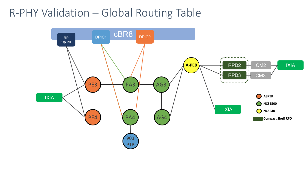
Network Deployment Example
Summary
In this section we will show an example deployments with complete configurations. There are two flavors of deployment covered in this section, the first using the Global Routing Table (GRT) to carry CIN traffic, the second using a L3VPN to carry all CIN traffic. The recommended design option for those building a converged access and aggregation network is to utilize a L3VPN to carry CIN traffic. In both designs we will enable Segment Routing to provide 50ms failover across the CIN network.
Network Diagrams
Global Routing Table with DPIC Leaf
L3VPN Collapsed
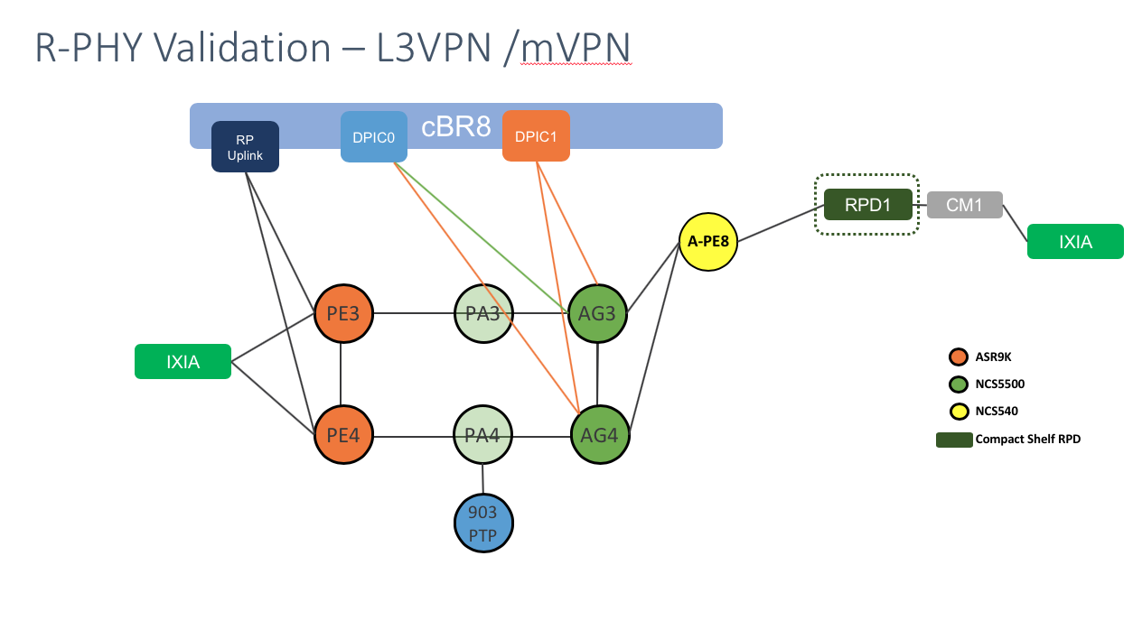
Connectivity Table
| A Node | A Int | Z Node | Z Int | Role |
|---|---|---|---|---|
| PE4 | Te0/0/0/19 | CBR8 | Te4/1/6 | SUP Uplink |
| PE3 | Te0/0/0/19 | CBR8 | Te4/1/5 | SUP Uplink |
| PA3 | Te0/0/0/25 | CBR8 | Te0/1/0 | GRT DPIC to CIN Secondary Active |
| PA3 | Te0/0/0/26 | CBR8 | Te1/1/1 | GRT DPIC to CIN Primary Standby |
| PA3 | BE321 | PE3 | BE321 | Core |
| PA3 | BE421 | PE4 | BE421 | Core |
| PA3 | Te0/0/0/21 | AG3 | Te0/0/0/20 | Core |
| PA3 | Te0/0/0/20 | AG4 | Te0/0/0/21 | Core |
| PA4 | Te0/0/0/25 | CBR8 | Te0/1/1 | GRT DPIC to CIN Secondary Standby |
| PA4 | Te0/0/0/26 | CBR8 | Te1/1/0 | GRT DPIC to CIN Primary Active |
| PA4 | Te0/0/0/5 | TGM-903 | Te0/3/2 | CIN to PTP GM |
| PA4 | BE322 | PE3 | BE322 | Core |
| PA4 | BE422 | PE4 | BE422 | Core |
| PA4 | Te0/0/0/21 | AG3 | Te0/0/0/21 | Core |
| PA4 | Te0/0/0/20 | AG4 | Te0/0/0/20 | Core |
| AG3 | Hu0/0/1/0 | Ag4 | Hu0/0/1/1 | Core |
| AG3 | Te0/0/0/30 | A-PE8 | Te0/0/0/6 | Core (RPD leaf) |
| AG3 | Te0/0/0/25 | CBR8 | Te0/1/2 | L3VPN DPIC to CIN Secondary Active |
| AG3 | Te0/0/0/26 | CBR8 | Te1/1/3 | L3VPN DPIC to CIN Primary Standby |
| AG4 | Te0/0/0/30 | A-PE8 | Te0/0/0/7 | Core (RPD leaf) |
| AG4 | Te0/0/0/25 | CBR8 | Te0/1/3 | L3VPN DPIC to CIN Secondary Standby |
| AG4 | Te0/0/0/26 | CBR8 | Te1/1/2 | L3VPN DPIC to CIN Primary Active |
| A-PE8 | Te0/0/0/15 | RPD0 | Eth0 | RPD |
| A-PE8 | Te0/0/0/16 | RPD1 | Eth0 | RPD |
| A-PE8 | Te0/0/0/17 | RPD2 | Eth0 | RPD |
Consistent Configuration across GRT and L3VPN Designs
PE4 Configuration
PE4 connects to the uplink interfaces on the cBR-8 SUP-250 supervisor module. Its configuration is the same across both designs.
PE4 to Core Sample Interface Configuration
interface Bundle-Ether34
 bfd mode ietf
 bfd address-family ipv4 timers start 180
 bfd address-family ipv4 multiplier 3
 bfd address-family ipv4 destination 10.3.4.0
 bfd address-family ipv4 fast-detect
 bfd address-family ipv4 minimum-interval 50
 mtu 9216
 service-policy input core-ingress-classifier-9k
 service-policy output core-egress-queuing-9k
 ipv4 address 10.3.4.1 255.255.255.254
 ipv4 unreachables disable
 ipv6 address 2405:10:3:4::1/127
 bundle minimum-active links 1
 load-interval 30
 dampening
!
IS-IS Configuration
key chain ISIS-CBR
 key 1
  accept-lifetime 00:00:00 january 01 2018 infinite
  key-string password 08285F471A09040401
  send-lifetime 00:00:00 january 01 2018 infinite
  cryptographic-algorithm HMAC-MD5
 !
!
router isis ACCESS
 set-overload-bit on-startup 360
 is-type level-2-only
 net 49.0001.0102.0000.0004.00
 segment-routing global-block 32000 64000
 nsr
 nsf cisco
 log adjacency changes
 lsp-gen-interval maximum-wait 5000 initial-wait 50 secondary-wait 200
 lsp-refresh-interval 65000
 max-lsp-lifetime 65535
 address-family ipv4 unicast
  metric-style wide
  mpls traffic-eng level-2-only
  mpls traffic-eng router-id Loopback0
  spf-interval maximum-wait 5000 initial-wait 50 secondary-wait 200
  segment-routing mpls
  spf prefix-priority critical tag 5000
  spf prefix-priority high tag 1000
 !
 address-family ipv6 unicast
  metric-style wide
 !
 interface TenGigE0/0/0/19
  circuit-type level-2-only
  point-to-point
  hello-password keychain ISIS-CBR
  address-family ipv4 unicast
   fast-reroute per-prefix
   fast-reroute per-prefix ti-lfa
   metric 100
  !
  address-family ipv6 unicast
   fast-reroute per-prefix
   fast-reroute per-prefix ti-lfa
   metric 100
  !
 !
!
PE4 Multicast and PIM Configuration
In IOS-XR multicast must be enabled on all participating interfaces for IPv4 and IPv6. It is easiest to enable multicast on all interfaces with the “interface all enable” command. PIM should be enabled for IPv4 and IPv6 on all core interfaces as well as the interface to the cBR8 if the cBR8 is acting as a video core.
multicast-routing
 address-family ipv4
  mdt source Loopback0
  rate-per-route
  interface all enable
  accounting per-prefix
 !
 address-family ipv6
  rate-per-route
  interface all enable
  accounting per-prefix
 !
!
router pim
 address-family ipv4
  interface Loopback0
   enable
  !
  interface Bundle-Ether421
   enable
  !
  interface Bundle-Ether422
   enable
  !
  interface TenGigE0/0/0/19
   enable
 address-family ipv6
  interface Loopback0
   enable
  !
  interface Bundle-Ether421
   enable
  !
  interface Bundle-Ether422
   enable
  !
  interface TenGigE0/0/0/19
   enable
PE4 BGP Configuration to CBR8
router bgp 100
 nsr
 bgp router-id 100.0.0.4
 bgp graceful-restart
 ibgp policy out enforce-modifications
 address-family ipv4 unicast
 !
 address-family ipv6 unicast
 !
 neighbor 1.0.0.13
  remote-as 100
  update-source Loopback0
  address-family ipv4 unicast
  !
 !
 neighbor 2001:1::13
  remote-as 100
  update-source Loopback0
  address-family ipv6 unicast
  !
 !
!
cBR-8 Configuration
The cBR-8 configuration will remain the same across each design option.
cBR-8 Line Card Redundancy Configuration
redundancy
 mode sso
 linecard-group 0 internal-switch
  class 1:N
  member slot 1 primary
  member slot 0 secondary
  no revertive
cBR-8 Link HA Configuration
cable rphy link redundancy cold
cBR-8 DPIC and DPIC Routing Configuration
Each DPIC interface is placed in a VRF with associated default routes pointing to the CIN device as its gateway. This configuration ensures traffic destined for the DPIC IP address will only ingress the DPIC interface and not the SUP interface.
vrf definition lc0_p0
 !
 address-family ipv4
 exit-address-family
 !
 address-family ipv6
 exit-address-family
!
!
interface TenGigabitEthernet0/1/0
 description "Connected to PA4 TenGigE0/0/0/25"
 vrf forwarding lc0_p0
 ip address 3.3.9.100 255.255.255.0
 logging event link-status
 cdp enable
 ipv6 address 2001:3:3:9::100/64
 ipv6 enable
!
ip route vrf lc0_p0 0.0.0.0 0.0.0.0 3.3.9.101
!
ipv6 route vrf lc0_p0 ::/0 2001:4:4:9::101
!
vrf definition lc0_p1
 !
 address-family ipv4
 exit-address-family
 !
 address-family ipv6
 exit-address-family
!
!
interface TenGigabitEthernet0/1/2
 description "Connected to AG3 TenGigE0/0/0/25"
 vrf forwarding lc0_p1
 ip address 5.5.9.100 255.255.255.0
 logging event link-status
 cdp enable
 ipv6 address 2001:5:5:9::100/64
 ipv6 enable
!
ip route vrf lc0_p1 0.0.0.0 0.0.0.0 5.5.9.101
!
ipv6 route vrf lc0_p1 ::/0 2001:5:5:9::101
!
vrf definition lc1_p0
 !
 address-family ipv4
 exit-address-family
 !
 address-family ipv6
 exit-address-family
!
!
interface TenGigabitEthernet1/1/0
 description "Connected to PA4 TenGigE0/0/0/25"
 vrf forwarding lc1_p0
 ip address 4.4.9.100 255.255.255.0
 logging event link-status
 load-interval 30
 cdp enable
 ipv6 address 2001:4:4:9::100/64
 ipv6 enable
!
ip route vrf lc1_p0 0.0.0.0 0.0.0.0 4.4.9.101
!
ipv6 route vrf lc1_p0 ::/0 2001:4:4:9::101
!
vrf definition lc1_p1
 !
 address-family ipv4
 exit-address-family
 !
 address-family ipv6
 exit-address-family
!
!
interface TenGigabitEthernet1/1/2
 description "Connected to AG3 TenGigE0/0/0/25"
 vrf forwarding lc1_p1
 ip address 6.6.9.100 255.255.255.0
 logging event link-status
 cdp enable
 ipv6 address 2001:6:6:9::100/64
 ipv6 enable
!
ip route vrf lc1_p1 0.0.0.0 0.0.0.0 6.6.9.101
!
ipv6 route vrf lc1_p1 ::/0 2001:6:6:9::101
cBR-8 SUP Routing
In this example we will utilize IS-IS between the cBR-8 and provider network, and utilize BGP to advertise subscriber and cable modem address space to the rest of the network.
IS-IS Configuration
key chain ISIS-KEYCHAIN
 key 0
  key-string isispass
   accept-lifetime 00:00:00 Jan 1 2018 infinite
   send-lifetime 00:00:00 Jan 1 2018 infinite
   cryptographic-algorithm md5
   !
  !
!
router isis access
 net 49.0001.0010.0000.0013.00
 is-type level-2-only
 router-id Loopback0
 metric-style wide
 log-adjacency-changes
 !
 address-family ipv6
  multi-topology
 exit-address-family
!
interface Loopback0
 ip address 1.0.0.13 255.255.255.255
 ip router isis access
 isis circuit-type level-2-only
end
!
interface TenGigabitEthernet4/1/6
 description "Connected to PE4  TenGigE 0/0/0/19"
 ip address 4.1.6.1 255.255.255.0
 ip router isis access
 load-interval 30
 cdp enable
 ipv6 address 2001:4:1:6::1/64
 ipv6 router isis access
 !! mpls ip optional for LDP enabled CMTS
 mpls ip
 isis circuit-type level-2-only
 isis network point-to-point
 isis authentication mode md5
 isis authentication key-chain ISIS-KEYCHAIN
 isis csnp-interval 10
 hold-queue 400 in
end
BGP Configuration
router bgp 100
 bgp router-id 1.0.0.13
 bgp log-neighbor-changes
 bgp graceful-restart
 timers bgp 5 60
 neighbor 2001:100::4 remote-as 100
 neighbor 2001:100::4 ha-mode sso
 neighbor 2001:100::4 update-source Loopback0
 neighbor 2001:100::4 ha-mode graceful-restart
 neighbor 100.0.0.4 remote-as 100
 neighbor 100.0.0.4 ha-mode sso
 neighbor 100.0.0.4 update-source Loopback0
 neighbor 100.0.0.4 ha-mode graceful-restart
 !
 address-family ipv4
  redistribute connected
  redistribute static route-map static-route
  no neighbor 2001:100::4 activate
  neighbor 100.0.0.4 activate
  neighbor 100.0.0.4 send-community extended
  neighbor 100.0.0.4 next-hop-self
  neighbor 100.0.0.4 soft-reconfiguration inbound
 exit-address-family
 !
 address-family ipv6
  redistribute connected
  neighbor 2001:100::4 activate
  neighbor 2001:100::4 send-community extended
  neighbor 2001:100::4 next-hop-self
  neighbor 2001:100::4 soft-reconfiguration inbound
 exit-address-family
CIN Core Configuration
Much of the configuration across the IOS-XR CIN nodes is the same with regards to routing. Single examples will be given which can be applied across the specific devices and interfaces in the design.
Network Timing Configuration
See the timing configuration section in this document for standard timing profiles. The following diagram shows the flow of timing end to end across the network.
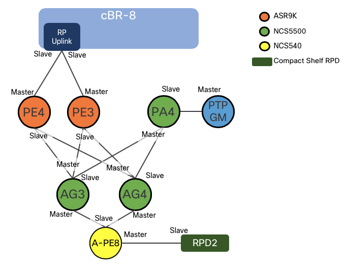
Timing Configuration between PA4 and ASR-903 Grandmaster
The following configuration enabled IPv4 G.8275.2 and SyncE between the Grandmaster to the CIN network
interface TenGigE0/0/0/5
 description Connected to PTP Grandmaster
 ptp
  profile g82752_slave_v4
  transport ipv4
  port state slave-only
  master ipv4 23.23.23.1
  !
 !
 ipv4 address 10.1.15.1 255.255.255.0
 ipv6 nd prefix default no-adv
 ipv6 nd other-config-flag
 ipv6 nd managed-config-flag
 ipv6 address 2001:10:1:15::1/64
 load-interval 30
 frequency synchronization
  selection input
  priority 1
  wait-to-restore 1
 !
!
Physical Interface Configuration for Timing Master
The following is used on core interfaces with downstream slave interfaces
interface TenGigE0/0/0/20
 mtu 9216
 ptp
  profile g82752_master_v4
 !
 service-policy input core-ingress-classifier
 service-policy output core-egress-queuing
 service-policy output core-egress-exp-marking
 ipv4 address 10.22.24.0 255.255.255.254
 ipv4 unreachables disable
 ipv6 address 2405:10:22:24::/127
 load-interval 30
 dampening
!
IS-IS Configuration - PA3, PA4, AG3, AG4, A-PE8
The following IS-IS configuration is used on all CIN IOS-XR nodes. An example is given for a core interface along with the loopback interface with SR enabled. The prefix-sid index of Lo0 must be unique on each node.
router isis ACCESS
 set-overload-bit on-startup 360
 is-type level-2-only
 net 49.0001.0102.0000.0022.00
 segment-routing global-block 32000 64000
 nsr
 nsf cisco
 log adjacency changes
 lsp-gen-interval maximum-wait 5000 initial-wait 50 secondary-wait 200
 lsp-refresh-interval 65000
 max-lsp-lifetime 65535
 address-family ipv4 unicast
  metric-style wide
  microloop avoidance segment-routing
  mpls traffic-eng level-2-only
  mpls traffic-eng router-id Loopback0
  spf-interval maximum-wait 5000 initial-wait 50 secondary-wait 200
  segment-routing mpls
  spf prefix-priority critical tag 5000
  spf prefix-priority high tag 1000
 !
 address-family ipv6 unicast
  metric-style wide
 !
 interface Loopback0
  address-family ipv4 unicast
   prefix-sid index 22
  !
  address-family ipv6 unicast
  !
 !
 interface Bundle-Ether322
  bfd minimum-interval 50
  bfd multiplier 3
  bfd fast-detect ipv4
  bfd fast-detect ipv6
  point-to-point
  hello-password keychain ISIS-KEY
  address-family ipv4 unicast
   fast-reroute per-prefix
   fast-reroute per-prefix ti-lfa
   metric 100
   adjacency-sid absolute 15322 protected
  !
  address-family ipv6 unicast
   fast-reroute per-prefix
   fast-reroute per-prefix ti-lfa
   metric 100
  !
 !
CIN to cBR8 DPIC Configurations
The following gives an example of the configuration between the CIN interface and the DPIC interface on the cBR8 for both global routing table (GRT) and L3VPN deployments. This also includes the routing configuration needed to advertise the DPIC IP address across the CIN for reachability between RPD and DPIC.
CIN to DPIC Global Routing Table
In this use case we are utilizing the IGP, IS-IS for reachability between the RPD and DPIC interface.
PA4 Te0/0/0/26 to cBR8 DPIC Te0/1/1 primary active interface
interface TenGigE0/0/0/26
 description Connected to cbr8 port te0/1/1
 cdp
 service-policy input rpd-dpic-ingress-classifier
 service-policy output rpd-dpic-egress-queuing
 ipv4 address 3.3.9.101 255.255.255.0
 ipv6 address 2001:3:3:9::101/64
 carrier-delay up 150 down 0
 load-interval 30
!
IS-IS Configuration
router isis ACCESS
 interface TenGigE0/0/0/26
  passive
  address-family ipv4 unicast
  !
  address-family ipv6 unicast
  !
 !
!
CIN to DPIC L3VPN
The L3VPN configuration requires additional configuration for the RPHY VRF as well as BGP configuration to exchange VPNv4 prefixes between the RPD leaf node and the DPIC leaf node. In this use case an external route-reflector is used to exchange routes between all CIN routers.
BGP Configuration
router bgp 100
 nsr
 bgp router-id 100.0.2.4
 bgp graceful-restart
 ibgp policy out enforce-modifications
 address-family vpnv4 unicast
 !
 address-family vpnv6 unicast
 neighbor-group SvRR
  remote-as 100
  update-source Loopback0
  address-family vpnv4 unicast
   soft-reconfiguration inbound always
  !
  address-family vpnv6 unicast
   soft-reconfiguration inbound always
  !
 neighbor 100.0.2.202
  use neighbor-group SvRR
 !
 vrf rphy-vrf
  rd auto
  address-family ipv4 unicast
   label mode per-vrf
   redistribute connected
   redistribute static
  !
  address-family ipv4 mvpn
  !
  address-family ipv6 mvpn
  !
 !
!
VRF Configuration
vrf rphy-vrf
  rd auto
  address-family ipv4 unicast
   label mode per-vrf
   redistribute connected
   redistribute static
  !
  address-family ipv4 mvpn
  !
  address-family ipv6 mvpn
  !
 !
!
AG4 Te0/0/0/26 to cBR8 DPIC Te1/1/2 primary active interface
interface TenGigE0/0/0/26
 description .. Connected to cbr8 port te0/1/3
 cdp
 service-policy input rpd-dpic-ingress-classifier
 service-policy output rpd-dpic-egress-queuing
 vrf rphy-vrf
 ipv4 address 5.5.9.101 255.255.255.0
 ipv6 address 2001:5:5:9::101/64
 ipv6 address 2001:6:6:9::101/64
 load-interval 30
!
CIN to RPD Configuration
This section will highlight configurations used to support the RPD in both GRT and L3VPN configurations, including all relevant protocols.
CIN to RPD Router Timing Configuration
The timing configuration is shared across both GRT and L3VPN configurations.
Global timing configuration
ptp
 clock
  domain 60
  profile g.8275.2 clock-type T-BC
 !
 profile g82752_slave_v4
  transport ipv4
  port state slave-only
  sync frequency 16
  clock operation one-step
  announce interval 1
  unicast-grant invalid-request deny
  delay-request frequency 16
 !
 profile g82752_slave_v6
  transport ipv6
  port state slave-only
  sync frequency 16
  clock operation one-step
  announce interval 1
  unicast-grant invalid-request deny
  delay-request frequency 16
 !
 profile g82752_master_v4
  transport ipv4
  port state master-only
  sync frequency 16
  clock operation one-step
  announce interval 1
  unicast-grant invalid-request deny
  delay-request frequency 16
 !
 profile g82752_master_v6
  transport ipv6
  port state master-only
  sync frequency 16
  clock operation one-step
  announce timeout 10
  announce interval 1
  unicast-grant invalid-request deny
  delay-request frequency 16
 !
 frequency priority 5
 time-of-day priority 5
 log
  servo events
  best-master-clock changes
 !
!
Core-facing (slave) timing configuration
This node has two core-facing interfaced to PA3 and PA4. On interface Te0/0/0/6 to PA3 we will use IPv6 and on Te0/0/0/7 to PA4 we will use IPv4. There is also an example of utilizing a VRF and sub-interface to force traffic into this physical interface. PTP packets must ingress the physical interface to be considered valid. There can be a situation with a dual-homed leaf where traffic to the Te0/0/0/6 interface comes in through the Te0/0/0/7 interface. One way to alleviate the issue is via proper IGP routing configuration, the second to use a local VRF with no reachability except via a single physical interface.
interface TenGigE0/0/0/6
 cdp
 service-policy input core-ingress-classifier
 service-policy output core-egress-queuing
 service-policy output core-egress-exp-marking
 ipv4 address 10.23.253.1 255.255.255.254
 ipv6 address 2405:10:23:253::1/127
 load-interval 30
!
interface TenGigE0/0/0/6.1000
 ptp
  profile g82752_master_v6
  master ipv6 2001:999::
   priority 5
  !
 !
 vrf PTP-test
 ipv4 address 10.1.1.1 255.255.255.254
 ipv6 address 2001:999::1/64
 load-interval 30
 encapsulation dot1q 1000
!
interface TenGigE0/0/0/7
 cdp
 ptp
  profile g82752_slave_v4
  master ipv4 10.24.253.0
  !
  master ipv4 100.100.100.1
   priority 10
  !
 !
 service-policy input core-ingress-classifier
 service-policy output core-egress-queuing
 service-policy output core-egress-exp-marking
 ipv4 address 10.24.253.1 255.255.255.254
 ipv6 address 2405:10:24:253::1/127
 load-interval 30
!
GRT Specific Configuration
DHCP Configuration
dhcp ipv4
 profile rpd-dhcpv4 relay
  helper-address vrf default 4.4.9.100
  helper-address vrf default 10.0.2.3
 !
 inner-cos 5
 outer-cos 5
 interface TenGigE0/0/0/16 relay profile rpd-dhcpv4
 interface TenGigE0/0/0/17 relay profile rpd-dhcpv4
Multicast Routing Configuration
multicast-routing
 address-family ipv4
  interface Loopback0
   enable
  !
  interface TenGigE0/0/0/6
   enable
  !
  interface TenGigE0/0/0/7
   enable
  !
  mdt source Loopback0
  rate-per-route
  interface all enable
  accounting per-prefix
 !
 address-family ipv6
  interface Loopback0
   enable
  !
  interface TenGigE0/0/0/6
   enable
  !
  interface TenGigE0/0/0/7
   enable
  !
  rate-per-route
  interface all enable
  accounting per-prefix
 !
PIM Configuration
router pim
 address-family ipv4
  interface Loopback0
   enable
  !
  interface TenGigE0/0/0/6
   enable
  !
  interface TenGigE0/0/0/7
   enable
  !
IGMP/MLD and Snooping Configuration
router mld
 interface BVI100
  version 2
 !
!
router igmp
 interface BVI100
  version 3
 !
!
mld snooping profile mld-snoop-1
!
igmp snooping profile igmp-snoop-1
DHCP Configuration
dhcp ipv4
 vrf rphy-vrf relay profile rpd-dhcpv4-vrf
 profile rpd-dhcpv4 relay
  helper-address vrf default 4.4.9.100
  helper-address vrf default 10.0.2.3
 !
 profile rpd-dhcpv4-vrf relay
  helper-address vrf rphy-vrf 10.0.2.3
  relay information option allow-untrusted
 !
 inner-cos 5
 outer-cos 5
 interface BVI100 relay profile rpd-dhcpv4
!
Physical Interface Configuration
In this configuration we are using a BVI to aggregate RPDs into a single L3 IP subnet, so note the “l2transport” keyword which places the RPD port in L2 mode
interface TenGigE0/0/0/16
 description .. to RPD1
 load-interval 30
 l2transport
L2VPN Bridge Domain Configuration
In IOS-XR all L2 configuration is done under the L2VPN context.
l2vpn
 bridge group rpd
  bridge-domain rpd-1
   mld snooping profile mld-snoop-1
   igmp snooping profile igmp-snoop-1
   interface TenGigE0/0/0/16
   !
   interface TenGigE0/0/0/17
   !
   routed interface BVI100
   !
  !
IRB/BRI Logical Interface Configuration
The BVI acts as the gateway interface for all RPDs placed within the same bridge-domain with BVI100 assigned as its routed interface. The command “local-proxy-arp” requires all traffic to bridge through the L3 interface, otherwise ARP traffic is b roadcast between all connected ports.
interface BVI100
 description ... to downstream RPD
 service-policy input rpd-dpic-ingress-classifier
 ipv4 address 192.168.2.1 255.255.255.0
 local-proxy-arp
 ipv6 nd suppress-ra
 ipv6 nd other-config-flag
 ipv6 nd managed-config-flag
 ipv6 address 2001:192:168:2::1/64
 ipv6 enable
!
IS-IS Routing Configuration for RPD Interface
Communication between DPIC interface and RPD is realized by advertising the BVI interface throughout the IS-IS domain. We utilize the “passive” option to advertise the interface with it participating in IS-IS itself.
router isis ACCESS
  interface BVI100
    passive
    address-family ipv4 unicast
    !
    address-family ipv6 unicast
L3VPN Configuration
The L3VPN configuration is similar to the GRT configuration with the following major differences:
- Multicast traffic is carried using Label Switched Multicast with mLDP and using the NG-MVPN BGP control-plane. This is known as multicast profile 14.
- Like the DPIC configuration, the RPD interface is advertised using MP-BGP using the VPNv4/VPNv6 address families
- Changes are needed to enable multicast, IGMP/MLD, and DHCP for VRF awareness
- In the following configuration, the RPD is connected to the router via a point-to-point L3 interface, no bridge-domain is utilized. There is no restriction using L3VPN with BVI interfaces.
VRF Configuration
 vrf rphy-vrf
  rd auto
  address-family ipv4 unicast
   label mode per-ce
   redistribute connected
   redistribute static
  !
  address-family ipv6 unicast
   label mode per-ce
   redistribute connected
   redistribute static
  !
  address-family ipv4 mvpn
  !
  address-family ipv6 mvpn
  !
 !
DHCP Configuration
dhcp ipv4
 vrf rphy-vrf relay profile rpd-dhcpv4-vrf
 profile rpd-dhcpv4-vrf relay
  helper-address vrf rphy-vrf 10.0.2.3
  relay information option allow-untrusted
 !
 inner-cos 5
 outer-cos 5
 interface TenGigE0/0/0/15 relay profile rpd-dhcpv4-vrf
!
MPLS mLDP Configuration
LDP is configured with mLDP-only on the two core interfaces to PA3/PA4.
mpls ldp
 capabilities sac mldp-only
 mldp
  address-family ipv4
   make-before-break delay 30
   forwarding recursive
   recursive-fec
  !
 !
 router-id 100.0.2.53
 session protection
 address-family ipv4
 !
 interface TenGigE0/0/0/6
 !
 interface TenGigE0/0/0/7
 !
!
BGP Configuration
BGP is configured for two purposes. Distribute VPNv4/VPNv6 across the network for RPD to DPIC connectivity, and to exchange multicast routes between source and receiver nodes to build dynamic mLDP P2MP trees. Again, a cetnralized route reflector is used between all CIN elements.
router bgp 100
 nsr
 bgp router-id 100.0.2.53
 bgp graceful-restart
 ibgp policy out enforce-modifications
 address-family vpnv4 unicast
 !
 address-family vpnv6 unicast
 !
 address-family ipv4 mvpn
 !
 address-family ipv6 mvpn
 !
 neighbor-group SvRR
  remote-as 100
  update-source Loopback0
  address-family vpnv4 unicast
   soft-reconfiguration inbound always
  !
  address-family vpnv6 unicast
   soft-reconfiguration inbound always
  !
  address-family ipv4 mvpn
   soft-reconfiguration inbound always
  !
  address-family ipv6 mvpn
   soft-reconfiguration inbound always
  !
 !
 neighbor 100.0.2.202
  use neighbor-group SvRR
 !
 vrf rphy-vrf
  rd auto
  address-family ipv4 unicast
   label mode per-ce
   redistribute connected
   redistribute static
  !
  address-family ipv4 mvpn
  !
  address-family ipv6 mvpn
  !
Multicast Configuration
multicast-routing
 address-family ipv4
  interface Loopback0
   enable
   !
  !
 !
 vrf rphy-vrf
  address-family ipv4
   mdt source Loopback0
   rate-per-route
   interface all enable
   accounting per-prefix
   bgp auto-discovery mldp
   !
   mdt partitioned mldp ipv4 p2mp
  !
 !
PIM Configuration
router pim
 vrf rphy-vrf
  address-family ipv4
   rpf topology route-policy mldp-partitioned-p2mp
   mdt c-multicast-routing bgp
   !
  !
MLD and PIM Configuration
router mld
 vrf rphy-vrf
  interface TenGigE0/0/0/15
   version 2
  !
 !
!
router igmp
 vrf rphy-vrf
  interface BVI101
   version 3
  !
  interface TenGigE0/0/0/15
  !
 !
!
Router to RPD Physical Interface Configuration
interface TenGigE0/0/0/15
 description .. to RPD0
 ptp
  profile g82752_master_v4
 !
 service-policy input rpd-dpic-ingress-classifier
 service-policy output rpd-dpic-egress-queuing
 vrf rphy-vrf
 ipv4 address 192.168.3.1 255.255.255.0
 load-interval 30
!
Leave a Comment