
Core Fabric Design
Key Drivers
The Core Fabric Design represents an evolution in backbone core networks. There are several factors driving this evolution.
Scale
Driven by broadband speed improvements, the rise of video and the advent of 5G, global IP traffic is expected to triple in the next five years. However, not all of that traffic is destined to cross the traditional backbone core. Already, the majority of Internet traffic is delivered by Content Delivery Networks (CDNs) (e.g. Google, Apple, Amazon, Microsoft, Facebook, Netflix) on private CDN networks. CDNs are bringing content closer to the end user, delivering content into regional networks and, increasing, directly to the metro. With metro-based peering and caching, some Service Providers are already serving 70% of externally-sourced traffic from peering points or CDNs from within their major metros.
The change in traffic patterns are significant in core design for several reasons. First, the traditional Service Provider backbone network will grow more slowly, moderating the rapidly increasing scale requirements that have characterized core design for the last 15 years. Second, the connectivity requirements of different core functions (e.g. connecting to other core routers over long-haul links, connecting to metro PE and/or aggregation routers, connecting to peering) may scale differently. Third, private backbones will continue to grow as CDN operators build out capacity to deliver their content to regional and metro networks. Lastly, the metro core will evolve to meet the scale demands of the metro-delivered content.
Network Availability
Network availability has always been a key design goal of core networks. The industry’s attempt to provide network resilience through device-level redundancy mechanisms (NSF, NSR, ISSU, etc) is reaching the limits of effectiveness. While the typical 1+1 redundancy model provides “good enough” availability for many operators, others are looking for new ways to increase availability, whether through new topologies or simplified protocols. Instead of building ever-larger and more complex devices to connect expensive WAN links, core networks can leverage horizontal, DC-inspired fabrics to scale out while increasing availability. Because traffic is spread across more, smaller boxes in a fabric, the loss of any single device has a much smaller blast radius. Instead of using a complex and stateful protocol like RSVP-TE for Fast Re-Route (FRR), customers can use the simpler, built-in mechanisms of Segment Routing Transport Independent Loop Free Alternative (TI-LFA).
Cost
For many operators, bandwidth scales faster than revenue, so the core must be cost effective to build and operate. The lower cost of 100GE routers and line cards, fueled by the speed and power optimization of new silicon offerings, have accelerated the adoption of 100GE in high end routing. Today, simple, high-density routers can provide up to 57.6 Tbps in a single chassis at a fraction of the cost per 100 GigabitEthernet interface as on previous generations of silicon/network-processors. The increase in capacity enables providers to consider reducing or eliminating complex features (like QoS) that were developed to manage limited capacity. It is also possible to build fabrics out of smaller, simpler systems to achieve capex flexibility: you add more capacity when you need it. To scale the cost of operations, automation is the only answer.
Automation
Manual operations are expensive and don’t scale. The next-gen core design must be fully automatable, starting with data models and APIs in the network routers. Additional tools can provide layers of abstraction that make it easier for operator’s OSS/BSS to quickly translate business intent to network operation.
Network Simplification
Simplicity scales; complexity does not. By reducing the amount of state and number of protocols in the core, operators can deploy networks that are easier to scale and simpler to operate. Simplification also enables automation: the simpler and more uniform the design, the easier it is to automate. Optimized control-plane elements and feature sets enhance stability and availability. Dedicating nodes to specific functions of the network also helps isolate the rest of the network from malicious behavior, defects, or instability.
High-Level Design
The Core design incorporates high-density routers and a small, recommended feature set delivered through IOS-XR to solve the needs of service providers. The Core design also includes ways to monitor the health and operational status of the core and assist providers in migration. All Cisco SP Validated designs are both feature tested and validated as a complete design.
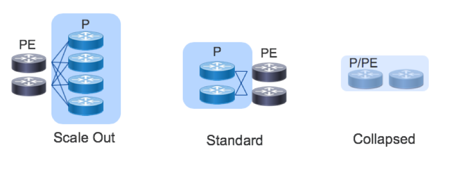
Topology: Scale Out and Scale Up
The gold standard of SP core deployments in the classic two-node setup, where two chassis connect to each other and the Metro or Peering elements in a redundant fashion. In very small deployments, the P and PE functions may be collapsed into a single device.
In such a setup, scale is achieved by “scaling up” (aka vertical scaling). In a scale-up model, you add more capacity by replacing small chassis with large chassis or adding higher-density line cards to modular chassis.
The ultimate “scale up” topology is a multi-chassis cluster that can add entire line card chassis to support more connections.
While scale-up systems are suitable for many applications, failures and operational issues can be difficult to troubleshoot and repair. Moreover, when there is only one or two large boxes in a role, the “blast radius” of an outage can be substantial. The large blast radius means that scale-out systems require lengthy planning and timeframes for system upgrades. To address these concerns, the core design offers a horizontally scalable option with the goal of improving availability while simplifying failure types to more deterministic interface or node failures. Horizontal scaling is sometimes referred to as “scaling out.” It also enables throughput scaling beyond what is possible with today’s largest chassis.
Scale out can be as simple as adding more standalone boxes in parallel (e.g. 4 or 8 smaller routers instead of the traditional 2).
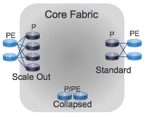
Having more, smaller routers increases the amount of connectivity for the metro and peering while reducing the blast radius of a single failure. A single router can fail (or be taken out of service for upgrade) with a much smaller impact on the network. While scale out results in more boxes to manage, automation can be used to reduce complexity and ensure consistency across the network.
The reference topology for the Core design supports the standard 1+1 deployment, the collapsed P/PE deployment for small deployments, and a simple scale-out.
Platforms
The Cisco NCS5500 platform is ideal for backbone core routing, given its high-density, large RIB and FIB scale, buffer capacity, and IOS-XR software feature set. The NCS5500 is also space and power efficient with 36x100GE in a 1RU fixed form factor or single modular line card.
A minimal core can provide 36x100GE, 144x10GE, or a mix of non-blocking connections with full resiliency in 4RU. The fabric can also scale to support 10s of terabits of capacity in a single rack for large core deployments. Fixed chassis are ideal for incrementally building a fabric: the NCS NC55-36X100GE-A-S and NC55A1-24H are efficient high density building blocks which can be rapidly deployed as needed without installing a large footprint of devices day one. Deployments needing more capacity or interface flexibility can utilize the NCS5504 4-slot, NCS5508 8-slot or NCS5516 16-slot modular chassis. If the network has a need for multicast or other advanced features, the ASR9000 family or other node can be incorporated into the design.
All NCS5500 routers also contain powerful Route Processors to unlock telemetry and programmability. The fixed chassis contain 1.6Ghz 8-core processors and 32GB of RAM. The latest NC55-RP-E for the modular NCS5500 chassis has a 1.9Ghz 6-core processor and 32G of RAM.
Control-Plane
The core design introduces a simplified control-plane built on Segment Routing that supports scale and efficiency in transport.
Segment Routing extensions advertises MPLS Labels for devices (Prefix-SIDs) and links (Adjacency-SIDs) as part of the IGP which enables a simplified forwarding plane, eliminates the need for LDP and RSVP, and increases scale and stability by eliminating the heavy amount of control plane state the router must manage while maintaining an RSVP-TE mesh. With Segment Routing, traffic can be source-routed to a node SID or an anycast SID representing a set of nodes. ECMP behavior is preserved at each point in the network and redundancy is simplified.
Because each node in the domain calculates a primary and backup path, Segment Routing automatically provides a Fast ReRoute (FRR) mechanism using Topology Independent Loop Free Alternative (TI-LFA). TI-LFA requires no additional signaling protocol and typically provides convergence times below 50 ms with 100% link and node protection. More information on Segment Routing technology and its future evolution can be found at http://segment-routing.net
Telemetry
The core design uses the rich telemetry available in IOS-XR and the NCS5500 platform to enable an unprecedented level of insight into network and device behavior. The Cisco SP Validated Core leverages Model-Driven Telemetry and NETCONF along with both standard and native YANG models for metric statistics collection. Telemetry configuration and applicable sensor paths have been identified to assist providers in knowing what to monitor and how to monitor it. Through streaming data mechanisms such as Model-Driven Telemetry, providers can extract data useful for operations, capacity planning, security, and many other use cases.
The core also fully supports traditional collections methods such as SNMP, and NETCONF using YANG models to integrate with legacy systems.
Other telemetry mechanisms such as Netflow and BMP have limited applicability in the Core and are not in the scope of this design.
Automation
NETCONF and YANG using OpenConfig and native IOS-XR data models are used to help automate configuration and validation. Cisco has developed Network Service Orchestrator (NSO) services to help automate common Segment Routing migration tasks using NETCONF NEDs.
Validated Design
The control, management, and forwarding planes in this design have undergone validation testing to ensure individual design features work as intended and the peering fabric as a whole performs without fault. Validation is done exceeding real-world scaling requirements to ensure the design fulfills its rule in existing networks with room for future growth.
Use Cases
LDP to SR Core Migration
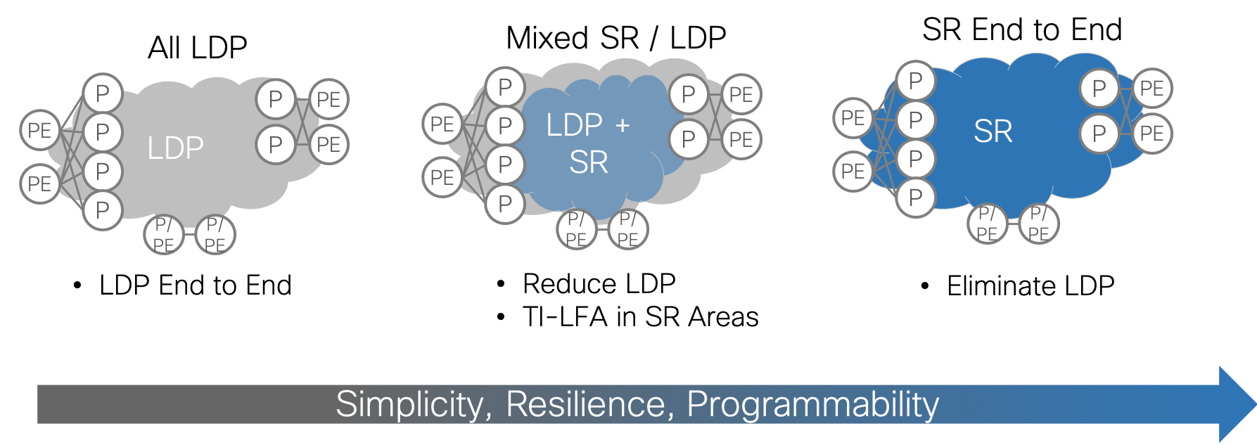
Many customers run LDP in the core today. To simplify and scale, one of the most important steps is to migrate from LDP to Segment Routing (SR). The benefits of SR are clear: protocol simplification, simplified resiliency, and multi-domain programmability. What is less clear is how to accomplish the migration. Greenfield networks are rare and pockets of LDP will continue to exist in most networks for a long time to come. Cisco SP Validated Core approaches SR migration in a series of steps that are intended to maintain existing functionality while gradually enabling SR and transitioning traffic to SR LSPs. Each migration step has an NSO service profile associated with it to ensure a consistent, best-practice implementation.
While end-to-end SR is the goal, it may not always be possible at a given point in time. Customers may be looking to refresh the P routers and not the PE routers. Legacy PE routers may not support SR even if new PEs do. Therefore, it is important to find value at each step of the migration and maintain support for non-SR PEs through the process.
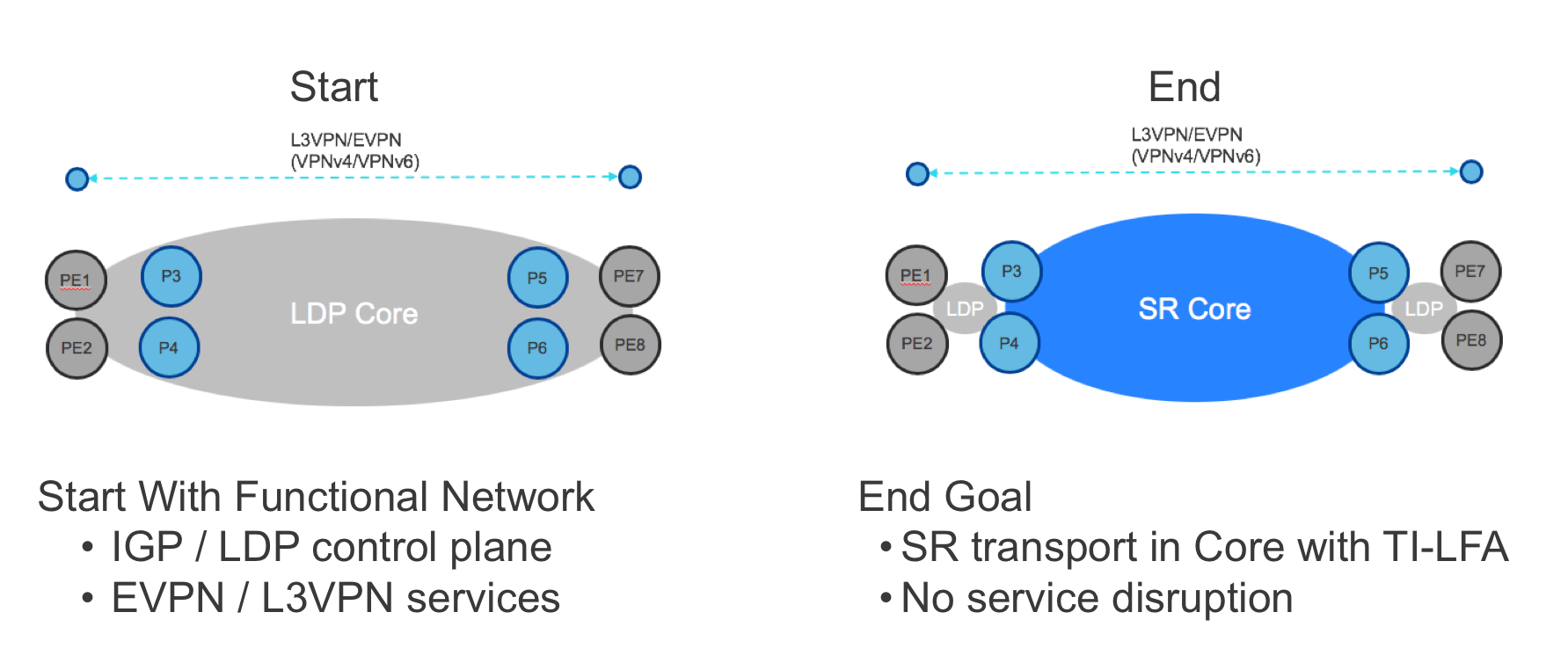
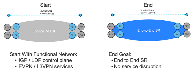
Starting Point
This migration use case assumes that the Core is already configured as a functional MPLS network with the following characteristics:
- Single instance of ISIS as the IGP
- LDP for label distribution
- BGP-free core
- Working L2/L3 VPN services from PE to PE using BGP
The goal of the migration is to preserve existing services while migrating the core in an incremental, validated, step-by-step fashion.
Step 1: Enable SR
In the first step of migration, SR is enabled on the P routers using CLI or (preferably) NETCONF/YANG. The latter can be orchestrated using the NSO sr service, ensuring that:
- Every router uses the same ISIS instance, loopback interface and global block of labels.
- Every router is assigned a unique prefix-SID from the global block of labels.
- The SR service can be rolled out across multiple devices in a transactional fashion and seamlessly rolled back if needed.
Deploying SR by itself in this way will not impact the forwarding plane in any way: the P routers will continue to use LDP labels to forward traffic until 1) the PE routers use SR or 2) LDP is disabled in the core. Nevertheless, it is possible to deeply validate the operation of SR even while still using LDP forwarding. The following validations can be performed via CLI or (preferably) a model-based query method such as NETCONF/YANG, YDK, or NSO’s live-status capability:
- Each router successfully assigns the desired block from the label database.
- The IGP is advertising SR labels for every SR-enabled router’s loopback.
- Each router is programming the SR labels in the RIB and FIB.
- Traffic is forwarded using LDP labels.
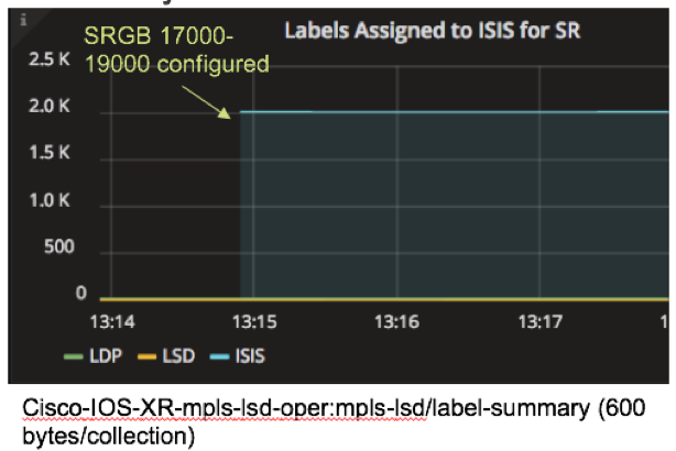
YANG-modeled operational data can also be streamed using model-driven telemetry. In this example, model driven telemetry is streaming Cisco-IOS-XR-mpls-lsd-oper:mpls-lsd/label-summary data, making it easy to see that the number of labels assigned to ISIS jumps to 2000 when the SR global block of labels is configured.
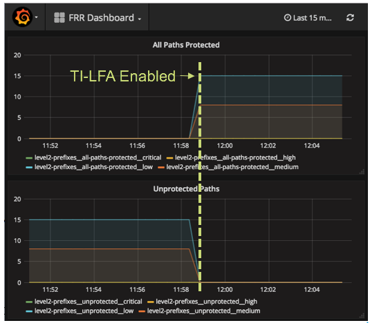
Step 2: Enable TI-LFA
In this step, TI-LFA is configured for link protection. The NSO ti-lfa service leverages the same resource pools as the “sr” service and greatly simplifies the configuration process by enabling TI-LFA under every non-loopback interface in the given ISIS instance.
As soon as it is enabled, TI-LFA protects IP, LDP and SR traffic. This means that all traffic in the Core now has the benefit of sub-50 millisecond convergence times without complicated RSVP-TE tunnels. Network availability is improved even before the primary forwarding plane is switched to SR.
The operation of TI-LFA should be validated to ensure that all paths are protected. YANG models can be used to retrieve or stream the relevant operational data.
In the example below, model driven telemetry is streaming Cisco-IOS-XR-clns-isis-oper:isis/instances/instance/topologies/topology/frr-summary, making it easy to see that the number of protected paths increases when TI-LFA is configured.
Step 3: Enable Mapping Servers
In this step, mapping servers are configured to provide SR labels for LDP-only endpoints, specifically the loopback addresses of non-SR PEs. Mapping servers can be configured anywhere in the network. At least two mapping servers should be configured for redundancy.
This step can be achieved through CLI or NETCONF/YANG. To automate the process, use the NSO sr-ms service which leverages the same infrastructure as the “sr” services to simplify and ensure consistency in the configuration process.
At the end of this step, the P routers will have SR labels for all P and PE routers. However, the VPN services will still use the LDP LSPs from end-to-end since the non-SR PE routers still initiate the service with an LDP label.
To validate the Mapping Server configuration, check that the non-SR endpoint addresses are represented by labels in the IGP, RIB and FIB as in Step 1. In addition, specific prefixes can be queried on the mapping server.
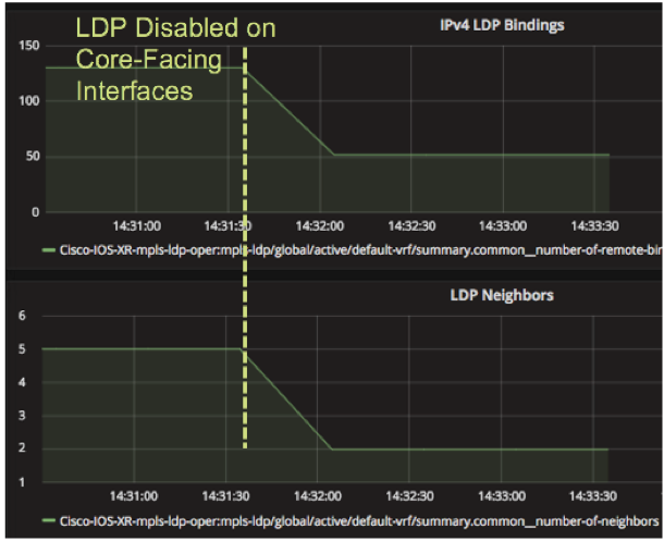
Step 4: Protocol Simplification
Once the P routers are fully configured for SR, LDP can optionally be disabled on a link-by-link basis for every link pair that has SR enabled on each end. When this step is accomplished, the P routers will use the SR label for the path across the core. The benefit of this step is fewer protocols to maintain and troubleshoot in the core. There should be no impact to the VPN services when the transition is made.
The disable-ldp service can be used in NSO to orchestrate this step on a link-by-link basis. Telemetry can be used to track the impact of disabling LDP on core-facing interfaces using the Cisco-IOS-XR-mpls-ldp-oper:mpls-ldp/global/active/default-vrf/summary path as shown below.
Some customers may choose not to disable LDP in the core until all PE routers have been migrated to SR as well, creating an end-to-end S deployment. In that case, LDP provides the primary forwarding path while SR provides TI-LFA until the rest of the network is ready to switch to SR.
LDP over RSVP-TE to SR Migration
Customers with LDP cores who need fast-recovery in the event of a failure often deploy RSVP-TE for fast reroute (FRR). A common design pattern is to create a mesh of TE tunnels among P routers and tunnel LDP over it. A P router mesh does not provide an end-to-end solution for fast-recovery but it is more scalable than a PE router mesh. But even a P router mesh can require a substantial amount of configuration as the number of tunnels scales as the square of the number of P routers. Optimizations such as auto-tunnel mesh groups can be used to simplify the configuration. Even so, the amount of RSVP state that the network is required to maintain even for a P router mesh is substantial.
Migrating from LDP over RSVP to Segment Routing in the Core provides an exceptionally good value proposition. Because TI-LFA provides fast-route for all traffic, customers can remove their RSVP-TE FRR configuration and all the associated complexity and state while maintaining sub 50-milisecond convergence. Moreover, SR with TI-LFA enables 100% coverage and micro-loop avoidance.
To achieve this use case, follow the same steps as above, disabling RSVP-TE in the core when all the core routers have been enabled for SR.
LDP to SR End-to-End Migration
In the case where the PE devices are SR-capable, the previous use cases can be extended to run SR end-to-end. This can be done incrementally on a PE by PE basis until all PEs are migrated. The benefits of this additional step include end-to-end TI-LFA and further reduction in LDP maintenance. In addition, once end-to-end SR transport has been implemented, the Core is ready to integrate with other SR designs in the Metro and Peering.
The goal of this use case is the same as before: enable full or partial migration of the PE devices without service disruption.
Step 1: Enable SR on the PEs
Enabling SR on the PEs will happen in two stages. First, SR will be enabled but not preferred. This means that the PEs will learn SR labels for all the endpoints in the network but still initiate the VPN services using LDP labels. This step can be accomplished using the same NSO “sr” service as the P routers in the previous use case and validation follows the same steps for the PE routers.
Step 2: Enable SR on the PEs
Finally, the PEs will be configured for “sr-prefer” one by one, slowly transitioning the traffic to end-to-end SR. The NSO sr service includes an option for sr-prefer in the “sr” service. LDP can then be disabled on the PEs as well.
Low Level Design
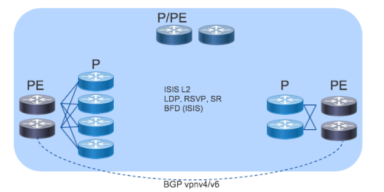
Validation Topology
The Core validation topology included three types of core sites: a standard 2 P x 2 PE design, a collapsed 2xP/PE and a scale out design with 4xP routers.
Hardware Detail
The NCS5500 family of routers provide high density, ideal buffer sizes, and environmental efficiency for core routing use cases. All of the following platforms can be used in the Core designs above. Further detailed information on each platform can be found at https://www.cisco.com/c/en/us/products/routers/network-convergence-system-5500-series/index.html.
The 55A1-36H is a second generation 1RU NCS5500 fixed platform with 36 100GE QSFP28 ports operating at line rate. All the ports can support 100GE and 40GE optics as well as 25G to 10GE breakout. It also contains a powerful multi-core route processor with 64GB of RAM and an on-board 64GB SSD. Its high density, efficiency, and buffering capability make it ideal in 10GE or 100GE deployments.
The NCS-55A1-24H is a second generation 1RU NCS5500 fixed platform with 24 100GE QSFP28 ports. It uses two 900GB NPUs, with 12X100GE ports connected to each NPU.
NCS 5504 and 5508 Modular Chassis and NC55-36X100G line card
Large deployments or those needing interface flexibility such as IPoDWDM connectivity can use the modular NCS5500 series chassis.
Control Plane
The Core uses a single instance of ISIS that encompasses all PE and P devices with BFD for fault protection. BGP VPNv4/v6 runs between the PEs to provide services. For label distribution, LDP and/or RSVP-TE runs between the P devices with LDP between P and PE devices with the ultimate goal of transitioning all label distribution to Segment Routing.
Configuration
The following configuration guidelines will step through the major components of the device and protocol configuration specific to SR migration in the Core. Only the net-new configuration for SR is included. It is assumed that an ISIS instance is fully configured and operational across all nodes, as well as LDP.
CLI examples are given here for readability. The equivalent NETCONF/YANG examples (preferred for automation) are in the appendix. Ideally, these configurations would be deployed via NETCONF/YANG using NSO service packs as described in the next section.
Full configurations used in the validation testing are available in github.
Enable Segment Routing in ISIS
router isis ISIS-CORE
 net 49.1921.6800.0005.00
 segment-routing global-block 17000 19000
 address-family ipv4 unicast
  segment-routing mpls

interface Loopback0
  address-family ipv4 unicast
   prefix-sid absolute 17000
Enable TI-LFA
router isis ISIS-CORE
 interface Bundle101*
  address-family ipv4 unicast
    fast-reroute per-prefix
    fast-reroute per-prefix ti-lfa
*repeat for each interface in the IGP
Enable Mapping Server
router isis ISIS-CORE
   address-family ipv4 unicast
    segment-routing prefix-sid-map advertise-local

segment-routing
 mapping-server
  prefix-sid-map
   address-family ipv4
    192.168.0.100/32 18500 range 500
Disable LDP
mpls ldp
 no interface g0/0/0/2
Automation
The configuration tasks required for the migration use cases are encapsulated in NSO resource-pools and service packages as summarized below. To download services templates, visit the Devnet NSO Developer Forum. For examples of how to configure these services using the NSO Northbound RESTCONF API, see the Appendix.
| Name | Purpose | Example (ncs_cli) |
| id-pool | Resource-pool for common global block of SR labels. | resource-pools id-pool SRGB-POOL1 range start 17000 end 19000 |
| sr-infrastructure | Associates an IGP Instance, a Loopback and a global block of labels | sr-infrastructure instance-name ISIS-COREloopback 0sr-global-block-pools SRGB-POOL1 |
| sr | Defines an sr service. | services sr DENVERrouter P3 instance-preference use-sr-infrastructureprefix-preference auto-assign-prefix-sid |
| ti-lfa | Defines a TI-LFA services. | services ti-lfa DENVER-LFA address-family ipv4router P3 instance-name-preference use-sr-infrastructure interface-preference all-interfaces |
| sr-ms | Defines an service for creating SR Mapping Servers | services sr-ms MAP-SERV-1router P3 instance-name-preference use-sr-infrastructure address-family ipv4 ipv4-address 192.168.0.1 prefix-length 32 first-sid-value 25 number-of-allocated-sids 100 |
| disable-ldp | Defines a service for disabling LDP on a link-by-link basis. | services disable-ldp 102router P3 interface-type HundredGigE interface-id 0/0/0/4 |
Validation
SR Validation
The following table shows a series of validation steps. Operational commands are provided in CLI for readability. Operational YANG models are provided in the Appendix.
| Component | Validation | Common CLI |
|---|---|---|
| Label Database | SRGB Label Range Has Been Allocated to ISIS | show mpls label table summary show mpls label table label 17000 detail |
| IGP | IGP Advertises Labels for Every SR Router’s Loopback | show isis segment-routing label table |
| RIB | SR Labels are Programmed in RIB | show route <address/prefix> detail |
| FIB | SR Labels are Programmed in FIB | show mols forward labels <label> |
| Forwarding | Traffic is Forwarded Using LDP Labels | traceroute <address>traceroute sr-mapls <address/prefix> |
TI-LFA Validation
CLI is given below for readability. Operational YANG models are provided in the Appendix.
| Component | Validation | Common CLI |
|---|---|---|
| IGP | Every Prefix Has a Backup Path | show isis fast-reroute |
| IGP | Number of Paths Protected | show isis fast-reroute summary |
Mapping Server Validation
CLI is given below for readability. Operational YANG models are provided in the Appendix.
| Component | Validation | Common CLI |
|---|---|---|
| SR | Non-SR Endpoints Have Mapping Entries | show segment-routing mapping-server prefix-sid-map ipv4 <address/prefix> |
Model-Driven Telemetry
The configuration below creates two sensor groups and two subscriptions. Migration-Summary tracks important summary statistics when migrating to Segment Routing. The Interface sensor group contains commonly used interface counters. Putting the two sensor-groups in different subscriptions ensures that each one is assigned its own thread for more efficient collection. A single destination is used, however multiple destinations could be configured. The sensors and timers provided are for illustration only.
telemetry model-driven
 destination-group DEST1
  vrf default
  address-family ipv4 <dest IP> <dest-port>
   encoding <gpb | self-describing-gbp>
   protocol <tcp | grpc>
  !
 !
sensor-group Migration-Summary
  sensor-path Cisco-IOS-XR-mpls-lsd-oper:mpls-lsd/label-summary
  sensor-path Cisco-IOS-XR-mpls-ldp-oper:mpls-ldp/global/active/default-vrf/summary
  sensor-path Cisco-IOS-XR-fib-common-oper:mpls-forwarding/nodes/node/forwarding-summary
  sensor-path Cisco-IOS-XR-clns-isis-oper:isis/instances/instance/topologies/topology/frr-summary
 !
sensor-group Interface-Counters
  sensor-path openconfig-platform:components
  sensor-path openconfig-interfaces:interfaces
  sensor-path Cisco-IOS-XR-pfi-im-cmd-oper:interfaces/interface-xr/interface
  sensor-path Cisco-IOS-XR-drivers-media-eth-oper/ethernet-interface/interfaces/interface/phy-info
  sensor-path Cisco-IOS-XR-infra-statsd-oper:infra-statistics/interfaces/interface/latest/generic-counters

subscription Migration
  sensor-group-id Migration-Summary sample-interval 30000
  destination-id DEST1

subscription Interface
  sensor-group-id Interface-Counters sample-interval 30000
  destination-id DEST1
Appendix
Applicable YANG Models
| Model | Data |
|---|---|
openconfig-interfaces Cisco-IOS-XR-infra-statsd-oper Cisco-IOS-XR-pfi-im-cmd-oper | Interface config and state Common counters found in SNMP IF-MIB |
openconfig-if-ethernet Cisco-IOS-XR-drivers-media-eth-oper | Ethernet layer config and state XR native transceiver monitoring |
| openconfig-platform | Inventory, transceiver monitoring |
| openconfig-telemetry | Configure telemetry sensors and destinations |
Cisco-IOS-XR-ip-bfd-cfg Cisco-IOS-XR-ip-bfd-oper | BFD config and state |
Cisco-IOS-XR-ethernet-lldp-cfg Cisco-IOS-XR-ethernet-lldp-oper | LLDP config and state |
| openconfig-mpls | MPLS config and state, including Segment Routing |
Cisco-IOS-XR-clns-isis-cfg Cisco-IOS-XR-clns-isis-oper | IS-IS config and state |
| Cisco-IOS-XR-fretta-bcm-dpa-hw-resources-oper | NCS 5500 HW resources |
Cisco-IOS-XR-mpls-lsd-oper | MPLS Label Switch Database state data |
Cisco-IOS-XR-mpls-ldp-cfg Cisco-IOS-XR-mpls-ldp-oper | LDP config and state |
| Cisco-IOS-XR-fib-common-oper | Platform Independent FIB State |
| Cisco-IOS-XR-ip-rib-ipv4-oper | Platform Independent FIB State |
XML Configuration Examples
Enable Segment Routing (XML)
<isis xmlns="http://cisco.com/ns/yang/Cisco-IOS-XR-clns-isis-cfg">
  <instances>
    <instance>
      <instance-name>ISIS-CORE</instance-name>
        <srgb>
          <lower-bound>17000</lower-bound>
          <upper-bound>19000</upper-bound>
        </srgb>
        <afs>
         <af>
          <af-name>ipv4</af-name>
          <saf-name>unicast</saf-name>
          <af-data>
            <segment-routing>
              <mpls>ldp</mpls>
            </segment-routing>
          </af-data>
        </af>
        </afs>
        <interfaces>
          <interface>
            <interface-name>Loopback0</interface-name>
            <interface-afs>
              <interface-af>
                <af-name>ipv4</af-name>
                <saf-name>unicast</saf-name>
                <interface-af-data>
                  <prefix-sid>
                    <type>absolute</type>
                    <value>17000</value>
                  </prefix-sid>
                </interface-af-data>
              </interface-af>
            </interface-afs>
            <running/>
          </interface>
        </interfaces>
        <running/>
    </instance>
  </instances>
</isis>
Enable TI-LFA (XML)
<isis xmlns="http://cisco.com/ns/yang/Cisco-IOS-XR-clns-isis-cfg">
  <instances>
    <instance>
      <instance-name>ISIS-CORE</instance-name>
      <interfaces>
        <interface>
          <interface-name>HundredGigE0/0/0/0</interface-name>
          <interface-afs>
            <interface-af>
              <af-name>ipv4</af-name>
              <saf-name>unicast</saf-name>
              <interface-af-data>
                <interface-frr-table>
                  <frrtilfa-types>
                    <frrtilfa-type>
                      <level>not-set</level>
                    </frrtilfa-type>
                  </frrtilfa-types>
                  <frr-types>
                    <frr-type>
                      <level>not-set</level>
                      <type>per-prefix</type>
                    </frr-type>
                  </frr-types>
                </interface-frr-table>
              </interface-af-data>
            </interface-af>
          </interface-afs>
          <running/>
        </interface>
      </interfaces>
      <running/>
    </instance>
  </instances>
</isis>
Enable Mapping Server (XML)
<isis xmlns="http://cisco.com/ns/yang/Cisco-IOS-XR-clns-isis-cfg">
  <instances>
    <instance>
      <instance-name>ISIS-CORE</instance-name>
      <afs>
        <af>
          <af-name>ipv4</af-name>
          <saf-name>unicast</saf-name>
          <af-data>
            <segment-routing>
              <prefix-sid-map>
                <advertise-local/>
              </prefix-sid-map>
              <mpls>ldp</mpls>
            </segment-routing>
          </af-data>
        </af>
      </afs>
      <running/>
    </instance>
  </instances>
</isis>
<sr xmlns="http://cisco.com/ns/yang/Cisco-IOS-XR-segment-routing-ms-cfg">
  <mappings>
    <mapping>
      <af>ipv4</af>
      <ip>ip2.168.0.100</ip>
      <mask>32</mask>
      <sid-start>18500</sid-start>
      <sid-range>500</sid-range>
    </mapping>
  </mappings>
  <enable/>
</sr>
Disable LDP (XML)
<mpls-ldp xmlns="http://cisco.com/ns/yang/Cisco-IOS-XR-mpls-ldp-cfg">
   <default-vrf>
     <interfaces>
       <interface tags="delete">
         <interface-name>HundredGigE0/0/0/0</interface-name>
       </interface>
     </interfaces>
   </default-vrf>
 </mpls-ldp>
NSO SR Service Creation via Northbound RESTCONF API Examples
The following examples show how to configure the SR services and resources using the northbound RESTCONF API on NSO.
Create SRGB (RESTCONF)
curl -X POST \
  http://X.X.X.X:8080/restconf/data/resource-pools \
  -H 'Authorization: Basic **************' \
  -H 'Cache-Control: no-cache' \
  -H 'Content-Type: application/yang-data+xml' \
  -d '<id-pool xmlns="http://tail-f.com/pkg/id-allocator">
    <name>SRGB-POOL1</name>
    <range>
      <start>17000</start>
      <end>19000</end>
    </range>
  </id-pool>'
Create SR-Infrastructure (RESTCONF)
curl -X POST \
  http://X.X.X.X:8080/restconf/data \
  -H 'Authorization: Basic **************' \
  -H 'Cache-Control: no-cache' \
  -H 'Content-Type: application/yang-data+xml' \
  -d '<sr-infrastructure xmlns="http://cisco.com/ns/tailf/cf-infra" xmlns:y="http://tail-f.com/ns/rest"  xmlns:cfinfra="http://cisco.com/ns/tailf/cf-infra">
    <sr-global-block-pools>
        <name>SRGB-POOL1</name>
    </sr-global-block-pools>
    <instance-name>ISIS-CORE</instance-name>
    <loopback>0</loopback>
</sr-infrastructure>'
Create SR Service (RESTCONF)
curl -X POST \
  http://X.X.X.X:8080/restconf/data/services \
  -H 'Authorization: Basic **************' \
  -H 'Cache-Control: no-cache' \
  -H 'Content-Type: application/yang-data+xml' \
  -d '<sr xmlns="http://cisco.com/tailf/sr">
        <name>Denver</name>
        <router xmlns="http://cisco.com/tailf/sr">
            <device-name>P3</device-name>
            <prefix-preference>
               <auto-assign-prefix-sid/>
            </prefix-preference>
            <instance-preference>
                <use-sr-infrastructure/>
            </instance-preference>
        </router>
        <router xmlns="http://cisco.com/tailf/sr">
            <device-name>P4</device-name>
            <prefix-preference>
               <auto-assign-prefix-sid/>
            </prefix-preference>
            <instance-preference>
                <use-sr-infrastructure/>
            </instance-preference>
        </router>
        <router xmlns="http://cisco.com/tailf/sr">
            <device-name>P31</device-name>
            <prefix-preference>
               <auto-assign-prefix-sid/>
            </prefix-preference>
            <instance-preference>
                <use-sr-infrastructure/>
            </instance-preference>
        </router>
     </sr>'
YANG Models for SR Operational Data
The following models show the relevant YANG data models for retrieving operational data about the SR deployment.
| Component | Validation | Model Substring |
|---|---|---|
Label Database | SRGB Label Range Has Been Allocated to ISIS | Cisco-IOS-XR-mpls-lsd-oper.yang mpls-lsd/label-summary |
IGP | IGP Is Advertising SR Labels | Cisco-IOS-XR-clns-isis-oper.yang isis/instances/instance/topologies/topology/ipv4-routes/ipv4-route/native-status/native-details/primary/source/nodal-sid |
RIB | SR Labels Are Programmed in RIB | Cisco-IOS-XR-ip-rib-ipv4-oper.yang rib/vrfs/vrf/afs/af/safs/saf/ip-rib-route-table-names/ip-rib-route-table-name/routes/route |
FIB | SR Labels Are Programmed in FIB | Cisco-IOS-XR-fib-common-oper.yang mpls-forwarding/nodes/node/label-fib/forwarding-details/forwarding-detail |
Forwarding | Traffic is Forwarded using LDP Labels | Not available. Use “traceroute [mpls | sr-mpls]” CLI to validate forwarding. |
Example Usage (IGP Verification)
The following RPC for NETCONF retrieves a list of prefixes in the ISIS database that have nodal-SIDs, thereby validating that the ISIS is correctly advertising SR labels.
<get xmlns="urn:ietf:params:xml:ns:netconf:base:1.0">
  <filter>
    <isis xmlns="http://cisco.com/ns/yang/Cisco-IOS-XR-clns-isis-oper">
      <instances>
        <instance>
          <topologies>
            <topology>
              <ipv4-routes>
                <ipv4-route>
                  <native-status>
                    <native-details>
                      <primary>
                        <source>
                          <nodal-sid>
                           <sid-value/>
                         </nodal-sid>
                        </source>
                      </primary>
                    </native-details>
                  </native-status>
                </ipv4-route>
              </ipv4-routes>
            </topology>
          </topologies>
          <instance-name/>
        </instance>
      </instances>
    </isis>
  </filter>
</get>
A partial sample of the returned data is shown below. Note that the SID value (“5”) returned in this model is an index, not an absolute value.
<data xmlns="urn:ietf:params:xml:ns:netconf:base:1.0">
  <isis xmlns="http://cisco.com/ns/yang/Cisco-IOS-XR-clns-isis-oper">
   <instances>
    <instance>
     <instance-name>ISIS-CORE</instance-name>
     <topologies>
      <topology>
       <af-name>ipv4</af-name>
       <saf-name>unicast</saf-name>
       <ipv4-routes>
        <ipv4-route>
         <prefix>192.168.0.1</prefix>
         <prefix-length>32</prefix-length>
         <native-status>
          <native-details>
           <primary>
            <source>
             <nodal-sid>
              <sid-value>5</sid-value>
             </nodal-sid>
            </source>
           </primary>
          </native-details>
         </native-status>
        </ipv4-route>
       </ipv4-routes>
      </topology>
     </topologies>
    </instance>
   </instances>
  </isis>
 </data>
This same data can be retrieved using NSO’s live-status feature from CLI:
admin@ncs# show devices device P31 live-status clns-isis-oper:isis instances instance topologies topology ipv4-routes ipv4-route native-status native-details primary source
And via a RESTCONF call to NSO’s northbound API:
curl -X GET \
  'http://X.X.X.X:8080/restconf/data/devices/device=P3/live-status/Cisco-IOS-XR-clns-isis-oper:isis/instances/instance=ISIS-CORE/topologies/topology?fields=ipv4-routes/ipv4-route/native-status/native-details/primary/source/nodal-sid/sid-value&depth=5' \
  -H 'Accept: application/vnd.yang.collection+json' \
  -H 'Cache-Control: no-cache' \
  -H 'Content-Type: application/yang-data+xml' \
YANG Models for TILFA Operational Data
| Component | Validation | Model Substring |
|---|---|---|
IGP | Get A List of Every Prefix with a Backup Path | Cisco-IOS-XR-clns-isis-oper.yang isis/instances/instance/topologies/topology/ipv4frr-backups/ipv4frr-backup/prefix |
IGP | Number of Paths Protected | Cisco-IOS-XR-clns-isis-oper.yang isis/instances/instance/topologies/topology/frr-summary |
Example Usage (IGP Backup Routes)
The following query retrieves the prefixes that have a backup route.  The <prefix/> filter can be removed for more detail.
<get xmlns="urn:ietf:params:xml:ns:netconf:base:1.0">
  <filter>
    <isis xmlns="http://cisco.com/ns/yang/Cisco-IOS-XR-clns-isis-oper">
      <instances>
        <instance>
          <topologies>
            <topology>
              <ipv4frr-backups>
                <ipv4frr-backup>
                  <prefix/>
                </ipv4frr-backup>
              </ipv4frr-backups>
            </topology>
          </topologies>
          <instance-name/>
        </instance>
      </instances>
    </isis>
  </filter>
</get>
An example of the returned data is shown below.
<data xmlns="urn:ietf:params:xml:ns:netconf:base:1.0">
  <isis xmlns="http://cisco.com/ns/yang/Cisco-IOS-XR-clns-isis-oper">
   <instances>
    <instance>
     <instance-name>ISIS-CORE</instance-name>
     <topologies>
      <topology>
       <af-name>ipv4</af-name>
       <saf-name>unicast</saf-name>
        <ipv4frr-backup>
         <prefix>192.168.0.1</prefix>
         <prefix-length>32</prefix-length>
        </ipv4frr-backup>
        <ipv4frr-backup>
         <prefix>192.168.0.2</prefix>
         <prefix-length>32</prefix-length>
        </ipv4frr-backup>
        <ipv4frr-backup>
         <prefix>192.168.0.3</prefix>
         <prefix-length>32</prefix-length>
        </ipv4frr-backup>
        <ipv4frr-backup>
         <prefix>192.168.0.4</prefix>
         <prefix-length>32</prefix-length>
        </ipv4frr-backup>
       </ipv4frr-backups>
      </topology>
     </topologies>
    </instance>
   </instances>
  </isis>
 </data>
YANG Models for SR Mapping Server Operational Data
| Component | Validation | Model Substring |
|---|---|---|
Mapping Server | Non-SR prefixes have assigned SIDs | Cisco-IOS-XR-segment-routing-ms-oper.yang srms/mapping/mapping-ipv4 |
IGP | IGP Is Advertising SR Labels | Cisco-IOS-XR-clns-isis-oper.yang isis/instances/instance/topologies/topology/ipv4-routes/ipv4-route/native-status/native-details/primary/source/nodal-sid |
RIB | SR Labels Are Programmed in RIB | Cisco-IOS-XR-ip-rib-ipv4-oper.yang rib/vrfs/vrf/afs/af/safs/saf/ip-rib-route-table-names/ip-rib-route-table-name/routes/route |
FIB | SR Labels Are Programmed in FIB | Cisco-IOS-XR-fib-common-oper.yang mpls-forwarding/nodes/node/label-fib/forwarding-details/forwarding-detail |
Example Usage (Mapping Server Verification)
The following query can be qualified with a specific IP address and prefix (e.g. the loopback addresses of non-SR nodes in the network) to retrieve the mapped SID index for that address. Note that this query must be done against the node configured as a mapping server.
<get xmlns="urn:ietf:params:xml:ns:netconf:base:1.0">
  <filter>
    <srms xmlns="http://cisco.com/ns/yang/Cisco-IOS-XR-segment-routing-ms-oper">
      <mapping>
        <mapping-ipv4>
          <mapping-mi>
            <prefix>32</prefix>
            <ip>192.168.0.7</ip>
            <sid-start/>
          </mapping-mi>
        </mapping-ipv4>
      </mapping>
    </srms>
An example of the returned data is shown below. Note that the SID value (“sid-start”) returned in this model is an index, not an absolute value.
<data xmlns="urn:ietf:params:xml:ns:netconf:base:1.0">
  <srms xmlns="http://cisco.com/ns/yang/Cisco-IOS-XR-segment-routing-ms-oper">
   <mapping>
    <mapping-ipv4>
     <mapping-mi>
      <ip>192.168.0.7</ip>
      <prefix>32</prefix>
      <sid-start>31</sid-start>
     </mapping-mi>
    </mapping-ipv4>
   </mapping>
  </srms>
For More Information
NSO
NSO Example Services for Segment Routing
Simpler Segment Routing with NSO – The Inside Story
Leave a Comment