8100 & 8200 Deployment Note
Introduction
While the 8100 and 8200 Series have similar hardware architectures and form factors, there are key differences that impact the network roles they address. The 8100 Series is most suited to data center networks where east-west traffic within the site doesn’t require deep buffers or large forwarding tables. The 8200 and 8800 Series address these roles as well as DCI, service provider core, aggregation, peering, and CDN that require more buffers or scale.
Executive Summary
The Cisco Silicon One architecture enables the bandwidth and power efficiency of switching chips combined with SP-class buffering and forwarding table scale. The 8200 and 8800 Series take full advantage of these capabilities to address a wide range of network roles. The 8100 Series is streamlined for data center networks as it offers smaller buffers and moderate forwarding table scale. The 8100 and 8200 Series are available in different port configurations that reflect these target markets.
For forwarding table and buffers, the 8100 is most comparable to the NCS 5000 (Broadcom XGS Tomahawk and Trident). The 8200 and 8800 are comparable to the NCS 5500 (Broadcom DNX) with similar buffering and table scale in between the base and -SE (higher scale with TCAM) versions.
| Model | 400G Ports | 100G Ports | Buffer / FIB |
|---|---|---|---|
| 8101-32H | 0 | 32 | Small / Medium |
| 8102-64H | 0 | 64 | Small / Medium |
| 8101-32FH | 32 | 0 | Small / Medium |
| 8201 | 24 | 12 | Deep / Large |
| 8202 | 12 | 60 | Deep / Large |
| 8201-32FH | 32 | 0 | Deep / Large |
| 8202-32FH-M | 32 | 0 | Deep / Large |
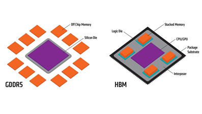
The underlying hardware difference is High Bandwidth Memory (HBM). HBM is a stack of DRAM placed onto the ASIC package as shown in the figure below. It provides high bandwidth with low power. This memory is used to expand the buffers and forwarding tables. The 8200 and 8800 use HBM. The 8100 does not.
They key message of this paper is where be cautious in deploying the 8100 Series. The paper does not address all the use cases for 8200 and 8800 Series.
Forwarding Table Size
The 8100 Series stores all forwarding tables in internal memory on the Silicon One die. This limits the FIB scale to around 400-500k IPv4 or 400-500k IPv6 entries. These are larger than other switching ASICs (e.g., Innovium and Broadcom XGS), but smaller than traditional service provider routers. The 8200 and 8800 Series store the active prefixes in internal memory and use the HBM to extend capacity. This allows for larger tables (around 2M IPv4 and 512k IPv6). In this model, the most active prefixes are stored internally, and less frequently used prefixes are kept in HBM until their traffic demands increase. As of early 2022, the Internet global tables are just above 900K IPv4 and 140K IPv6 prefixes, so 8200 and 8800 routers deployed today will support growth for many years to come.
Buffering
The difference in buffering capacity is more dramatic, and the suitability for various roles may be less intuitive. There is a great chasm between the amount of buffer memory available internally in SRAM vs. externally in the HBM. The 8100 routers offer between 64 and 108 MB of buffers in internal SRAM. The 8200 and 8800 have the internal memory and 8 GB of HBM per ASIC. The table below translates the buffer sizes into the average maximum buffer latency if all ports are congested simultaneously (an extreme worst case).
| System | MBs | Bandwidth | usec | msec |
|---|---|---|---|---|
| 8101-32H | 64 | 3200 | 160 | 0.16 |
| 8102-64H | 64 | 6400 | 80 | 0.08 |
| 8101-32FH | 108 | 12800 | 67 | 0.07 |
| 8201 | 8000 | 10800 | 5925 | 5.93 |
| 8202 | 8000 | 10800 | 5925 | 5.93 |
| 8201-32FH | 8000 | 12800 | 5000 | 5.00 |
| 8202-32FH-M | 8000 | 12800 | 5000 | 5.00 |
| 36x 400 Line Card 4x Q100 | 32000 | 14400 | 17778 | 17.78 |
| 36x 400 Line Card 3x Q200 | 24000 | 14400 | 13333 | 13.33 |
Buffer Requirements
Buffers are the shock absorbers in a network. They keep traffic flowing and minimize loss while senders react to signals from receivers to speed or slow down due to congestion. They also serve to smooth traffic between different interface speeds. The amount of buffering required depends on several factors, most importantly the round trip time (RTT), number of flows sharing the link, likelihood of congestion, transport protocol (how it detects and responds to changes), and application requirements.
There has been significant research into the impact of RTT on Internet (i.e., service provider core) buffering requirements, refer to An Update on Router Buffering and its bibliography for details. In general, longer round-trip times require more buffering as it takes longer for a signal of an event (e.g., packet loss) to reach the sender. In most core deployments, many flows share the same links. In addition, many ports share the same buffer pools. A general assumption in buffer sizing is that they will not all be congested at the same time. This means that one congested flow or port can “borrow” some of the buffer memory from the others. The extent of this has been the topic of extensive research with recommendations such as “RTT / sqrt (# flows)” or “RTT / 10” for core provider links. As ASICs capacity grows, more flows share the same buffer pool. Intuitively, this allows for more borrowing and better statistical multiplexing of buffer capacity with larger chips.
In the end, for highest performing chips there are only two hardware choices (~70 usec on-die or 5-15 msec off-die) so the key question is whether 70 usec is suitable outside of data centers. It is critical to note that the 8800 has a distributed VoQ buffer architecture. With this architecture, packets are buffered on the ingress line card. As a result, all incoming ASICs can buffer for a single congested output queue and effective buffering is far greater than what is shown above.
Data Center Requirements
For this paper, “data center” refers to ToR, leaf, and spine nodes which are part of a CloS fabric for x86 servers and participate in traffic flows that span a building or site. It does not include Data Center Interconnect routers.
Light in fiber travels approximately 200 meters per microsecond. Single ASIC switches add a few microseconds of latency when uncongested. This paper will use 3 usec as an approximation.
A data path of server -> ToR -> leaf -> spine -> superspine -> spine -> leaf -> ToR -> Server with DAC to the ToR and 100m fibers for other links would have a latency of around 15-20 microseconds plus the time the servers take to respond. This means that the RTT alone does not drive a requirement for deep buffers.
In a data center, the traffic patterns and flow characteristics are a more significant consideration. In the leaf and spine roles, the topology minimizes congestion by provisioning many parallel paths and a high cross-sectional bandwidth.
For a ToR, this isn’t the case. Many DC traffic flows are many-to-one (Incast). Hadoop is an example of this model. A server makes requests to 100s of other servers, and they all respond at the same time, possibly causing congestion on the ToR. The suitability of the 8100 for a ToR role will depend on applications and traffic patterns. Cisco has major customers who use both 8100 and 8200 as ToRs in different areas of their network.
Core, Aggregation, Data Center Interconnect, and Peering HW requirements
Routers supporting traffic that transits longer distances requires more buffering due to the increased time for flow control signals between the sender and receiver. For example, the practical RTT from New York City to Los Angeles is approximately 60 milliseconds (60,000 microseconds). If a sender is transmitting as a high rate, a 8100 Series’ buffers can be overrun before packet loss is recognized and an updated window size is received from the other end. These requirements are described in more detail in An Update on Router Buffering.
| Duration of Latency | Common Sources |
|---|---|
| 100s of nanoseconds | Nominal latency of ultra-low-latency cut-through switches |
| 1s microseconds | 10G serialization delay, nominal latency of single-chip switches |
| 10s of microseconds | Data Center RTT, Modular routers, 1G serialization |
| 1s of milliseconds | Campus or Metro RTT |
| 10s of milliseconds | Cached CDN RTT, intra-country RTT |
| 100s milliseconds | Inter-continent RTT |
| 1s of seconds | Congested DSL home router or mobile device |
Summary
The 8200 and 8800 Series support forwarding table scale and deep buffers that allow them to function in a broad range of networks roles. The 8100 Series is optimized for data center leaf, spine, and (sometimes) ToR with smaller buffers and forwarding tables. The 8100 Series should not be positioned outside the DC roles without consulting with BU technical experts.
Leave a Comment