
Cisco 8608 Architecture White Paper
Cisco 8000 Overview
The Cisco® 8000 Series combines the revolutionary Cisco Silicon One™, IOS XR® software, and clean sheet chassis design to deliver a breakthrough in high-performance routers. The 8000 Series comprises a full range of feature-rich and highly scalable and reliable routers. Cisco 8608 is a part of a new complementary portfolio built on Centralized Architecture based chassis design.
The Cisco 8608 is a unique platform that combines flexibility and reliability while offering investment protection. Customers can achieve unmatched reliability with redundant control and data plane via redundant route processors and redundant switch cards. Unlike distributed architecture, the forwarding decisions on centralized platforms are centrally performed. Cisco 8608 can also be operated in a non-redundant mode as per the appropriate customer required use case. Cisco 8608 first generation switch cards are powered by Cisco Silicon One™ Q200 NPU. A wide variety of modular port adapters allow for high interface diversity.
This data sheet is specifically for the Cisco 8608 router. In addition to the centralized router architecture in the Cisco 8608, the Cisco 8000 Series includes two other distinct router architectures that utilize the Cisco Silicon One NPU:
- Distributed: The Cisco 8800 Series provides the highest bandwidth via distributed chassis with a redundant control plane and switch fabric. The 8800 Series includes the Cisco 8804, 8808, 8812, and 8818. These chassis deliver up to 28.8 Tbps per line card via 100, 400, and 800G ports.
- Fixed: The Cisco 8100 and 8200 utilize Cisco’s standalone architecture to deliver full routing functionality with a single NPU per router. Both support the full routing feature set. The 8200 has deep buffers and expanded forwarding tables, while the 8100 is targeted for routed data center applications with lower buffering and forwarding table scale requirements.
Learn more about Cisco 8000 distributed and fixed portfolio in the Cisco 8000 data sheet.
Cisco 8608 Overview
Large, distributed chassis have traditionally been designed to cater to the market requirement for total system bandwidth, port diversity, and redundancy. The requirements far exceeded what could be accomplished with a single NPU. The fabrics that weave together multi-NPU systems had to be provisioned to the highest bandwidth use case and deployed 100% upfront, consuming power and capital regardless of the number of installed line cards. That wisdom held true for multiple generations of core, edge, and aggregation distributed systems.
Now with the advent of dense Cisco Silicon One NPU, we can address these roles with a new breed of centralized architectures that combine the best aspects of distributed and fixed systems. Cisco 8608 has combined the redundancy and I/O diversity of distributed systems with the economics and simple elegance of fixed platforms. As a result, Cisco 8608 delivers redundancy at an optimized cost while enabling flexibility and expandability through generational continuity.
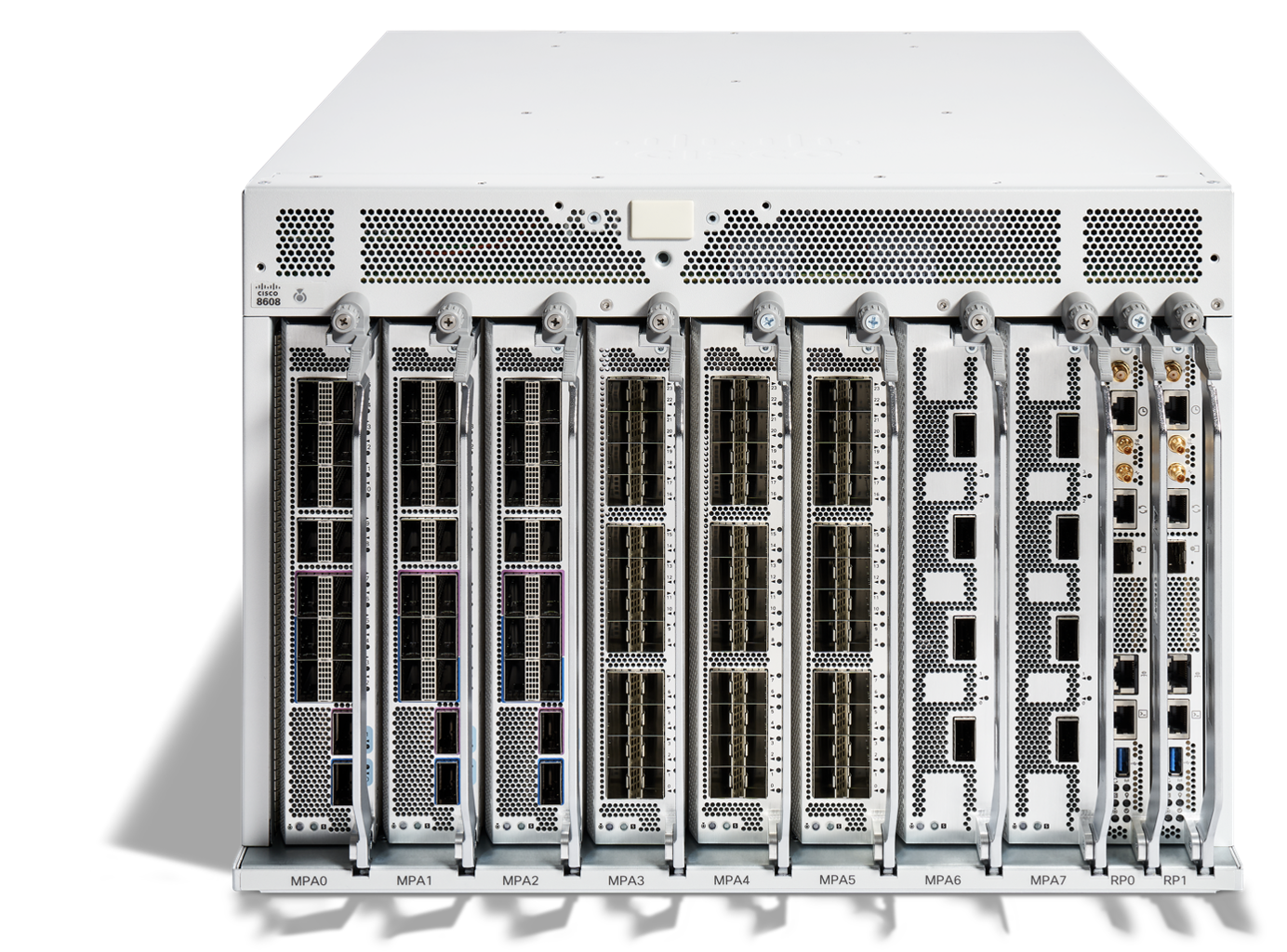
Figure 1. Front view of the Cisco 8608

Figure 2. Front view of the Cisco 8608 with Door kit
The Cisco 8608 router is 7 RU in height and less than 600mm in sheet metal depth with 8 slots for three types of MPAs (Modular Port Adapters).
Supporting the Cisco 8608 router capabilities demanded a wide range of new approaches to platform design. By leveraging decades of high-performance system design, Cisco has delivered unprecedented capacity without compromising forwarding performance. This required new power supplies, a redesigned cooling architecture, and future-proof connectors.
The Cisco 8608 router required extensive innovation and consolidation of capabilities to greatly increase the power efficiency of the solution. As with all modern networking devices the power density of the NPU creates challenging thermal conditions. These challenges are addressed via advanced system design, including optimized fans and heat sinks.
The Cisco 8608 router utilizes a state-of-the-art orthogonal design with advanced cooling via front to back airflow, high power capacity and new power supplies. The chassis and all data path components for the Cisco 8608 router benefit from a clean sheet design that allows the systems to take full advantage of the latest technologies and Cisco’s design expertise. This design connects all forwarding path components directly without a backplane or midplane. In the Cisco 8608 router, the eight Modular Port Adaptors (MPAs) along with the two Route Processors are vertically oriented. Every major component of the Cisco 8608 router was developed with a clean sheet approach – representing unprecedented investment and commitment to a long lifecycle for the Cisco 8608 router.
Investment Protection – The design of the system keeps in mind the ability to upgrade all the major components of the Chassis (Switch Card, Route Processor &and Modular Port Adaptors). Cisco is investing in the future of the platform for the customers to be able to upgrade to the next generation.
The key chassis components and their overview is captured in the table below:

Table 1. Cisco 8608 key components
Cisco 8608 value proposition
Redundancy: Cisco 8608 introduces a new forwarding paradigm via a redundant control plane (route processor [RP] redundancy) and redundant data plane (switch card [SC] redundancy). A redundant 8608 requires two RPs and two SCs, while a nonredundant 8608 is comprised of a single RP & SC.
Investment Protection: The design of the system keeps in mind the ability to upgrade all the major components of the Chassis (Switch Card, Route Processor and Modular Port Adaptors). Cisco is investing in the future of the platform for customers to be able to upgrade to the next generation.
Flexibility: Flexibility via MPA modularity and interface diversity. Native port speed support from 10 GbE upto 400 GbE. Wide variety of optics support for multiple customer use cases.
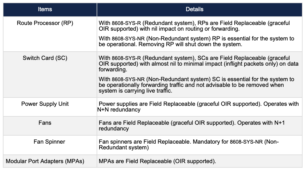
Table 2. Cisco 8608 Field Replaceable Units
Cisco 8608 PIN(Place In Network) Use cases
Core LSR/IP and Peering
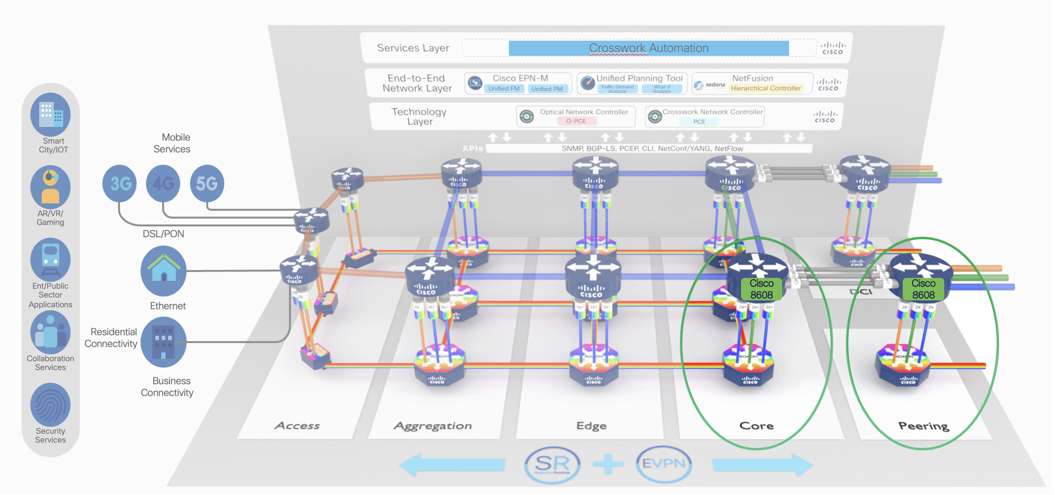
As the user applications are becoming more dynamic, requiring differentiated user experiences network resources needs to be optimized in terms of power and real estate. Cisco 8608 has been designed to cater the market requirement for total system bandwidth, port diversity, and full redundancy. The requirements far exceeded what could be accomplished with a single NPU. Cisco 8608 supports 12.8 Tbps of forwarding capacity. It provides 32 ports of high speed 400G including 400G Bright ZR+ or 128 ports of 100G or 192 ports of low speed 10G/25G in the system.
IP and Optical Convergence - The Journey Ahead
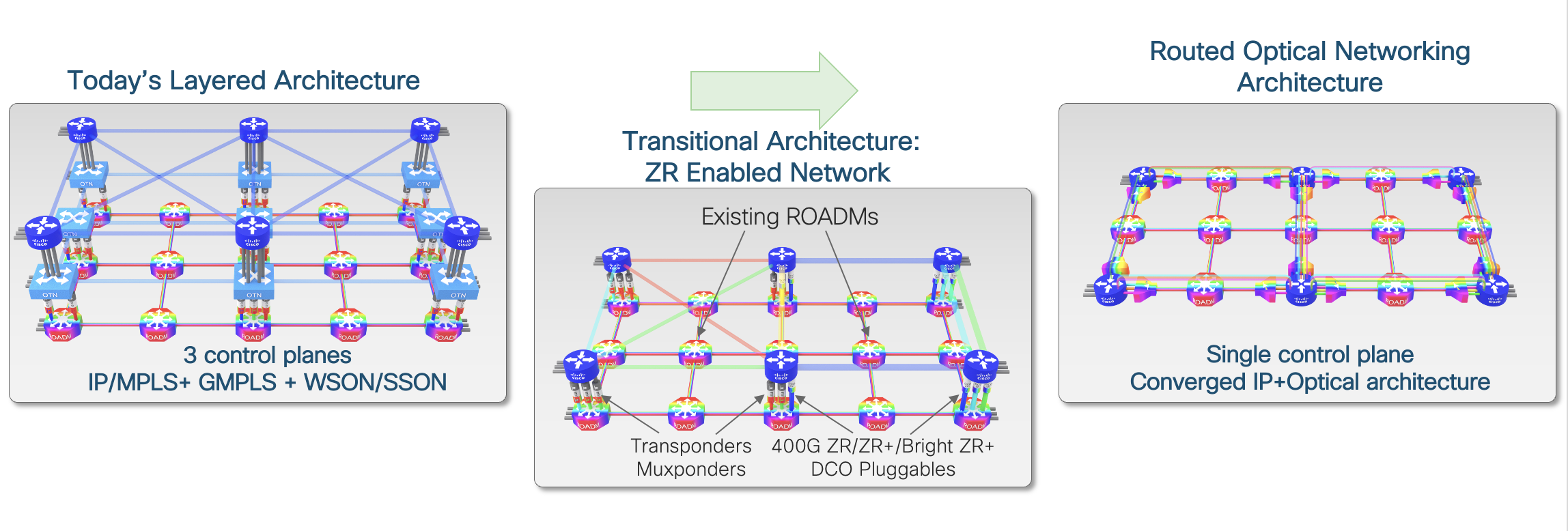
Cisco’s Converged SDN Transport Solution, is an architecture that delivers efficient network utilization, Simplified single layer, reduced network complexity, faster time to market, automation empowerment, and differentiated service offering. The solution works by merging IP and Optical onto a single layer where all the switching is done at Layer 3. Routers are connected with standardized 400G ZR/ZR+/Bright(0dBm) ZR+ coherent pluggable optics. With a single service layer based upon IP, flexible management tools can leverage telemetry and model-driven programmability to streamline lifecycle operations.
Understanding the Cisco 8608 Naming Logic
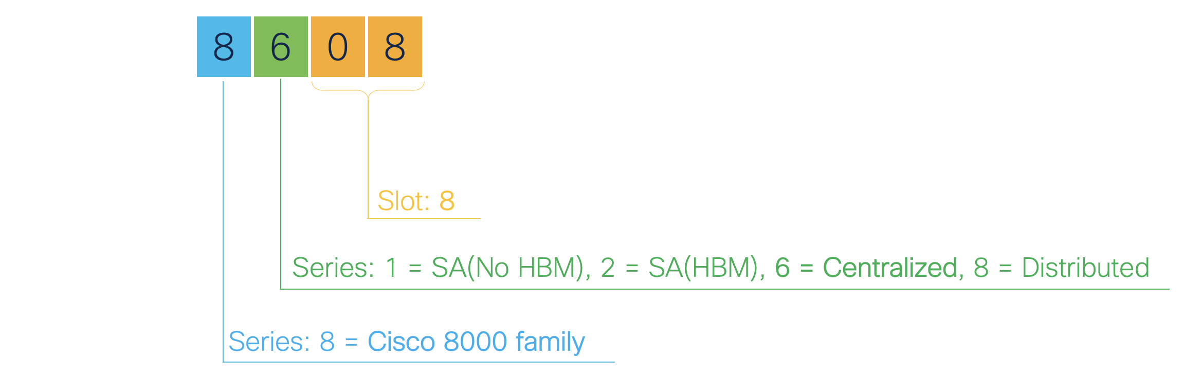
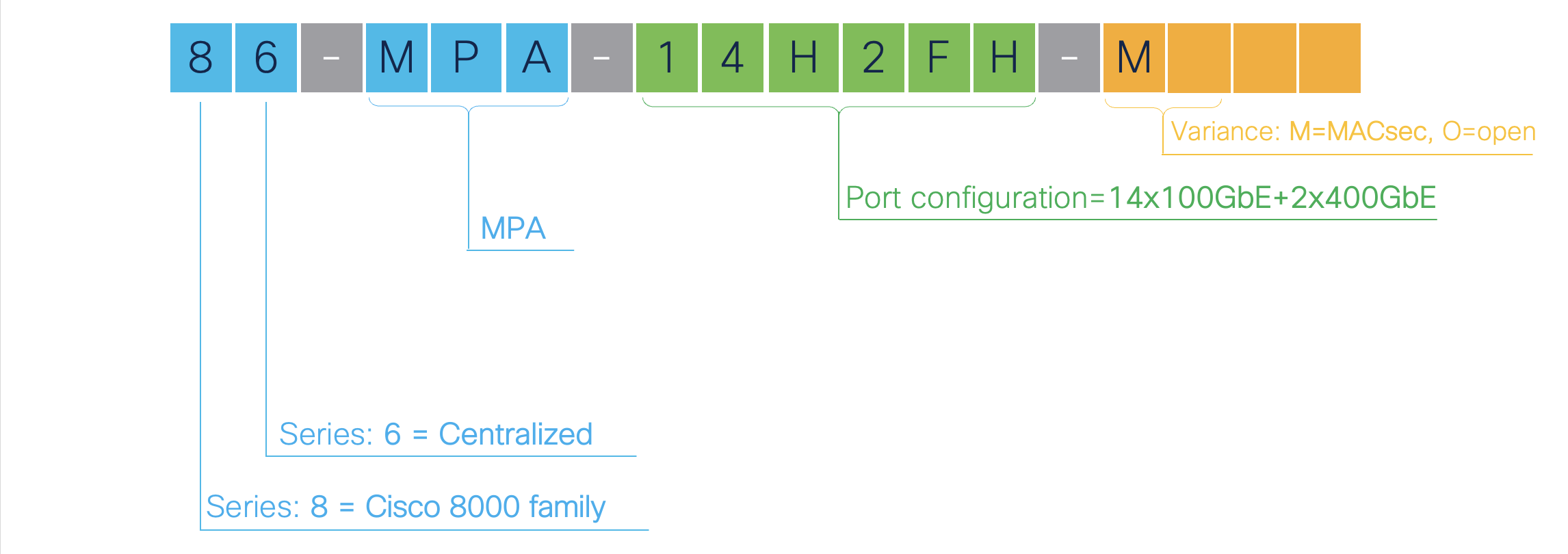
Let us have a quick refresher of the Cisco 8608’s PIDs and description.
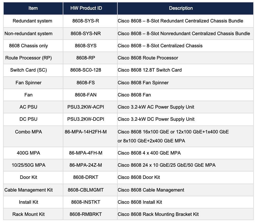
Table 3. Cisco 8608 PID and description
Platform Description
Chassis
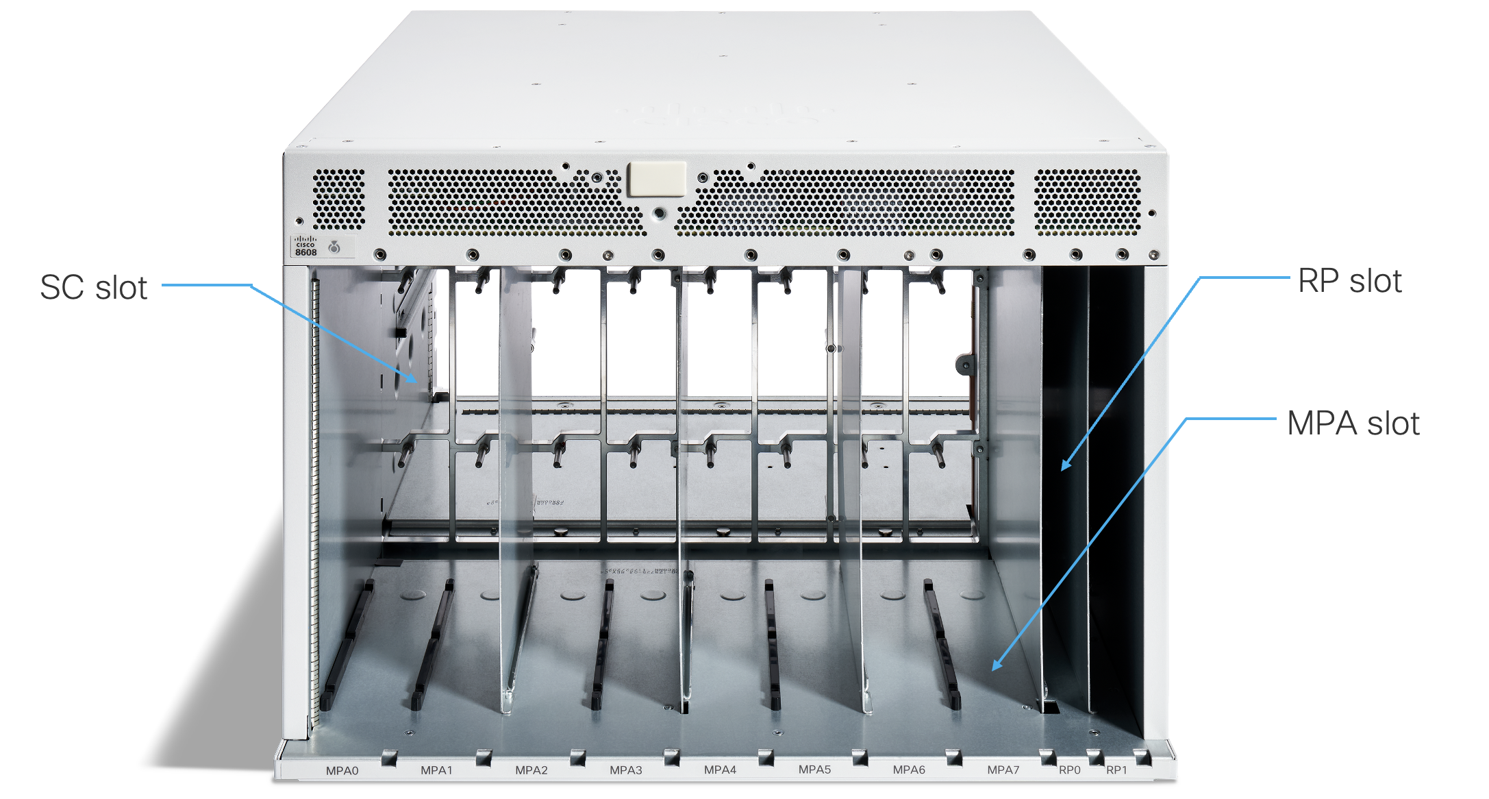
Figure 3. Front view of an empty Cisco 8608 chassis
As shown in Figure 3, user needs to insert the followings:
- Modular Port Adapter(MPA) sits vertically in the front of the chassis
- Route Processor(RP) sits vertically in the front of the chassis
- Switch Card(SC) sits horizontally behind the Fan Trays. Cisco 8608 router has two Fan Trays with four Fan Modules on each Fan Tray

Figure 4. Back view of Cisco 8608 chassis with 8 FMs and 4 PMs
In Figure 4, there are 2 Fan Trays with eight Fan Modules and four Power Modules

Figure 5. Side view of Cisco 8608 chassis
The Route Processors(RPs) are vertically inserted into the front right hand side of the Cisco 8608 chassis.
The Module Port Adapters(MPAs) are vertically inserted into the front side of the Cisco 8608 chassis, to the left of the RPs.
The Switch Cards(SC0, SC1) that include the packet processing and forwarding engine using Cisco Silicon One Q200 are horizontally inserted into the back of the chassis. There are 2 switch cards per system. The Switch Cards contain the four removable Fan Modules.
MPA (Modular Port Adapter)
The Cisco 8608 router centralized platform supports three different Redundant Modular Port Adapters(MPAs) to insert into slots 0 to 7.
- All MPAs support MACsec, regardless of the slot of insertion.
- These MPAs are CPU-less and have the PHY and Optics components for network connectivity to other devices in the network. Each MPA connects to both Switch Cards (SC0, SC1).
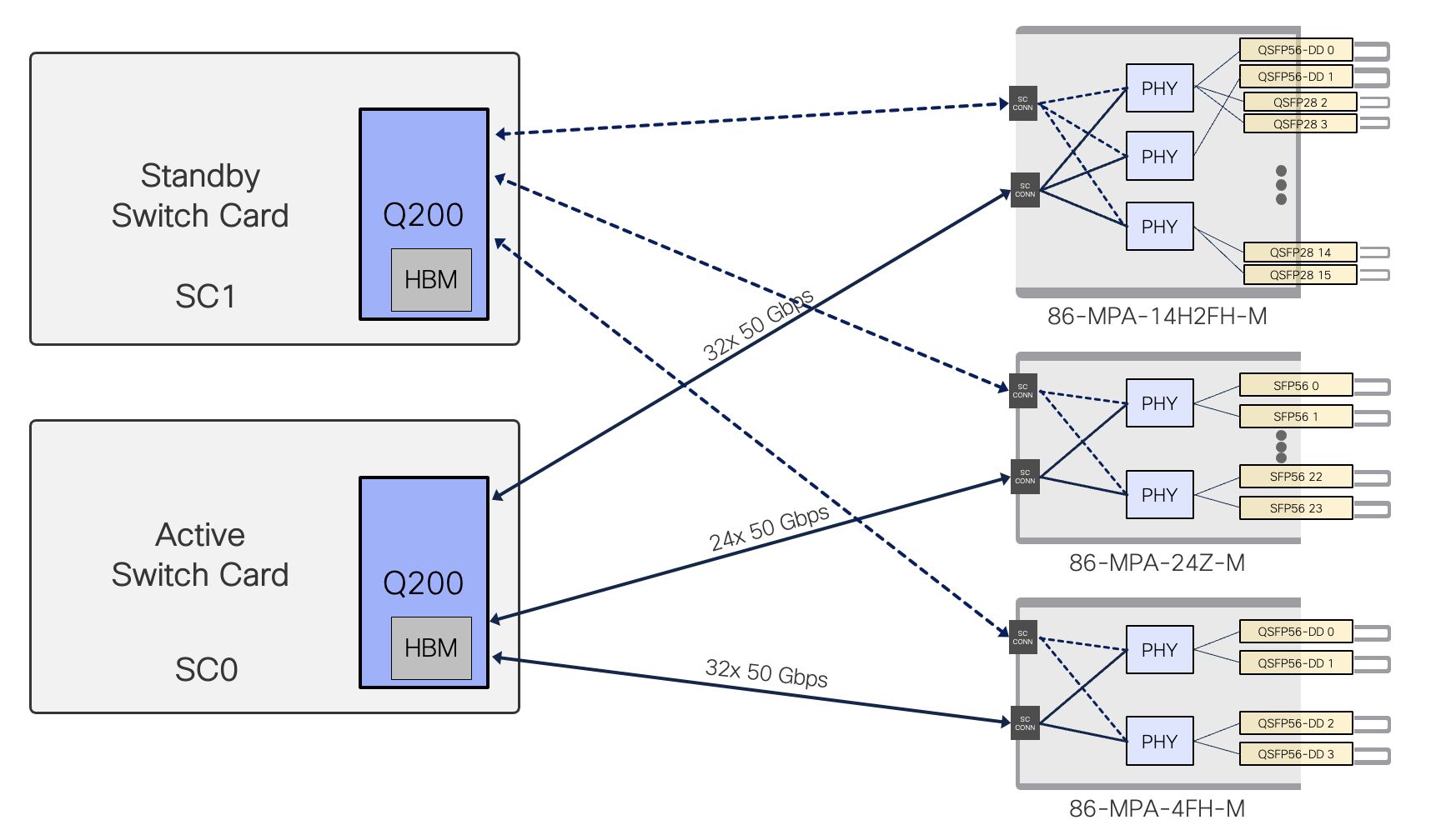
Figure 6. two SCs and three Redundant MPAs connection of Cisco 8608 chassis
The Q200 on the SC has up to 32x 50Gbps SerDes to each MPA slot regardless of slot number.
Cisco 8608 modular port adapters
The Cisco 8608 supports three different modular port adapters (MPAs). The details are captured in table below:
| Modular Port Adapter | Bandwidth | 10/25/50 GbE Physical Ports | 100 GbE Physical Ports | 400 GbE Physical Ports | MACsec | PTP Timing |
|---|---|---|---|---|---|---|
| 86-MPA-14H2FH-M | 1.6 Tbps | - | 14 | 2 | Yes | Class C |
| 86-MPA-24Z-M | 1.2 Tbps | 24 | - | - | Yes | Class C |
| 86-MPA-4FH-M | 1.6 Tbps | - | - | 4 | Yes | Class C |
86-MPA-14H2FH-M
86-MPA-14H2FH-M can be inserted into any slot (slot 0 to slot 7) of the chassis without any restriction. This MPA is a pluggable card that provides 16 interface ports for a maximum total bandwidth of 1.6 Tbps that can support up to:
- 16 ports of QSFP 100 GbE modules (Default), or
- 2 ports of QSFP-DD 400 GbE modules and 14 ports of QSFP When port 0 has a 400G QSFP-DD, then the other three ports (2, 3, 4) cannot be used. Similarly, when port 1 has a 400G QSFP-DD, then the other three ports (5, 6, 7) cannot be used.
Note: No restriction in term of power or cooling for 400G ZR/ZR+/Bright ZR+
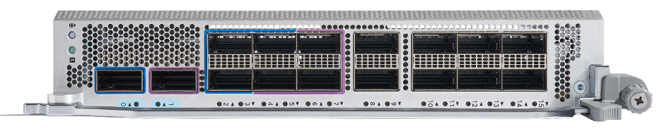
Figure 7. 86-MPA-14H2FH-M
86-MPA-4FH-M
86-MPA-4FH-M can be inserted into any slot (slots 0 to 7) of the chassis without any restriction. This MPA is a pluggable card that provides 4 interface ports for a maximum total bandwidth of 1.6 Tbps and can support up to:
- 4 ports of QSFP-DD 400 GbE modules
Note: No restriction in term of power or cooling for 400G ZR/ZR+/Bright ZR+
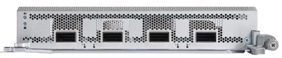
Figure 8. 86-MPA-4FH-M
86-MPA-24Z-M
86-MPA-24Z-M can be inserted into any slot (slot 0 to 7) of the chassis without any restriction. This MPA is a pluggable card that provides 24 interface ports for a maximum total bandwidth of 1.2 Tbps and can support up to:
- 24 ports of SFP56 1/10/25/50 GbE modules

Figure 9. 86-MPA-24Z-M
RP (Route Processor)
The Cisco 8608 route processor (RP) sits vertically in the front of the chassis handling control plane and management plane operations. In addition to other ports, the RP has the timing ports on it. The RP is not SerDes connected to the Switch Card.
- Redundant 8608 : There will be two RPs in the system which work in Active-standby mode.
- Non-Redundant 8608 : There will be a single RP in the system . This kind of a system does not offer any control plane redundancy.
RPs manage all routing operations on the Cisco 8608 Routers.
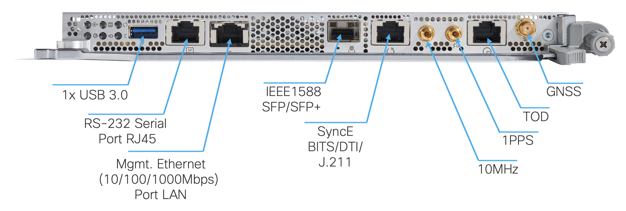
Figure 10. 8608-RP
Front panel ports include management and Timing interfaces:
- RJ45 console port directly connected to CPU
- 10/100/1000 Mbps Management Ethernet Port
- USB 3.0 (Type A)
- Timing ports: 1588 PTP SFP, SyncE, BITS, GNSS PRTC-A, and GPS(ToD with RJ45 port, 1PPS and 10MHz coax input)
RP contains an Intel 6-core @ 2.5 GHz, 64GB DDR4 DRAM, and 256 GB M.2 SSD Flash Drive.
This RPs are connected to the midplane and communicate with their devices via PCIE etc.
SC (Switch Card)
The Cisco 8608 router Switch Card sits behind the Fan Trays. Cisco 8608 router has two Fan Trays with a total of eight Fan Modules. The Cisco Silicon One Q200 sits within the Switch Card and all the packet process and forwarding decisions are driven by the Switch Card.
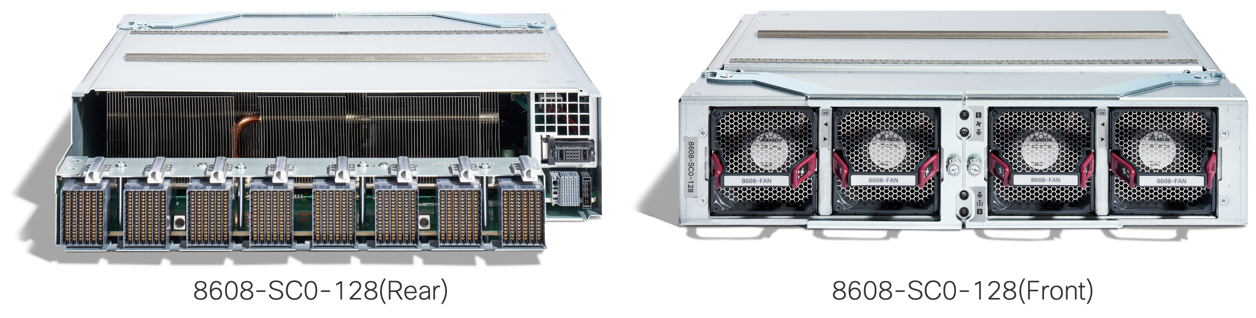
Figure 11. 8608-SC0-128
Cisco 8608 can operate with up to 2 Switch Cards(SCs) between MPA and Fan Trays.
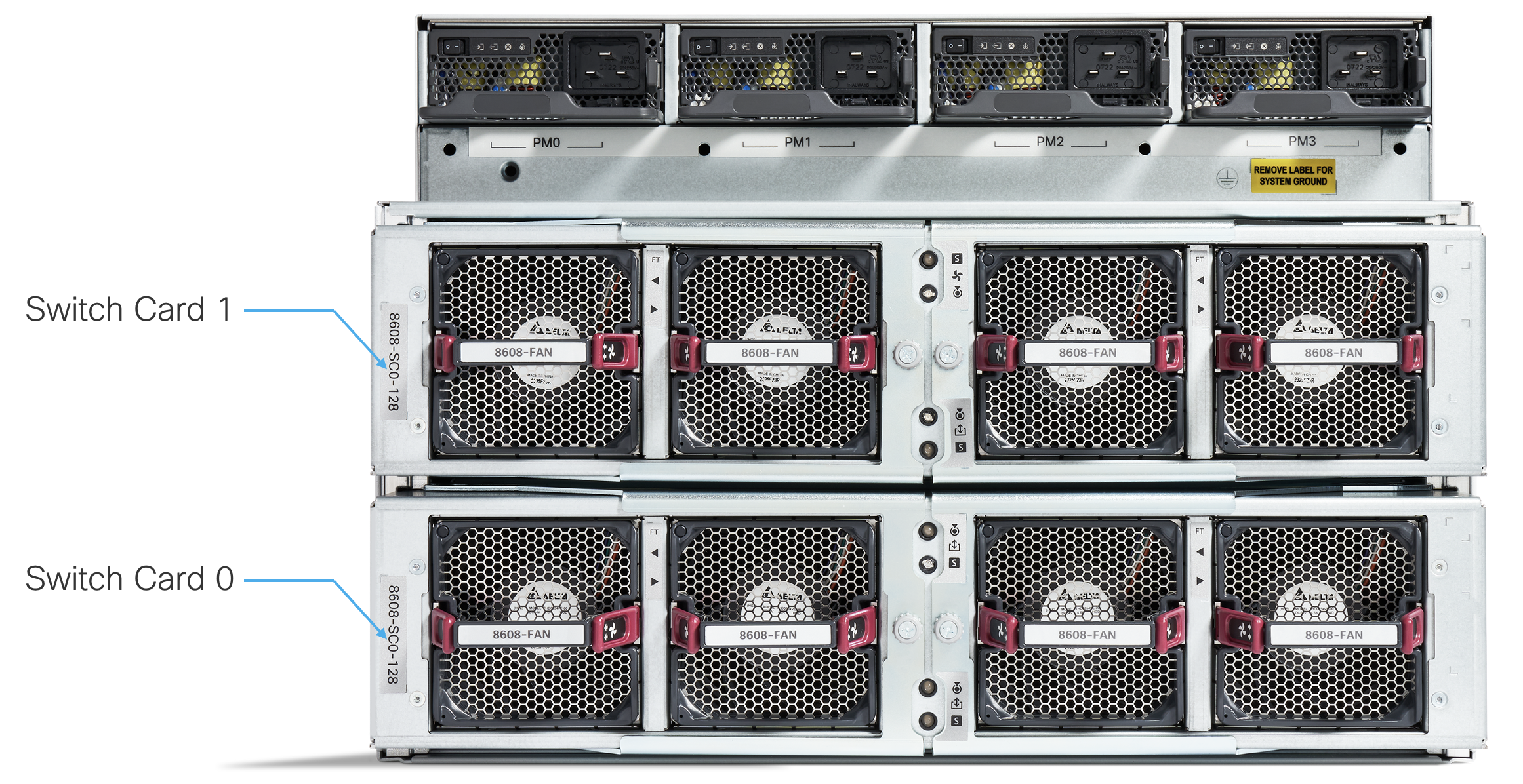
Figure 12. Redundant SCs in the back of the Cisco 8608
The RP & SC operate in pairs RP0-SC0 and RP1-SC1 to deliver redundancy without bandwidth loss.
The two SCs are CPU-less connected to both the RPs via PCIE, P2PM, EOBC links and each SC has one Cisco Silicon One Q200 providing the data path for packet processing and forwarding.
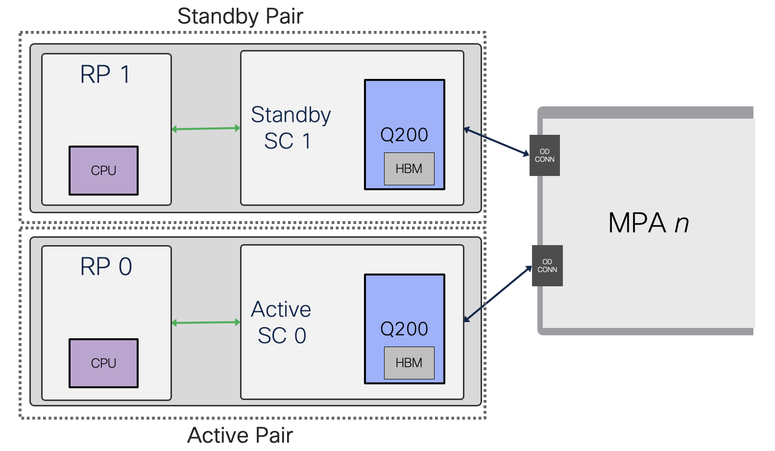
Figure 13. Redundant System
The SC is installed in the rear of the chassis. The 8 Fan Modules are installed into the SCs. If you need to remove or replace the SC, we recommend that you remove the Fan Modules.
Note: To avoid over-heating the system, the service time between when a Switch Card or Fan Spinner is removed and re-inserted must be under 3 minutes.
If there is only one SC card plugged in, a Fan Spinner card will be required which is essentially a SC blank slot with a Fan Controller and Fan Modules.

Figure 14. Non-Redundant System
Fan Spinner does not provide any data or control plane functionality. It is a passive card used to connect the midplane to the Fans.
Power Modules
Cisco 8608 can be installed with up to four 3200W AC or 3200W DC power supplies in the chassis. Ensure that all power connection wiring conforms to the rules and regulations in the National Electrical Code (NEC) and local codes.
Note: The Cisco 8608 chassis doesn’t support a mix of AC and DC Power Supply Units (PSUs)
AC Power Module (PSU3.2KW-ACPI)
- The AC power modules are single feed with 3200W capacity at 220V. They also support operation at 110V with half the capacity.
- AC power modules are rated at 3200W maximum at 230V AC high line input, and 1570W maximum at 115V AC low line input.
- AC nominal range: 100 to 120V AC and 200 to 240V AC
- AC full range: 85 to 132V AC and 180 to 264V AC; with extended range to 300V AC
DC Power Module (PSU3.2KW-DCPI)
- The DC power modules are dual feed with 3200W capacity at any specified input voltage. DC power modules with single feed at any specified input voltage provide up to 1600W maximum capacity.
- DC nominal range: -48 to -60V DC
- DC full range: -40 to -75V DC
The airflow direction through the Fan Trays and Power Modules on the Cisco 8608 routers are from front to back (port side intake).
The maximum power available for operations depends on the input power from your power source, the number and output capabilities of power supplies, and the power redundancy mode that you use.
The following table lists the amount of power available for Cisco 8600 series routers from all available power trays.
| Total Power Supply | Combined Mode in Watts(No redundancy) | N+1 Redundancy Mode in Watts (with Single Supply Loss) |
|---|---|---|
| 1 | 3,190 | - |
| 2 | 6,380 | 3,190 |
| 3 | 9,570 | 6,380 |
| 4 | 12,760 | 9,570 |
RP/0/RP0/CPU0:Cisco8608#sh platform
0/RP0/CPU0        8608-RP(Active)          IOS XR RUN               NSHUT
0/RP1/CPU0        8608-RP(Standby)         IOS XR RUN               NSHUT
0/SC0             8608-SC0-128             OPERATIONAL              NSHUT
0/SC1             8608-SC0-128             OPERATIONAL              NSHUT
0/FB0             8608-SC0-128[FB]         OPERATIONAL              NSHUT
0/FB1             8608-SC0-128[FB]         OPERATIONAL              NSHUT
0/0               86-MPA-4FH-M             OPERATIONAL              NSHUT
0/4               86-MPA-14H2FH-M          OPERATIONAL              NSHUT
0/5               86-MPA-24Z-M             OPERATIONAL              NSHUT
0/6               86-MPA-14H2FH-M          OPERATIONAL              NSHUT
0/7               86-MPA-14H2FH-M          OPERATIONAL              NSHUT
0/FT0             8608-FAN                 OPERATIONAL              NSHUT
0/FT1             8608-FAN                 OPERATIONAL              NSHUT
0/FT2             8608-FAN                 OPERATIONAL              NSHUT
0/FT3             8608-FAN                 OPERATIONAL              NSHUT
0/FT4             8608-FAN                 OPERATIONAL              NSHUT
0/FT5             8608-FAN                 OPERATIONAL              NSHUT
0/FT6             8608-FAN                 OPERATIONAL              NSHUT
0/FT7             8608-FAN                 OPERATIONAL              NSHUT
0/PM0             PSU3.2KW-ACPI            OPERATIONAL              NSHUT
0/PM1             PSU3.2KW-ACPI            OPERATIONAL              NSHUT
Note: FB0/FB1 are not externally visible.
On this router, there are two Power Modules in Cisco 8608 chassis.
RP/0/RP0/CPU0:Cisco8608#sh environment power
================================================================================
CHASSIS LEVEL POWER INFO: 0
================================================================================
   Total output power capacity (N + 1)             :    6400W +        0W
   Total output power required                     :    4465W
   Total power input                               :    1122W
   Total power output                              :    1028W
================================================================================
   Power       Supply         ------Input----   ------Output---     Status
   Module      Type            Volts     Amps    Volts     Amps
================================================================================
   0/PM0       PSU3.2KW-ACPI   207.9     2.8     54.7      9.8      OK
   0/PM1       PSU3.2KW-ACPI   207.9     2.6     54.7      9.0      OK
Total of Power Modules:       1122W/5.4A              1028W/18.8A
================================================================================
   Location     Card Type               Power       Power        Status
                                        Allocated   Used
                                        Watts       Watts
================================================================================
   0/RP0/CPU0   8608-RP                 200         53           ON
   0/RP1/CPU0   8608-RP                 200         52           ON
   0/SC0        8608-SC0-128            542         164          ON
   0/SC1        8608-SC0-128            542         165          ON
   0/FB0        8608-SC0-128[FB]        10          -            ON
   0/FB1        8608-SC0-128[FB]        10          -            ON
   0/0          86-MPA-4FH-M            209         115          ON
   0/1          -                       32          -            RESERVED
   0/2          -                       32          -            RESERVED
   0/3          -                       32          -            RESERVED
   0/4          86-MPA-14H2FH-M         290         156          ON
   0/5          86-MPA-24Z-M            198         77           ON
   0/6          86-MPA-14H2FH-M         284         149          ON
   0/7          86-MPA-14H2FH-M         284         147          ON
   0/FT0        8608-FAN                200         12           ON
   0/FT1        8608-FAN                200         12           ON
   0/FT2        8608-FAN                200         12           ON
   0/FT3        8608-FAN                200         12           ON
   0/FT4        8608-FAN                200         15           ON
   0/FT5        8608-FAN                200         15           ON
   0/FT6        8608-FAN                200         15           ON
   0/FT7        8608-FAN                200         15           ON
RP/0/RP0/CPU0:Cisco8608#sh environment fan
=============================================================
                                              Fan speed (rpm)
Location      FRU Type                        FAN_0    FAN_1
-------------------------------------------------------------
0/FT0        8608-FAN                           3840    3840
0/FT1        8608-FAN                           3840    3840
0/FT2        8608-FAN                           3840    3810
0/FT3        8608-FAN                           3870    3810
0/FT4        8608-FAN                           3930    3870
0/FT5        8608-FAN                           3870    3930
0/FT6        8608-FAN                           3900    3870
0/FT7        8608-FAN                           3870    3900
0/PM0        PSU3.2KW-ACPI                      5225    5247
0/PM1        PSU3.2KW-ACPI                      5204    5247
IOS XR Software
The Cisco 8608 is launched with IOS XR 7.10.1.
RP/0/RP0/CPU0:Cisco8608#sh version

Cisco IOS XR Software, Version 7.10.1 LNT
Copyright (c) 2013-2023 by Cisco Systems, Inc.

Build Information:
 Built By     : deenayak
 Built On     : Wed Aug 16 23:51:31 UTC 2023
 Build Host   : iox-ucs-058
 Workspace    : /auto/srcarchive16/prod/7.10.1/8000/ws/
 Version      : 7.10.1
 Label        : 7.10.1

cisco 8000 (Intel(R) Xeon(R) CPU D-1633N @ 2.50GHz)
cisco 8608-SYS (Intel(R) Xeon(R) CPU D-1633N @ 2.50GHz) processor with 64GB of memory
Cisco8608 uptime is 7 minutes
Cisco 8600 - 8 Slot Centralized Chassis
Detailed information on XR7 can be found here: IOS XR Data Sheet. For a complete list of supported features, refer to the Cisco Feature Navigator. Cisco Software Download page to download the Cisco IOS XR software images.
Cisco 8608 Slot and Port identification
Slots numbering on the Cisco 8608 from the front goes On front view of the Cisco 8608 chassis, left to right direction is MPA0 to MPA7 and, RP0 to RP1.
Slots numbering
On front view of the Cisco 8608 chassis, left to right direction is MPA0 to MPA7, RP0 to RP1.
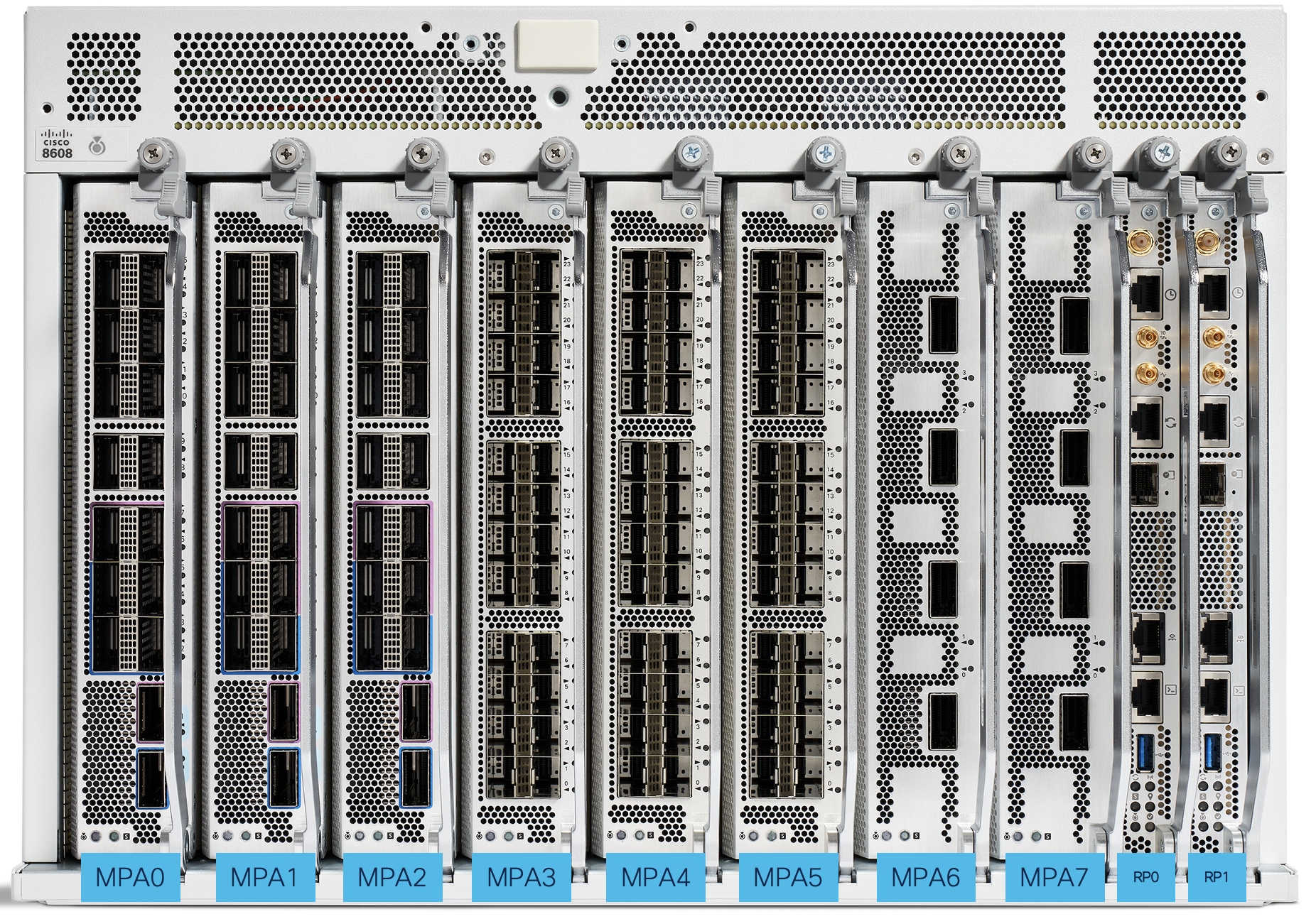
Figure 15. Cisco 8608 Slot numbering
Port numbering
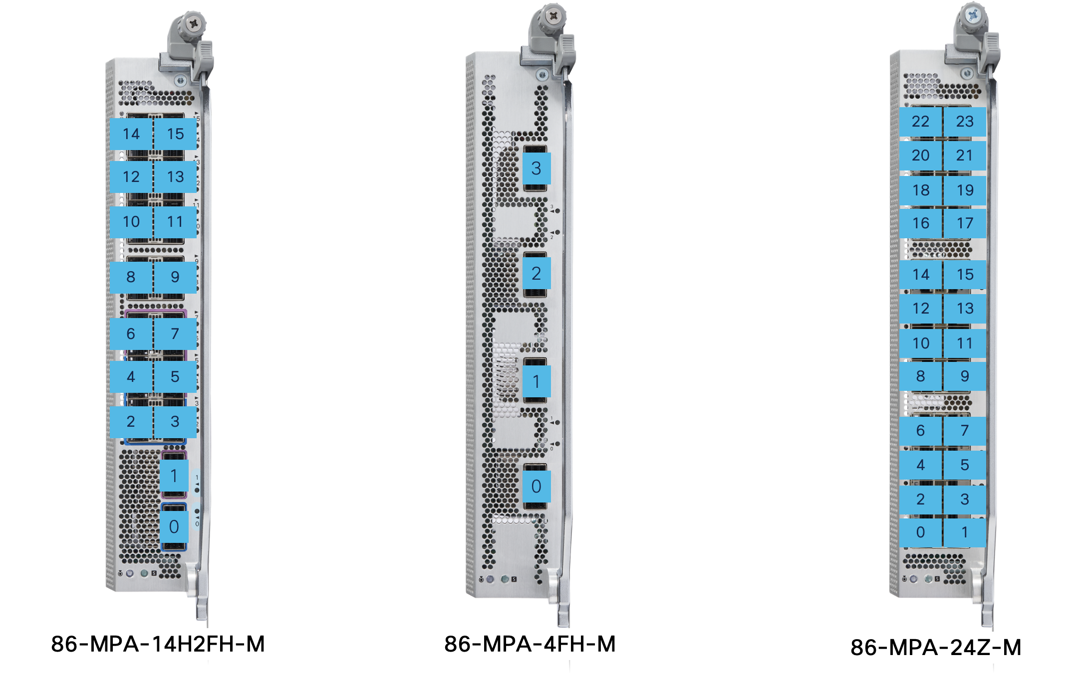
Figure 16. Cisco 8608 MPA Port numbering
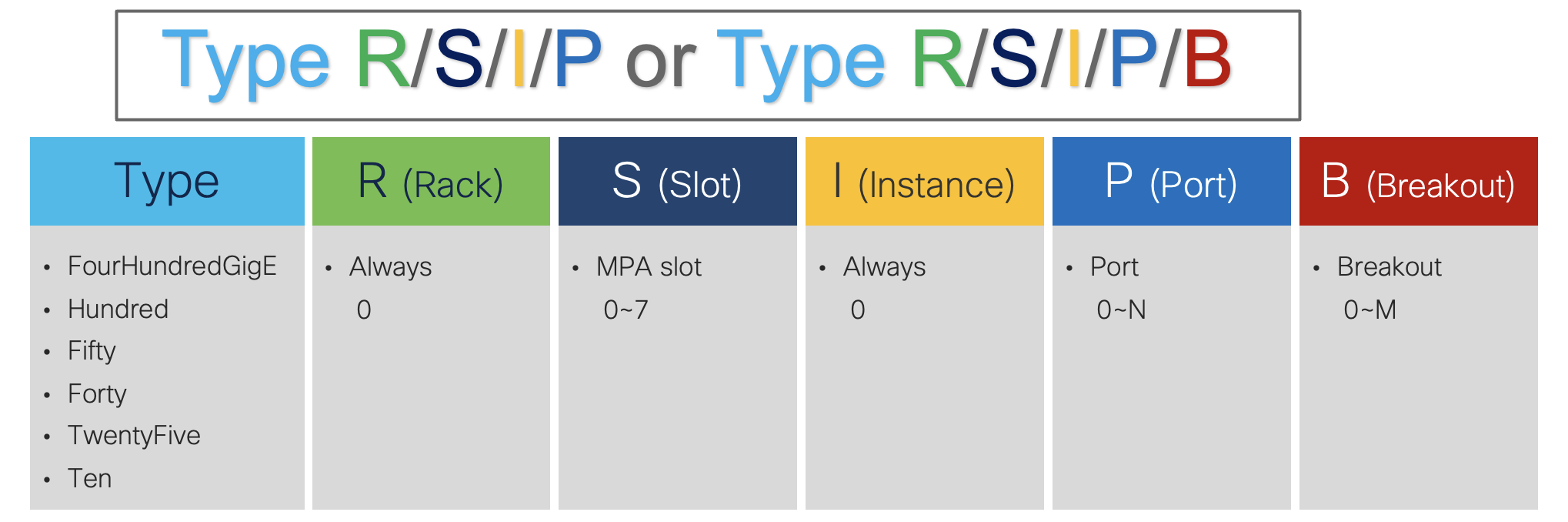
Cisco 8608 port numbering follows that of physical interfaces as {Type}{R/S/I/P} or {Type}{R/S/I/P/B}
Native Interface Use-case: 86-MPA-4FH-M MPA at port 0 & 1 with native 100 GbE and port 2 & 3 with native 400 GbE on slot 0
RP/0/RP0/CPU0:Cisco8608#sh interfaces brief

               Intf       Intf        LineP              Encap  MTU        BW
               Name       State       State               Type (byte)    (Kbps)
--------------------------------------------------------------------------------
         Hu0/0/0/0          up          up               ARPA  9000  100000000
         Hu0/0/0/1          up          up               ARPA  9000  100000000
       Hu0/0/0/1.1          up          up             802.1Q  9004  100000000
       Hu0/0/0/1.2          up          up             802.1Q  9004  100000000
       Hu0/0/0/1.3          up          up             802.1Q  9004  100000000
       Hu0/0/0/1.4          up          up             802.1Q  9004  100000000
       Hu0/0/0/1.5          up          up             802.1Q  9004  100000000
       Hu0/0/0/1.6          up          up             802.1Q  9004  100000000
       Hu0/0/0/1.7          up          up             802.1Q  9004  100000000
       Hu0/0/0/1.8          up          up             802.1Q  9004  100000000
       Hu0/0/0/1.9          up          up             802.1Q  9004  100000000
         FH0/0/0/2          up          up               ARPA  9000  100000000
         FH0/0/0/3          up          up               ARPA  9000  100000000
Breakout Interface Use-case: 86-MPA-14H2FH-M MPA at port 14 with 4x10 GbE on slot 7
RP/0/RP0/CPU0:Cisco8608#sh interfaces brief

               Intf       Intf        LineP              Encap  MTU        BW
               Name       State       State               Type (byte)    (Kbps)
--------------------------------------------------------------------------------
       Te0/7/0/14/0          up          up               ARPA  1514   10000000
       Te0/7/0/14/1          up          up               ARPA  1514   10000000
       Te0/7/0/14/2          up          up               ARPA  1514   10000000
       Te0/7/0/14/3          up          up               ARPA  1514   10000000
System Details
System Block Diagram
Inside the chassis, there are two Route Processors (RPs), two Switch Cards (SCs), eight Modular Port Adapters (MPAs), 4 Power Modules (PMs), 8 Fan Modules (FMs) – all these entities are field replaceable units (FRUs).
- Route Processor (2 for redundant mode, 1 for non-redundant mode)
- Intel 6-core @ 2.5 GHz with DDR4 DRAM and SSD Flash
- PCIE, P2PM, 10 GbE for control
- Trusted Anchor Module (TAM) for secure boot
- Switch Card (2 for redundant mode, 1 for non-redundant mode)
- Each SC has one Cisco Silicon One Q200 NPU with 8 GB HBM
- PCIE switch to interconnect the key components
- Fan Controller Board
- Orthogonal Connector to all inter-connectivity with the MPAs
- Modular Port Adapter
- PHY supports hitless 2:1 Mux mode, MACsec, Reverse Gearbox, Class C PTP
- PHY provides an interface to front panel ports and connects to the Q200 on SC
- Orthogonal SC connector
- FPGA for control signals
- Front panel ports

Figure 17. Cisco 8608 Block Diagram
Switch Card (SC) Details
Switch Card has 12.8T bandwidth using the Cisco Silicon One Q200 at an operating data rate of 50 Gbps SerDes. It supports 8 pluggable modular port adapter (MPA) cards each supporting up to 1.6 Tbps. There can be two SCs in a system that provide full data plane redundancy in an active-standby mode.
Cisco Silicon One Q200 features:
- 12.8 Tbps full-duplex and 8.1 Bpps Forwarding Capacity NPU
- 256x 50G SerDes with each capable of operating at 10G/25G/50G using NRZ or PAM4 modulation
- Flexible port configuration supporting 10/25/40/50/100/400 Gbps
- 108 MB fully shared on-die packet buffer
- Expandable in-package packet buffer using 8 GB HBM
- On-chip, high-performance, P4-programmable host NPU for high-bandwidth offline packet processing
- Multiple embedded processors for CPU offloading
- 56K VoQ(Virtual Output Queue)
- Dedicated 108 Counters banks (860K counters)
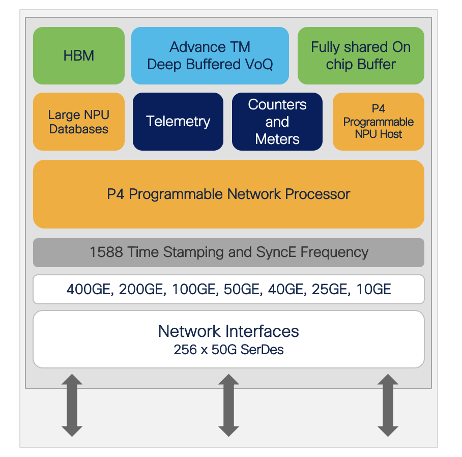
Figure 18. Cisco Silicon One Q200
For more understanding on Cisco Silicon One Q200 refer to Cisco Silicon One Q200-Info.
MPA assignment to Cisco Silicon One Q200 in SC
Cisco 8608 is straightforward in terms of MPA slot positioning where any of the 8 MPA slots can accommodate any MPA variants. There is no MPA slot restrictions in the chassis.
There is one Q200 in each Switch Card.
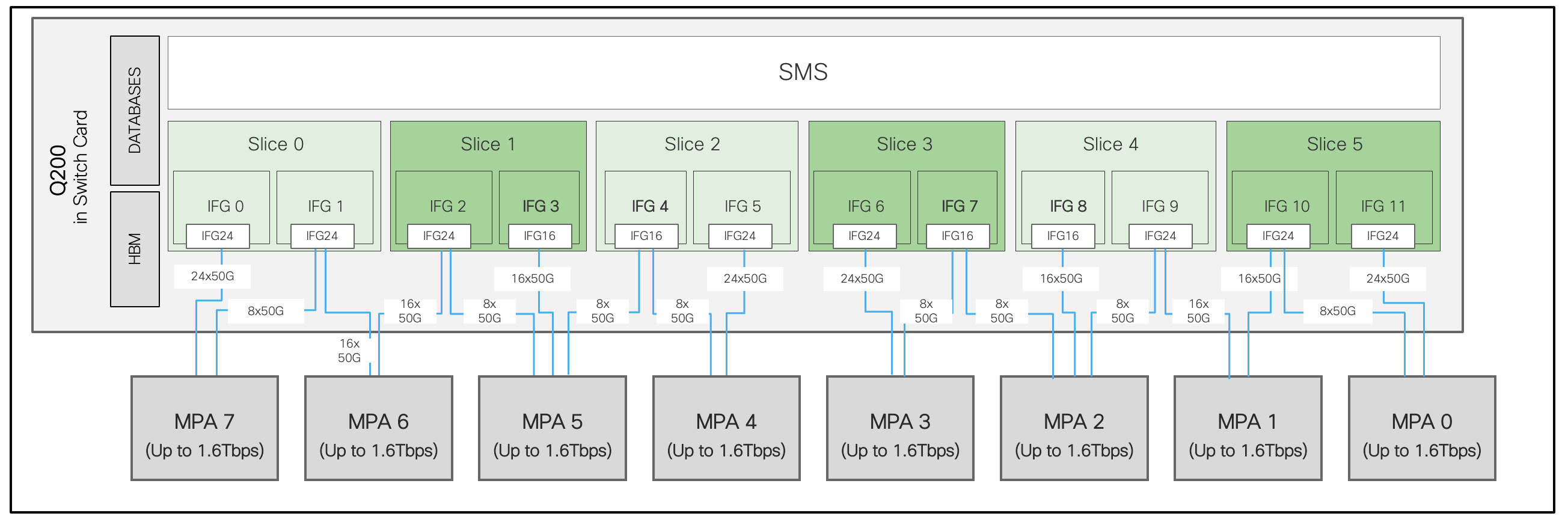
Figure 19. Cisco 8608 MPA assignment to Q200
Each SC is connected to MPA 0 to MPA 7. Maximum MPA bandwidth to Q200 is 1.6 Tbps. And so a total of 12.8 Tbps duplex per Cisco 8608 system.
There is a Cisco 8608 with the MPA in slot 1(86-MPA-14H2FH-M) and slot 2(86-MPA-4FH-M). Let’s concentrate on slot 2 for this example.
RP/0/RP0/CPU0:Cisco8608#show controllers npu voq-usage interface all instance all loc 0/rp0/cpu0
---------------------------------------------------------------------------
Node ID: 0/RP0/CPU0
Intf         Intf     NPU Slice IFG  Sys   VOQ   Flow       VOQ      Port
name         handle    #    #    #   Port  base  base       port     speed
             (hex)                                          type
---------------------------------------------------------------------------
Hu0/1/0/15   f0000dc   0   5    0   320    632      0        local    100G
Hu0/1/0/14   f0000e4   0   5    0   312    624      0        local    100G
Hu0/1/0/13   f0000ec   0   5    0   304    616      0        local    100G
Hu0/1/0/12   f0000f4   0   5    0   296    608      0        local    100G
Hu0/1/0/11   f0000fc   0   5    0   288    600      0        local    100G
Hu0/1/0/10   f000104   0   5    0   280    592      0        local    100G
Hu0/1/0/9    f00010c   0   5    0   272    584      0        local    100G
Hu0/1/0/8    f000114   0   5    0   264    576      0        local    100G
Hu0/1/0/7    f00011c   0   4    1   256    568      0        local    100G
Hu0/1/0/6    f000124   0   4    1   248    560      0        local    100G
Hu0/1/0/5    f00012c   0   4    1   240    552      0        local    100G
Hu0/1/0/4    f000134   0   4    1   232    544      0        local    100G
Hu0/1/0/3    f00013c   0   4    1   224    536      0        local    100G
Hu0/1/0/2    f000144   0   4    1   216    528      0        local    100G
Hu0/1/0/1    f00014c   0   4    1   208    520      0        local    100G
Hu0/1/0/0    f0000d4   0   4    1   200    512      0        local    100G
FH0/2/0/3    f00017c   0   4    1   416    672      0        local    400G
FH0/2/0/2    f000184   0   4    0   408    664      0        local    400G
FH0/2/0/1    f00018c   0   4    0   400    656      0        local    400G
FH0/2/0/0    f000174   0   3    1   392    640      0        local    400G
From the above output, we can see FH0/2/0/0 is connected to slice 3 and FH0/2/0/1, FH0/2/0/2, FH0/2/0/3 are connected to slice 4.
MPA Details
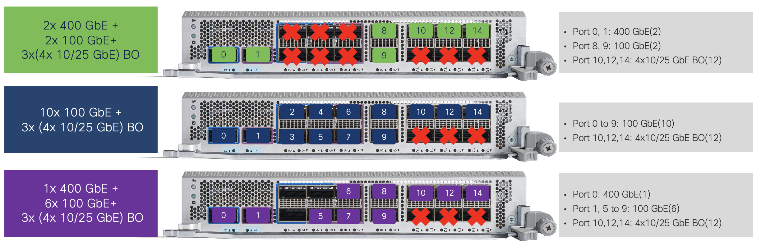
86-MPA-14H2FH-M
This redundant Combo MPA supports 2x QSFPDDs and 14x QSFP28 ports.
This redundant MPA can work with two SC cards with one being active and the other in standby mode. This MPA provides a per slot bandwidth of 1.6 Tbps. The QSFPDD ports can support 40/100/400G optics, the QSFP28 ports can support 40/100G optics. 25G and 10G via breakout cables are also supported.
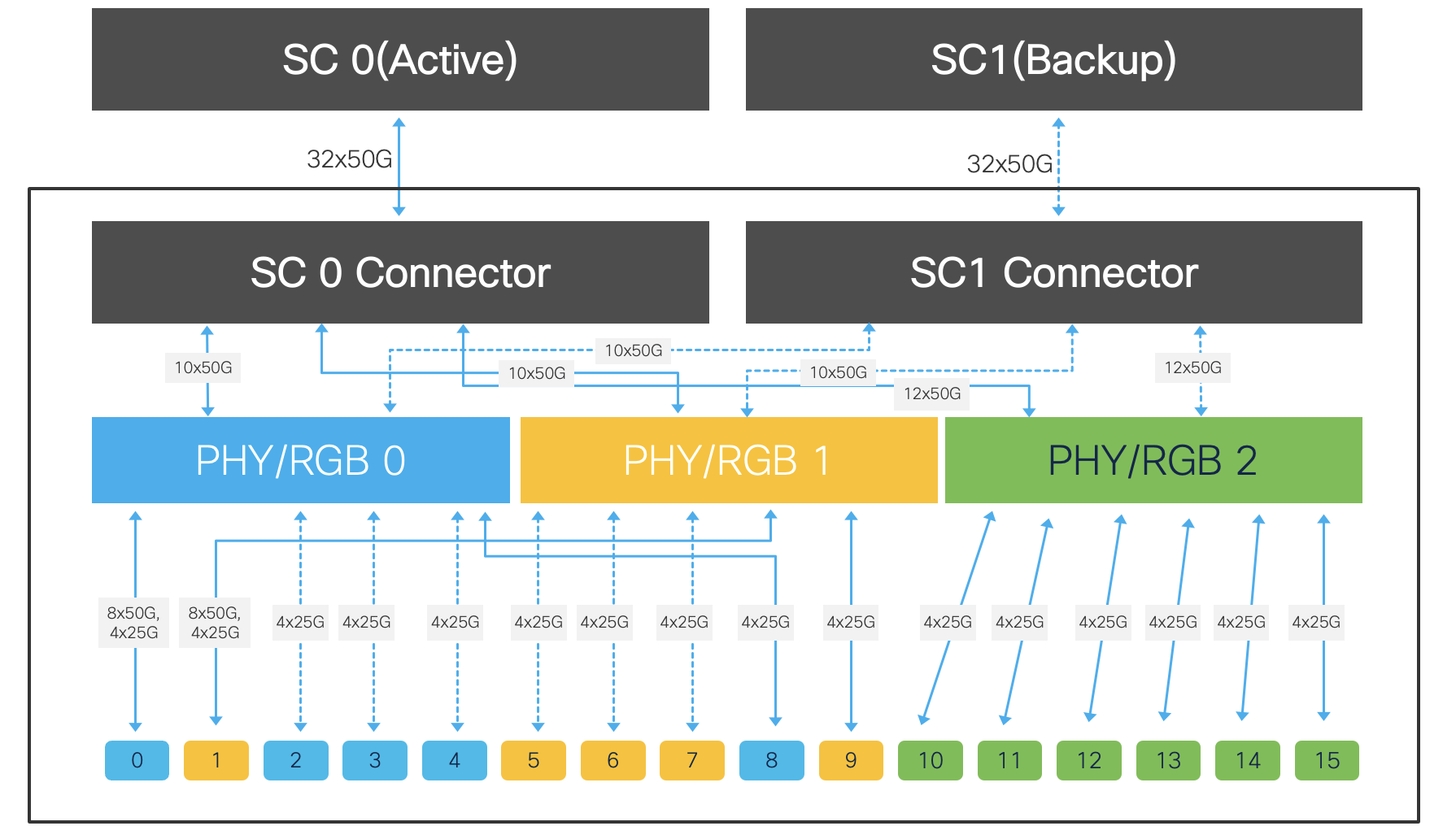
Figure 20. 86-MPA-14H2FH-M Datapath block diagram
This MPA does not have a CPU and is managed by the RP. This each PHY can support the multi-rate Ethernet PHY that provides the capacity and feature integration required to enable MACsec functionality.
86-MPA-14H2FH-M can support several interface combinations.
The first of the combo configurations is 16x100 GbE QSFP, in this configuration the QSFPDD ports are populated with 100G optics not 400G, the QSFP28 ports are populated with 100G optics. This is the default mode(without manual configuration).

The second of the combo configuration is 2x 400G QSFPDD + 8x 100G QSFP, in this configuration the QSFPDD ports are populated with 400G optics.
Changing Port 0 or Port 1 individually to 400G mode automatically disables Port 2/3/4 or Port 5/6/7.
The ports that are available in the 2x 400G QSFPDD + 8x 100G QSFP Combo mode are Ports 0/1/8~15 as shown in the figures below. The faceplate will have markings to reflect this.

The third of the combo configuration is 10/25G breakout solution. 4x 10G or 4x 25G breakout will not be supported on Port 0 to 9 (PHY 0 & 1). Only on PHY 2’s port 10, 12, and 14 and disabled Port 11, 13, and 15.
The following summary is the all scenarios for Native and Breakout solutions on 86-MPA-14H2FH-M MPA.
| Port | Breakout supported | Port Type |
|---|---|---|
| 0 | Yes | (400G Mode) 1x 400 GbE, 4x 100GbE, 2x 100 GbE (Disable Port 2, 3, 4) 1x 100 GbE, 1x 40 GbE, 1x 10 GbE with QSA |
| 1 | Yes | (400G Mode) 1x 400 GbE, 4x 100GbE, 2x 100 GbE (Disable Port 5, 6, 7) 1x 100 GbE, 1x 40 GbE, 1x 10 GbE with QSA |
| 2 | No | 1x 100 GbE, 1 x 40 GbE, 1x 10 GbE with QSA |
| 3 | No | 1x 100 GbE, 1 x 40 GbE, 1x 10 GbE with QSA |
| 4 | No | 1x 100 GbE, 1 x 40 GbE, 1x 10 GbE with QSA |
| 5 | No | 1x 100 GbE, 1 x 40 GbE, 1x 10 GbE with QSA |
| 6 | No | 1x 100 GbE, 1 x 40 GbE, 1x 10 GbE with QSA |
| 7 | No | 1x 100 GbE, 1 x 40 GbE, 1x 10 GbE with QSA |
| 8 | No | 1x 100 GbE, 1 x 40 GbE, 1x 10 GbE with QSA |
| 9 | No | 1x 100 GbE, 1 x 40 GbE, 1x 10 GbE with QSA |
| 10 | Yes | 1x 100 GbE, 1 x 40 GbE, 1x 10 GbE with QSA 4x 25 GbE, 4x 10 GbE (Disable port 11) |
| 11 | No | 1x 100 GbE, 1 x 40 GbE, 1x 10 GbE with QSA |
| 12 | Yes | 1x 100 GbE, 1 x 40 GbE, 1x 10 GbE with QSA 4x 25 GbE, 4x 10 GbE (Disable port 13) |
| 13 | No | 1x 100 GbE, 1 x 40 GbE, 1x 10 GbE with QSA |
| 14 | Yes | 1x 100 GbE, 1 x 40 GbE, 1x 10 GbE with QSA 4x 25 GbE, 4x 10 GbE (Disable port 15) |
| 15 | No | 1x 100 GbE, 1 x 40 GbE, 1x 10 GbE with QSA |
Note: On 86-MPA-14H2FH-M, Port 2 or greater does not support 400G mode CLI
86-MPA-4FH-M
This redundant MPA supports 4x QSFPDD ports. This is a redundant MPA because it can work with two SCs with one being active and the other in standby mode.
This MPA provides a per slot bandwidth of 1.6Tbps. The QSFPDD ports can support 40/100/400G optics and support fully Breakout solutions without any port restriction.
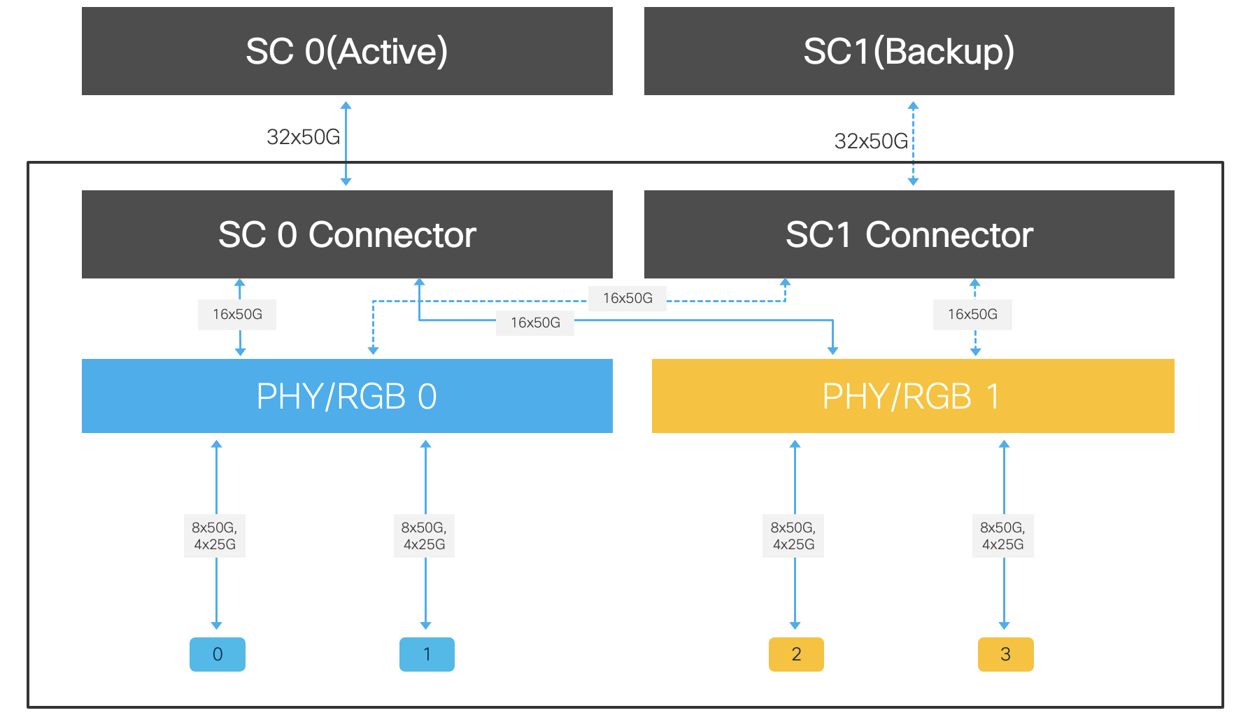
Figure 21. 86-MPA-4FH-M Datapath block diagram
86-MPA-24Z-M
This redundant MPA supports 24x SFP56 ports. This MPA is a redundant MPA because it can work with to two SC with one being active and the other in standby mode.
This MPA provides a per slot bandwidth of 1.2 Tbps. The SFP-1G-LH or SFP-1G-SH ports can support 1 GbE optics without any port restriction. The SFP56 ports can support 10/25G optics and can’t support any Breakout solution.

Figure 22. 86-MPA-24Z-M Datapath block diagram
Note: All even and odd port pair (port 0/1, 2/3, 4/5 … etc) must run at the same speed(both at 10G or both at 25G).
Note: SFP-1G-LH, SFP-1G-SH are supported from XR 24.4.1 onward
To verify optics supported, please use the Cisco Optics-to-Device Compatibility Matrix tool:
the TMG matrix
It contains details on the connector types, the reach, the minimum release required, etc.
Maximum port scale and support on Cisco 8608
The following table represents the maximum number of ports the Cisco 8608 router can support.
| 1 GbE | 10 GbE | 25 GbE | 40 GbE | 50 GbE | 100 GbE | 400 GbE | |
|---|---|---|---|---|---|---|---|
| Native | 192 | 192 | 192 | 128 | 192 | 128 | 32 |
| Breakout | N/S | 128 | 128 | N/A | N/S | 128 | N/A |
N/A: Not applicable – N/S: Not supported
- 1 GbE
- Used with 86-MPA-24Z-M as native with SFP-1G-LH or SFP-1G-SH, fully populated with this MPA into 8 MPAs slots. 8x MPAs and 24x SFP-1G-LH/SFP-1G-SH on each MPA: 192x 1 GbE total
- 10 GbE
- Used with 86-MPA-24Z-M as native with SFP+, fully populated with this MPA into 8 MPAs slots. 8x MPAs and 24x SFP+ on each MPA: 192x 10 GbE total
- Used with 86-MPA-4FH-M as breakout, fully populated with this MPA into 8 MPAs slots. 4x (4x 10 GbE) x 8 MPAs: 128x 10 GbE total
- 25 GbE
- Used with 86-MPA-24Z-M as native with SFP28, fully populated with this MPA into 8 MPAs slots. 8 MPA x 24x SFP28 on each: 192x 25 GbE total
- Use with 86-MPA-4FH-M as breakout, fully populated with this MPA into 8 MPAs slots. 4x (4x 25 GbE) x 8 MPAs: 128x 25 GbE total
- 40 GbE
- Used with 86-MPA-14H2FH-M as native with QSFP+, fully populated with this MPA into 8 MPAs slots. 8 MPAs x 16x QSFP+ on each: 128x 40 GbE total
- 50 GbE
- Not supported at FCS(XR 7.10.1), in the roadmap
- Used with 86-MPA-24Z-M as native with SFP56, fully populated with this MPA into 8 MPAs slots. 8 MPA x 24x SFP56 on each: 192x 50 GbE total
- 100 GbE
- Used with 86-MPA-14H2FH-M as native with QSFP28, fully populated with this MPA into 8 MPAs slots. 8 MPA x 16x QSFP+ on each: 128x 100 GbE total
- Use with 86-MPA-4FH-M as breakout, fully populated with this MPA into 8 MPAs slots. 8 MPAs x 4x (4x 100 GbE) on each: 128x 100 GbE total
- 400 GbE
- Used with 86-MPA-4FH-M as native with QSFPDD, fully populated with this MPA into 8 MPAs slots. 8 MPAs x 4x QSFPDD on each: 32x 400 GbE total
MACsec Support
Starting IOS-XR 7.10.1, MACsec is supported on all ports of Cisco 8608 with all 3 MPAs. All ports are connected to PHY supporting the feature. It can be supported on 10G, 25G, 40G, 100G, 400G ports and also any breakout ports.
- Full line-rate MACsec encryption engines to enable secure and low latency transport
- Supports MACsec GCM-AES-128/256 and GCM-AES-XPN-128/256
- Supports LAN MACsec and WAN MACsec
- Supports “VLAN tag in the clear”

Figure 23. MACsec Use Cases of Cisco 8608
Note: k9 package is required for crypto data plane
Redundancy Details
Within the system even though RP0, RP1, SC0, SC1 are 4 different cards, from redundancy standpoint system software would consider RP0-SC0 together as Active Pair and RP1-SC1 as Standby Pair.
There’s supported and unsupported configuration in Cisco 8608.
| System Type | Supported System configuration | Unsupported System configuration |
|---|---|---|
| Redundant | RP0-SC0, RP1-SC1 | RP0-SC1 RP1-SC0 RP0-SC0, RP1 without SC1 RP1-SC1, RP0 without SC0 |
| Non-Redundant | RP0-SC0, FS1 without RP1 | RP1-SC1 RP1-SC0 RP0-SC1 |
For Redundant 8608, user can use “8608-SYS-R” PID in the order tool. System is shipped with two RPs, two SCs.
For Non-Redundant 8608 configuration, user can use “8608-SYS-NR” PID. 8608 system is shipped with only one RP, one SC, one FS.
Let’s discuss with the default state when system boots up under redundant system.
RP0-SC0 together as one Domain 0(Active Pair) and RP1-SC1 as the other Domain 1(Standby Pair).
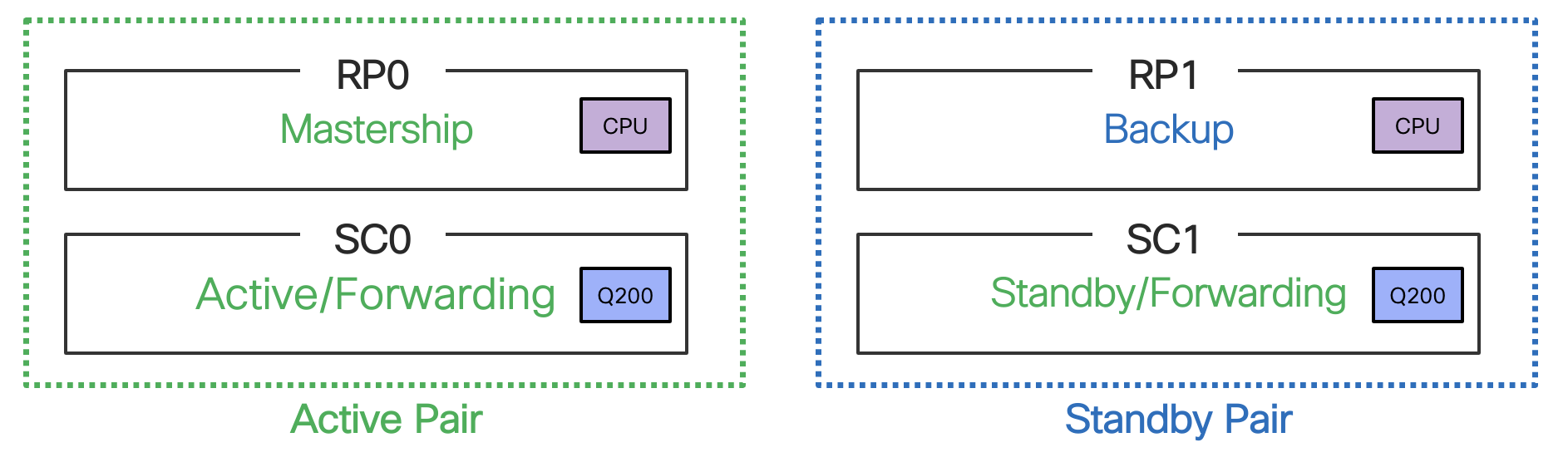
Figure 24. Default Redundant state in Cisco 8608
In this default scenario, RP0 gains mastership and RP1 is in Backup state. Both SC0 and SC1 are packet processing and forwarding capability.
Active/Standby Domain pair can be verified using “show platform domain” CLI.
RP/0/RP0/CPU0:Cisco8608#sh platform domain
ID  Name                Lead           HA Role        State
 --------------------------------------------------------------------------------
1   DOMAIN_RP0_SC0      0/RP0/CPU0     ACTIVE         READY
2   DOMAIN_RP1_SC1      0/RP1/CPU0     STANDBY        READY
Active/Standby Domain pair can be also verified using “show platform domain details” CLI.
RP/0/RP0/CPU0:Cisco8608#sh platform domain  detail
--------------------------------------------------------------------------------
ID   Attribute       Value
--------------------------------------------------------------------------------
1    Name            DOMAIN_RP0_SC0
     Description     Redundancy domain formed together by RP0 and SC0
     State           READY
     HA Role         ACTIVE
     Lead            0/RP0/CPU0
     Member Count    1
     Member          1 : 0/SC0

2    Name            DOMAIN_RP1_SC1
     Description     Redundancy domain formed together by RP1 and SC1
     State           READY
     HA Role         STANDBY
     Lead            0/RP1/CPU0
     Member Count    1
     Member          1 : 0/SC1
If Active RP0 encounters a fatal fault or is removed, Standby RP immediately gains mastership via HW arbitration mechanism. MPAs switchover data path to RP1-SC1.
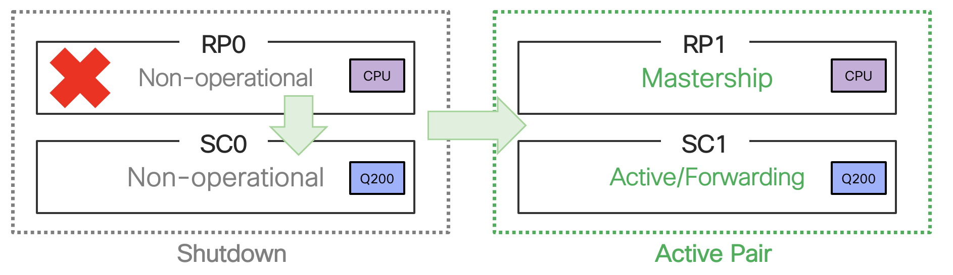
Figure 25. RP0 failure scenario in Cisco 8608
Another scenario is the failure of the SC0 within Active pair, Active RP’s shelfmgr relinquish mastership if standby RP present and ready. Trigger SC reload regardless.
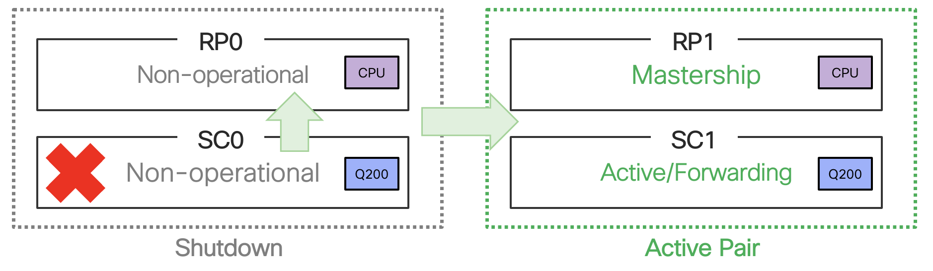
Figure 26. SC0 failure scenario in Cisco 8608
The show platform CLI output will display the Domain states.
RP/0/RP1/CPU0:Cisco8608#sh platform

Node              Type                     State                    Config state
--------------------------------------------------------------------------------
0/RP0/CPU0        8608-RP                  SHUT DOWN                NSHUT
0/RP1/CPU0        8608-RP(Active)          IOS XR RUN               NSHUT
0/SC0             8608-SC0-128             SHUT DOWN                NSHUT
0/SC1             8608-SC0-128             OPERATIONAL              NSHUT
0/FB0             8608-SC0-128[FB]         OPERATIONAL              NSHUT
0/FB1             8608-SC0-128[FB]         OPERATIONAL              NSHUT
~ SNIP ~
Active/Standby Domain pair can be verified using “show platform domain” CLI.
RP/0/RP1/CPU0:Cisco8608#sh platform domain

ID  Name                Lead           HA Role        State
 --------------------------------------------------------------------------------
1   DOMAIN_RP0_SC0      0/RP0/CPU0     STANDBY        NOT_READY
2   DOMAIN_RP1_SC1      0/RP1/CPU0     ACTIVE         READY
Active/Standby Domain pair can be also verified using “show platform domain details” CLI.
RP/0/RP0/CPU0:Cisco8608#sh platform domain  detail
--------------------------------------------------------------------------------
ID   Attribute       Value
--------------------------------------------------------------------------------
1    Name            DOMAIN_RP0_SC0
     Description     Redundancy domain formed together by RP0 and SC0
     State           NOT_READY
     HA Role         STANDBY
     Lead            0/RP0/CPU0
     Member Count    1
     Member          1 : 0/SC0

2    Name            DOMAIN_RP1_SC1
     Description     Redundancy domain formed together by RP1 and SC1
     State           READY
     HA Role         ACTIVE
     Lead            0/RP1/CPU0
     Member Count    1
     Member          1 : 0/SC1
Up to 10 msec traffic drop is expected during active RP/SC Failover. No traffic loss during standby RP/SC reload.
Packet flow in the redundancy system
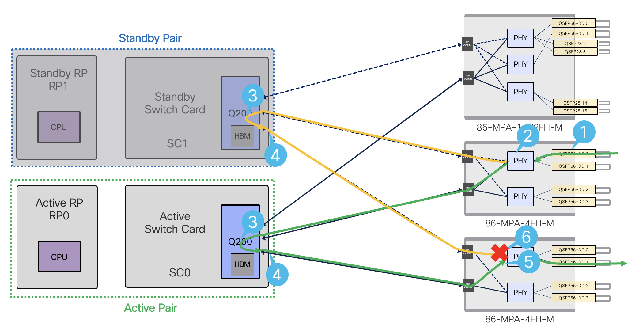
Figure 27. Data path flow with Redundant System.
- Ingress traffic coming from the network into the MPA
- PHY is bi-casted towards Q200s on both Active and Standby Pairs
- Q200s on both active and standby process the received packets
- Both Q200s forward packets towards the MPA that has the destination port
- In the egress path, PHY will forward the packets from active SC0
- PHY will drop packets coming from standby SC1
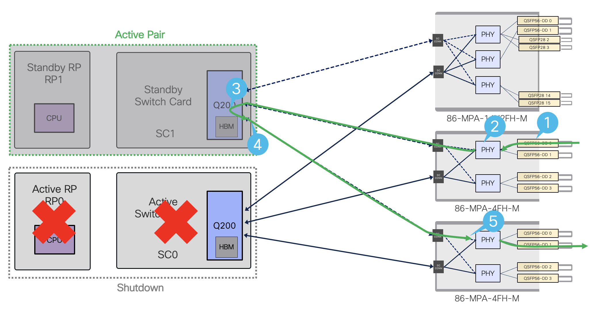
Figure 28. Data path flow after old active pair (RP0/SC0) shutdown
- Ingress traffic coming from the network into the MPA
- PHY is unicasted towards Q200 on new Active Pairs (RP1-SC1)
- Q200 on active SC1 processes the received packets
- Q200 on SC1 forwards packets towards the MPA that has the destination port
- In the egress path, PHY will forward the packets from active SC1
Fan Tray redundancy
8608 provides N+2 Fan Tray redundancy. The system can operate in following conditions:
- 6+2 per redundant system
- 3+1 per Switching Card (SC) or Fan Spinner (FS) for non-redundant systems
In details:
- If active SC has 1 x faulty Fan Tray, system will continue to operate and fan speed will be set to maximum.
- If standby SC has 1 x faulty Fan Tray, system will continue to operate and fan speed will be set to maximum.
- If both active and standby SCs each have 1 x faulty Fan Tray (total of 2 faulty Fan Trays over 8), system will continue to operate and fan speed will be set to maximum.
In the rare case of several Fan Trays failure:
- If active SC0 has 2 x faulty Fan Trays (over 4), the system will perform a switchover to standby SC1. It will also gracefully shutdown the previously active SC0.
- If standby SC1 has 2 x faulty Fan Trays (over 4), the system will gracefully shutdown standby SC1. Same applies if 3 Fan Trays fail.
- If a SC enters in the worst case of 4 x Fan Trays failure, the whole system will gracefully shutdown.
Conclusion
This document discussed the Cisco 8608 architecture.
The Cisco 8608 is a unique platform that combines flexibility & reliability while offering investment protection. Customers can achieve unmatched reliability with redundant control and data plane via redundant Route Processors and Switch cards. Cisco 8608 Switch Cards are based on Cisco Silicon One™ Q200. A wide variety of Modular Port Adapters (MPAs) allow for high interface diversity.
Reference
- Cisco 8608 Datasheet
- Cisco 8608 Hardware Installation Guide
- Cisco 8000 Configuration guide
- Cisco Optics-to-Device Compatibility Matrix tool
- Cisco 8000 MACsec configurations
Modification History
| Version | Data | Author(s) | Comments |
|---|---|---|---|
| 1 | September-8 | Chang Soo Lee | Initial Publication |
| 2 | December-21 | Fred Cuiller | Added Fan Tray redundancy section |
| 3 | December-18 | Chang Soo Lee | Added 1GbE, Port density, and MACsec Use Cases |
Leave a Comment