Cisco 8000 Hardware resources deep dive Part-1: Encapsulation database for label transport
| Ram Mohan A.M., Technical Leader, Technical Marketing ([email protected]) |
| Deepak Balasubramanian, Technical Leader, Technical Marketing ([email protected]) |
Introduction
With Cisco 8000 routers gaining popularity across various service providers and cloud customers, it’s very important to understand how the system behaves when running labelled transport and services. The reason being the labelled applications are hardware resource intensive, especially on the systems built with single stage forwarding architecture.
In this article we will focus on the basic label forwarding transport with & without ECMP along with bundles and look into details on the hardware resource usage. Main focus for this article will be the Encapsulation Database.
Also, in this article we will focus on the Silicon One Q100 and Q200 based 8200/8600/8800 systems only. Resource utilizations for the next generation of Silicon One ASICs (e.g P100) are different and we will have another XR docs article focusing on that.
Cisco 8000 PIDs with Q100/Q200
This table gives the view of current Cisco 8000 products mapping to Q100/Q200
| Forwarding ASICs | Cisco 8000 PIDs |
|---|---|
| Q100 | Standalone: 8201, 8202 , 8800-Line cards: 8800-LC-36FH, 8800-LC-48H |
| Q200 | Standalone: 8201-24H8FH, 8201-32FH, 8202-32FH-M, Centralized 8608 , 8800-Line cards: 88-LC0-36FH(-M), 88-LC0-36H14FH |
When we compare the forwarding ASICs Q100 & Q200, they are very similar in architecture in terms of hardware components and packet forwarding. But there are differences in terms of the number of 50G SerDes links which brings changes in forwarding throughput between the ASICs.
| Q100 | Q200 |
|---|---|
| • 10.8 Tbps | • 12.8 Tbps |
| • 6 Slices with 216 x 50G SerDes | • 6 Slices with 256 x 50G SerDes |
| • 2 x IFG per slice with 18 x 50G SerDes per IFG | • 2 x IFG per slice with 16 x 50G (4 IFGs) or 24 x 50G (8 IFGs) |
| • 36MB on-die packet buffer (SMS) | • 108MB on-die packet buffer (SMS) |
| • 8GB HBM | • 8GB HBM |
Also, there are differences in the hardware resources which will bring in scale differences between the two ASICs.
Hardware resources at high level
Fundamentally, Silicon One ASIC is built with 6 slices where each slice has a set of parallel processing engines for different packet processing functionalities like: IFG - provisions MAC-ports, RxPP – receive packet processor, TxPP- Transmit packet processor and Traffic Manager - VOQs, schedulers.
And number of slices can differ between different ASIC variants keeping fundamental architecture intact.
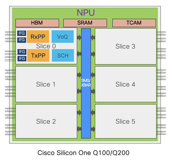
Primarily there are 3 types of hardware memories at a high level,
- TCAM
- SRAM
- HBM
Some of these memories are globally shared across all slices while some are per slice level or slice-pair level. And there are multiple data bases associated with these memories which get accessed at different stages of packet processing.
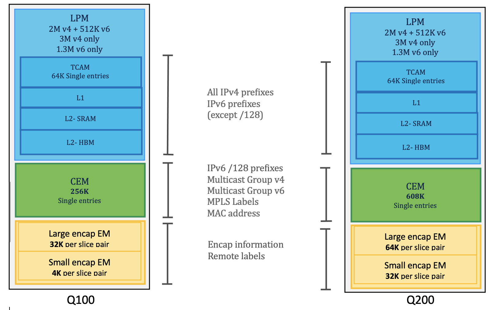
Major database classification is as below,
| Databases | Application |
|---|---|
| LPM | Prefixes storage |
| HBM | LPM FIB table expansion |
| CEM | Prefixes, MACs, local labels etc |
| Egress EMs (Large encap & small encap) | Remote labels for different services labels |
| Stage1lb/Stage2lb: group & members | Next hop groups and ECMP members |
| TCAM | Packet classificaion (ACL,QOS,LPTS) |
Single Stage packet Forwarding: Databases view
What is Single stage forwarding?
Forwarding lookup and all the forwarding decisions are done in the ingress of the packet processor (RxPP) and the packets are properly queued to the VOQ of the corresponding egress interface. In the RxPP during forwarding lookup and resolution, there will be system headers added which have pointers for the encapsulation action on the egress of packet processor (TxPP). Once the packet arrives at the TxPP stage, pointers in the system header will be used to fetch the right encapsulation information (labels, MAC) from the EM database which is used to build the network headers before sending the packets out of the egress interface.
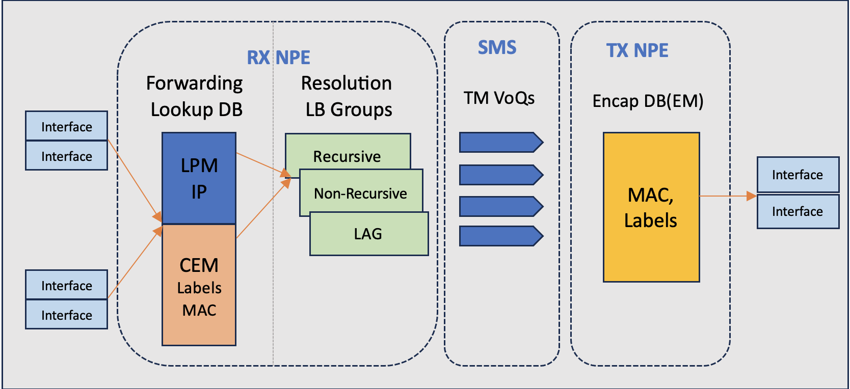
To simplify the flow
- Packet from network interface (NIF) is received by the RX NPE in the ingress.
- Forwarding lookup is done on LPM (IP lookup) or CEM (ex, for labels) and we derive the next hop (NH) and ECMP info.
- LB ECMP group resolution helps to arrive at TM VoQ for the destination port along with egress encap pointers.
- Packets with system headers (carrying encap pointers) are enqueued into the VoQs
- Packets are received on the Tx NPE, system headers are referenced to get the encap pointers in the Encapsulation database to derive the label and the MAC information.
- Packets are reconstructed with proper network headers and send out of the corresponding egress interface.
Understanding Label types & Encapsulation databases
There are 2 types of labels,
- Remote label: label received from remote peer
- It can be transport labels like LDP, SR, RSVP-TE, BGP-LU etc.
- It can be service labels like L3VPN , L2VPN etc.
- Local label: label assigned by the system locally (e.g: per-VRF label, locally allocated LDP)
Remote labels are managed in egress encapsulation (EM) databases and local labels are managed in central exact match (CEM) data bases.
Local labels are looked up from CEM in the ingress termination stage and remote labels are derived from egress encapsulation stage from EM database.
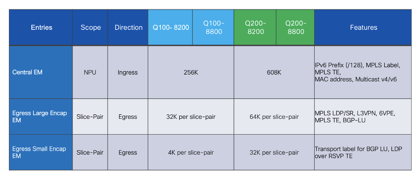
There are 2 types of egress encapsulation databases on Q100/Q200 ASIC based Cisco 8000 systems,
Large Encap DB: Holds MPLS out labels (transport & services) which is the remote label received from remote peer nodes (LDP/SR/RSVP-TE, L2VPN/L3VPN)
Small Encap DB: Holds MPLS remote labels for underlay transport with recursive overlay transport (BGP-LU over LDP/RSVP-TE, LDP over RSVP-TE)
Below table brief on the scope of resource consumption and its scale for Q100 & Q200 based systems,
 (courtesy CS Lee, Cisco)
This write up is about egress large encapsulation resource usage and monitoring
Egress large encap entries can be programmed on a specific slice-pair (LDP, SR) or it can be programmed on all slice-pairs (BGP-LU , L3VPN) of the device depending on the type of labelled applications used.
Egress Large EM on Q100 & Q200 systems
Q100 based systems: The size of large encap table is 32K/slice-pair
- On Standalone systems, this table is divided into three parts, one for each slice-pair. So, each slice-pair has encap table of size 32K(Q100). And total per NPU is 96k
- However, on distributed systems, the NPUs in line cards will have only 3 n/w slices (1.5 slice-pairs) so effectively 64K encap entries exist per NPU.
Q200 based systems: The size of large encap table is 64K/slice pair
- On Standalone system , this table is divided into three parts, one for each slice-pair. So, each slice-pair has encap table of size 64K . And total per NPU is 192K per NPU
- On distributed systems, this table size can go up to 128K per NPU (1.5 slice-pairs).
NOTE:- Though Q200 based system can scale egress large encap upto 192k/128K per NPU on Standalone & distributed systems respectively there is a scale limiting factor comes into play which is Global Resource ID(GRID) which is consumed by every local labels corresponding to the remote labels learned from peer devices. And that limit is ~52K per system. So in essense egress large encap scale also limits to 52K per system.
Lets understand Cisco 8000 slice-pair concept before get into the details of egress large encap resource consumption details,
Slices & Slice-pair concepts
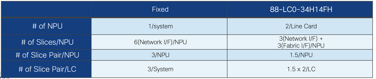
For a Standalone or Centralized systems all 6 slices on the NPU is available for network facing interfaces but same time for a Distributed system only 3 slices are available for network facing interfaces and other 3 slices are used for fabric facing interfaces.
Below pictures depict the slices for Standalone system and distributed system (here representing 88-LC0-34H14FH line card which has 2 NPUs),
 (courtesy CS Lee, Cisco)
Illustration
 (courtesy CS Lee, Cisco)
Standalone systems will have 3 slice-pairs (6 n/w slices) & Distributed systems will have 2 slice-pairs (3 n/w slices)
for Standalone systems,
- If interface belongs to slice # 0,1 then its slice-pair 0
- If interface belongs to slice # 2,3 then its slice-pair 1
- If interface belongs to slice # 4,5 then its slice-pair 2
for distributed systems,
- If interface belongs to slice # 0,1 then its slice-pair 0
- If interface belongs to slice # 2 then its slice-pair 1
Though there are 2 slice pairs avaialable we represent it 1.5 slice pair as there is only one slice associated for slice-pair 1
How to find the interface mapping to NPU/Slice/IFG ?
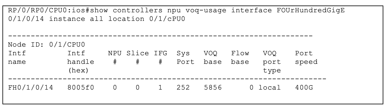
Above example is from a distributed system.
Following illustrations explains how Egress Large encap programming varies for different topologies:
MPLS transport label Scenario without ECMP
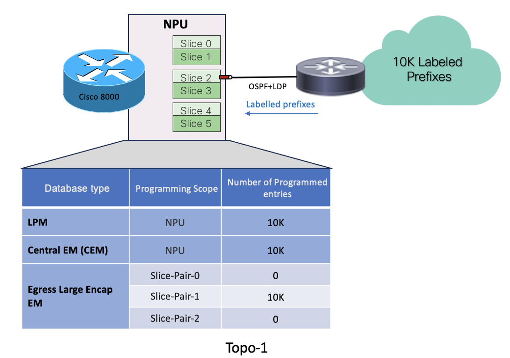
- In Topo-1, the egress interface facing the MPLS cloud is hosted on slice2 (slice-pair1)
- System has received 10k labelled prefixes.
- 10K prefixes get programmed in LPM database.
- Remote labels associated with the prefixes get programmed in egress-large-encap database on the slice-pair, which is hosting the egress interface, here slice-pair1
- Local labels associated with each remote labels get programmed in CEM.
MPLS transport label Scenario with ECMP on same Slice-pair
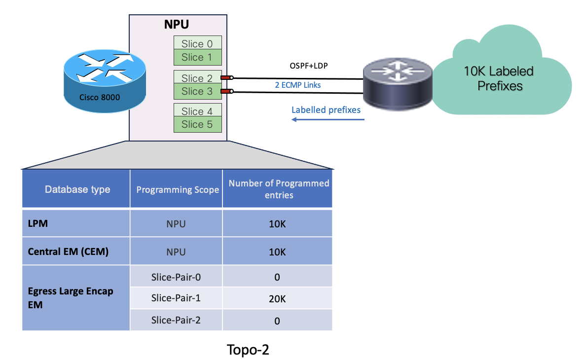
- In Topo-2, System has received 10k labelled prefixes over 2 ECMP links where both links are hosted on same slice-pair (slice-pair1)
- 10K prefixes get programmed in LPM database.
- Remote labels associated with the prefixes get programmed in egress-large-encap database on the slice-pair which is hosting the egress interfaces. So 20k encap entries get programmed on slice-pair1 since there are 2 ECMPs links on that slice-pair.
- Local labels associated with each remote labels get programmed in CEM.
MPLS transport label Scenario with ECMP across different Slice-pairs
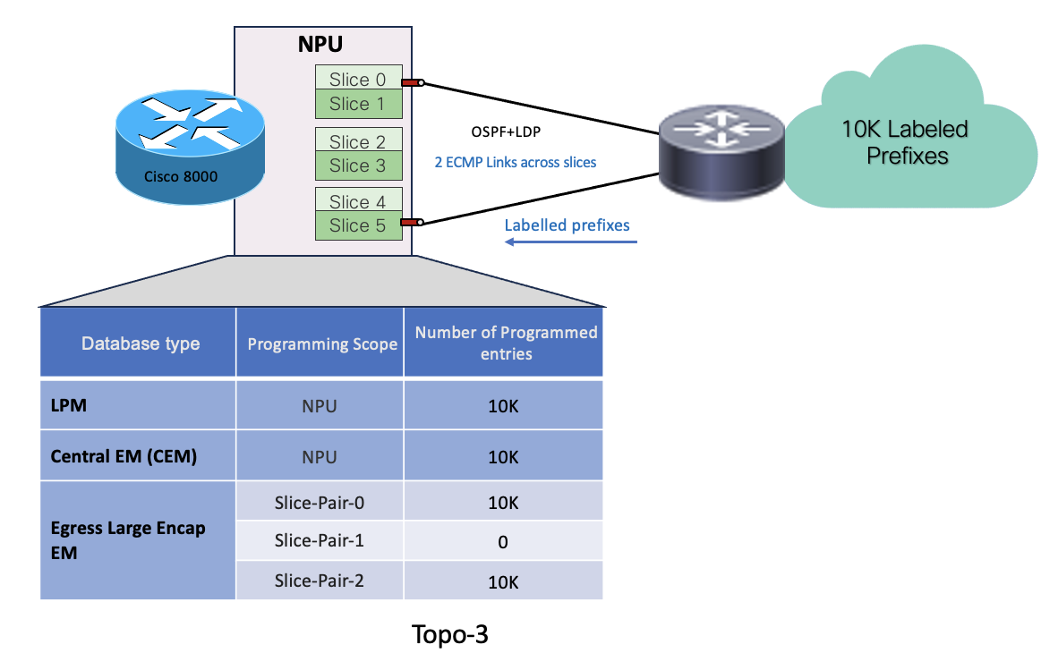
- In Topo-3, System has received 10k labelled prefixes over 2 ECMP links which are spread across 2 different slice-pairs (slice-pair0 & slice-pair2)
- 10K prefixes get programmed in LPM database.
- Remote labels associated with the prefixes get programmed in egress-large-encap database on the slice-pairs which are hosting the egress interfaces. Here there is 1 link each on slice-pair0 & 2. So 10K encap entries get programmed on slice-pair0 & slice-pair2
- Local labels associated with each remote labels get programmed in CEM
MPLS transport label Scenario with Bundle members across different Slice-pairs
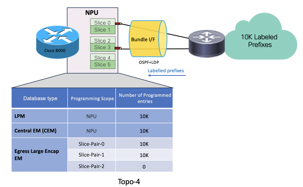
- In Topo-4, System has received 10k labelled prefixes over a bundle interface which has 2 member links distributed across 2 slice-pairs (slice-pair0 & 1)
- 10K prefixes get programmed in LPM database.
- Remote labels associated with the prefixes get programmed in egress-large-encap database on the slice-pairs which is hosting the bundle member links. So 10k encap entries get programmed on each slice-pair0 & 1 .
- Local labels associated with each remote labels get programmed in CEM
MPLS transport label Scenario with Bundle members on same Slice-pair
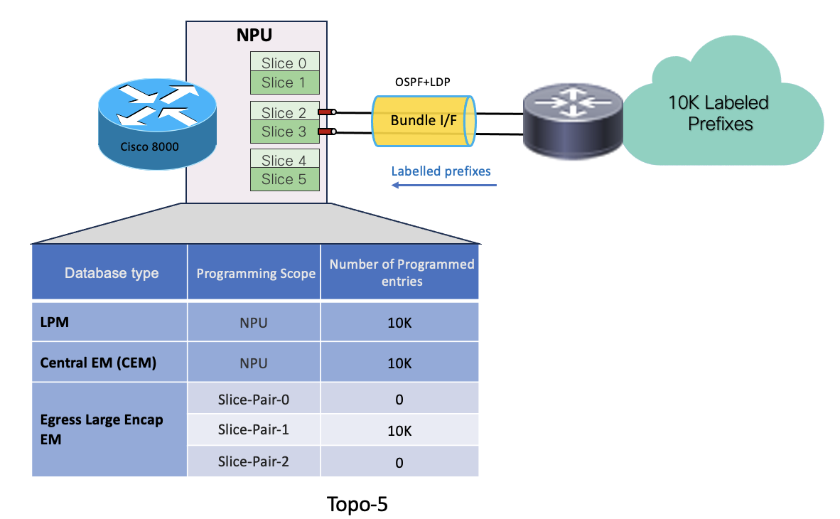
- In Topo-5, System has received 10k labelled prefixes over a bundle interface which has 2 member links hosted on same slice-pair (slice-pair1)
- 10K prefixes get programmed in LPM database.
- Remote labels associated with the prefixes get programmed in egress-large-encap database on the slice-pair which is hosting the bundle member links. So only 10k encap entries get programmed on slice-pair1. Member links from same slice-pair consume single encap entry for each labelled prefix.
- Local labels associated with each remote labels get programmed in CEM
Monitoring labels and encap resources
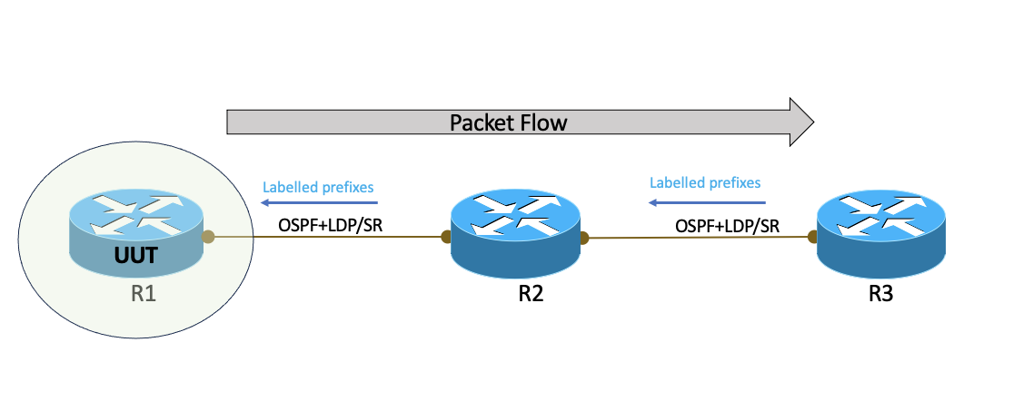
In above topology,
- R1, R2 & R3 from OSPF+LDP or OSPF+SR
- R3 advertise 10k labelled prefixes to R2 and R2 eventually to R1
- R1:R2 link is terminating on slice-pair2 on R1
Resource check on R1(UUT): Before Label advertisement
Lets check the egress encap data base on the UUT (R1) in above topology before R1 received labelled prefixes from R2,
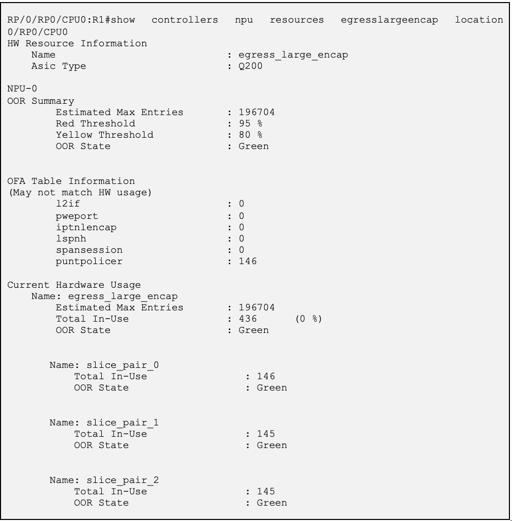
What is seen in the resource table above,
- OOR summary shows the OOR state and threshold levels.
- Egress encap entries for labels are programmed as ‘lspnh’ entries in OFA table. Its zero as this o/p is captured before R1 programmed the entries
- Hardware usage shows the actual HW programmed entries at slice-pair level.
- There are some default entries get programmed in HW as seen above.
Resource check on R1(UUT): After Label advertisement
Let’s advertise 10k labelled prefixes from R3 to R2 over LDP, eventually to R1.
Below output is from R1(UUT) where labelled prefixes are updated in mpls forwarding table as seen below. There are unique outgoing labels for each prefix. There outgoing labels will have egress encap IDs programmed. And there IDs get programmed in egress large encap database. Similarly, there are local labels for each prefixes which get programmed in CEM databased.

Let’s analyse Egress Large Encap resource utilization on R1-UUT ,
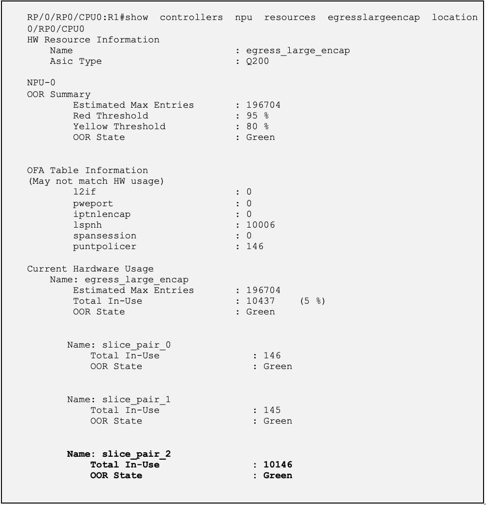
- 10k encap entries are programmed in slice-pair2 (egress interface which is pointing the nexthop is hosted on slice-pair2) in hardware.
- These 10k entries are for outgoing LDP labels. Hence the resource consumption scope is at slice-pair level.
Same label allocation model applies to SR-MPLS transport scenarios as well.
Deployment Recommendations (with labelled transport on Q100/Q200)
- Spread the ECMP links accross different slice-pairs
- Keep the bundle members localized to the same slice pair as much as possible
- LDP allocates label for all prefixes by default so one way to limit lable consumption is by limiting the prefixes itself. So make use of IGP features like ‘advertise pasisve-only’(ISIS) , prefix-suppression(OSPF)
- In case of LDP, allocate labels only for required prefixes by making use of ‘label local advertise’ and ‘allocate-label’ configuration options
This helps optimize the usage of Encapsulation database for labelled transport.
Conclusion
With this we come to the end of this article where we dicussed in details on the harware resource usage with Q100/Q200 for the labelled transport with specific focus on Egress large encapsulation database. In the upcomming articles we will deepdive into other hardware resources and cover different applications.
Leave a Comment