
Cisco 8800 Fan Tray, Fabric Card & Line Card Replacement
Introduction
On a Cisco 8800 router, Fan Tray (FT), Fabric Cards (FC) and Line Cards (LC) are Field Replaceable Units (FRU).
This blog post details the steps required to replace a FT, FC and LC on a Cisco 8800 router. Videos with detailed instructions for FT, FC and LC replacement is also linked in this post below and takes 8818 chassis as an example.
Before Getting Started
Verify the following:
- Line card inserted
show platform - IOS XR version
show install active summary
show install committed summary - FPD status of the cards
show hw-module fpd(should be “CURRENT”)
Fabric Card Replacement
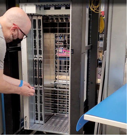
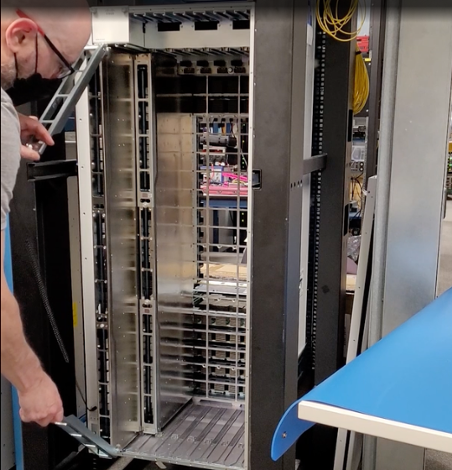
To access a 8800 Fabric Card, Fan Tray must first be removed. 8800 distributed systems use four Fan Trays but can operate with three fan trays while operator replaces one, or temporarily remove one to replace one of the Fabric Cards sitting behind the Fan Tray. When a Fan Tray is removed, the remaining Fan Trays speed up their fans to maintain the designed airflow and target temperature.
Fabric Cards sit behind the Fan Trays on the chassis and the operator must remove Fan Tray unit to replace a Fabric card. Fabric cards mount vertically into the chassis connecting orthogonally to the horizontally placed line cards in the system. Fabric cards utilize ejectors on them to gracefully handle card insertion and removal from the chassis. Ejector handles should be operated properly as directed in this article/video for smooth and uninterrupted functioning of the card in the system.
Video
Step-by-step Procedure
Summary of steps required to replace a FC are as below:
- Shutdown fabric plane.
RP/0/RP0/CPU0:8800(config)#controller fabric plane 0 shutdown
RP/0/RP0/CPU0:8800(config)#commit
RP/0/RP0/CPU0:May 23 22:39:28.824 UTC: fsdbagg[225]: %PKT_INFRA-FM-4-FAULT_MINOR : ALARM_MINOR :FABRIC-PLANE-0 :DECLARE :: Fabric Plane-0 DOWN
RP/0/RP0/CPU0:May 23 22:39:28.824 UTC: fsdbagg[225]: %FABRIC-FSDB_AGG-5-PLANE_UPDOWN : [5117] : Plane 0 state changed to DOWN
RP/0/RP0/CPU0:8800#show controllers fabric plane all
Plane Admin Plane    up->dn  up->mcast
Id    State State    counter   counter
--------------------------------------
0     DN    DN             1         0
1     UP    UP             0         0
2     UP    UP             0         0
3     UP    UP             0         0
4     UP    UP             0         0
5     UP    UP             0         0
6     UP    UP             0         0
7     UP    UP             0         0
RP/0/RP0/CPU0:8800#
Note: Fabric Plane is the term used to describe connection between a line card and a fabric card. There are 8 planes in total into 8800 series routers.
Shutdown fabric card associated to fabric plane.
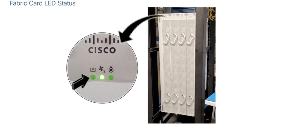
RP/0/RP0/CPU0:8800(config)#hw-module shutdown location 0/FC0 RP/0/RP0/CPU0:8800(config)#commit RP/0/RP0/CPU0:May 23 22:42:13.698 UTC: shelfmgr[240]: %PLATFORM-SHELFMGR-4-CARD_SHUTDOWN : Shutting down 0/FC0: User initiated shutdown from config RP/0/RP0/CPU0:May 23 22:42:13.698 UTC: shelfmgr[240]: %PLATFORM-SHELFMGR-6-INFO_LOG : 0/FC0 is shutdown RP/0/RP0/CPU0:8800#show platform Node Type State Config state -------------------------------------------------------------------------------- 0/RP0/CPU0 8800-RP(Active) IOS XR RUN NSHUT 0/RP0/BMC0 8800-RP OPERATIONAL NSHUT 0/0/CPU0 8800-LC-48H IOS XR RUN NSHUT 0/FC0 8808-FC SHUT DOWN SHUT 0/FC1 8808-FC OPERATIONAL NSHUT- Verify Fabric Card LED is turned Off.
- Unscrew FAN tray
- Remove Fan Tray corresponding to the fabric card which needs to be replaced.
- Insert Fabric card rail extension.
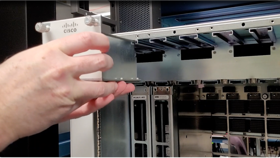 Note: At the time of publishing this video, the fabric card rail extension is only available on 8818 routers. 8804, 8808 and 8812 chassis do not need fabric card rail extension.
 - Loosen both the ejector handles on fabric card.
- Pull the FC out of the chassis using both ejector handles.
- Insert replacement fabric card.
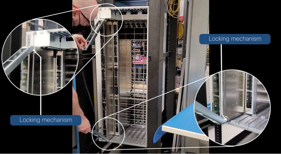
- Tighten both the ejector handles on the new fabric card.
- Remove fabric card rail extension.
- Install Fan tray.
- Unshut fabric card.
RP/0/RP0/CPU0:8800(config)#no hw-module shutdown location 0/FC0 RP/0/RP0/CPU0:8800(config)#commit RP/0/RP0/CPU0:May 23 22:45:02.113 UTC: shelfmgr[240]: %PLATFORM-SHELFMGR-4-CARD_RELOAD : Reloading 0/FC0: User initiated no-shutdown from config RP/0/RP0/CPU0:ios#RP/0/RP0/CPU0:May 23 22:45:34.435 UTC: shelfmgr[240]: %PLATFORM-SHELFMGR-6-INFO_LOG : 0/FC0 is operational RP/0/RP0/CPU0:ios#show platform Node Type State Config state -------------------------------------------------------------------------------- 0/RP0/CPU0 8800-RP(Active) IOS XR RUN NSHUT 0/RP0/BMC0 8800-RP OPERATIONAL NSHUT 0/0/CPU0 8800-LC-48H IOS XR RUN NSHUT 0/FC0 8808-FC OPERATIONAL NSHUT 0/FC1 8808-FC OPERATIONAL NSHUT - Unshut fabric plane.
RP/0/RP0/CPU0:8800(config)#no controller fabric plane 0 shutdown
RP/0/RP0/CPU0:8800(config)#commit
RP/0/RP0/CPU0:May 23 22:47:09.904 UTC: fsdbagg[225]: %FABRIC-FSDB_AGG-5-PLANE_UPDOWN : [5117] : Plane 0 state changed to UP
RP/0/RP0/CPU0:ios#show controllers fabric plane all
Plane Admin Plane    up->dn  up->mcast
Id    State State    counter   counter
--------------------------------------
0     UP    UP             1         0
1     UP    UP             0         0
2     UP    UP             0         0
3     UP    UP             0         0
4     UP    UP             0         0
5     UP    UP             0         0
6     UP    UP             0         0
7     UP    UP             0         0
RP/0/RP0/CPU0:8800#
Note: Too ensure proper airflow and prevent overheating, do not operate the router with three fan trays for more than 10 minutes. 8800 routers can work with 3 FTs and operates in N+1 redundancy model. If the replacement fan tray is not ready, faulty FT must remain in the chassis.
Line Card Replacement
Line cards on 8800 chassis are available in two variants with respect to the ejector functionality.
- LC Type 1: Ejector Levers with Buttons. 8800-LC-48H, 8800-LC-36FH
- LC Type 2: Ejector Levers with Latches. 88-LC0-34H14FH, 88-LC0-36FH, 88-LC0-36FH-M, 88-LC1-36EH

Line cards have two ejector levers to release the card from the router. Use these levers to remove the line card and to seat the line card firmly in the router when line card is installed. The ejector levers align and seat the card connectors in the router. To avoid damaging card mechanical components, never carry a line card by the captive installation screws or ejector levers. Doing so can damage these components and cause card insertion problems.
Opening the ejector levers of an installed line card causes the line card to shut down even when the captive screws are screwed in. To reboot the line card, users must do one of the following:
- Remove and reinsert the line card and close the ejector levers.
- Close the ejector levers and reload the card using the
reload location 0/line-card-slot forcecommand.
Video
Line Card Removal
Run the
shutdown location 0/linecard-slot/CPU0command, which gracefully shuts down the line card.RP/0/RP0/CPU0:8812-1#shutdown location 0/1 0/1/CPU0 0/1 RP/0/RP0/CPU0:8812-1#shutdown location 0/1/CPU0 Proceed with shutdown? [confirm] RP/0/RP0/CPU0:Jul 11 13:27:26.611 UTC: shelfmgr_exec_cli[66474]: %PLATFORM-SHELFMGR-6-USER_OP : User root requested 'graceful card shutdown' of 0/1/CPU0 RP/0/RP0/CPU0:Jul 11 13:27:26.619 UTC: fsdbagg[157]: %PKT_INFRA-FM-4-FAULT_MINOR : ALARM_MINOR :FABRIC-PLANE-0 :DECLARE :: Fabric Plane-0 DOWN RP/0/RP0/CPU0:Jul 11 13:27:26.619 UTC: fsdbagg[157]: %FABRIC-FSDB_AGG-5-PLANE_UPDOWN : [6260] : Plane 0 state changed to DOWN RP/0/RP0/CPU0:Jul 11 13:27:26.623 UTC: fsdbagg[157]: %PKT_INFRA-FM-4-FAULT_MINOR : ALARM_MINOR :FABRIC-PLANE-1 :DECLARE :: Fabric Plane-1 DOWN RP/0/RP0/CPU0:Jul 11 13:27:26.623 UTC: fsdbagg[157]: %FABRIC-FSDB_AGG-5-PLANE_UPDOWN : [6260] : Plane 1 state changed to DOWN RP/0/RP0/CPU0:Jul 11 13:27:26.625 UTC: fsdbagg[157]: %PKT_INFRA-FM-4-FAULT_MINOR : ALARM_MINOR :FABRIC-PLANE-2 :DECLARE :: Fabric Plane-2 DOWN RP/0/RP0/CPU0:Jul 11 13:27:26.625 UTC: fsdbagg[157]: %FABRIC-FSDB_AGG-5-PLANE_UPDOWN : [6260] : Plane 2 state changed to DOWN RP/0/RP0/CPU0:Jul 11 13:27:26.628 UTC: fsdbagg[157]: %PKT_INFRA-FM-4-FAULT_MINOR : ALARM_MINOR :FABRIC-PLANE-3 :DECLARE :: Fabric Plane-3 DOWN RP/0/RP0/CPU0:Jul 11 13:27:26.628 UTC: fsdbagg[157]: %FABRIC-FSDB_AGG-5-PLANE_UPDOWN : [6260] : Plane 3 state changed to DOWN RP/0/RP0/CPU0:Jul 11 13:27:26.629 UTC: fsdbagg[157]: %PKT_INFRA-FM-4-FAULT_MINOR : ALARM_MINOR :FABRIC-PLANE-4 :DECLARE :: Fabric Plane-4 DOWN RP/0/RP0/CPU0:Jul 11 13:27:26.629 UTC: fsdbagg[157]: %FABRIC-FSDB_AGG-5-PLANE_UPDOWN : [6260] : Plane 4 state changed to DOWN LC/0/1/CPU0:Jul 11 13:27:26.629 UTC: npu_drvr[227]: %PLATFORM-VETH_PD-2-RX_FAULT : Interface FourHundredGigE0_1_0_9, Detected Local Fault RP/0/RP0/CPU0:Jul 11 13:27:26.630 UTC: fsdbagg[157]: %PKT_INFRA-FM-4-FAULT_MINOR : ALARM_MINOR :FABRIC-PLANE-5 :DECLARE :: Fabric Plane-5 DOWN RP/0/RP0/CPU0:Jul 11 13:27:26.630 UTC: fsdbagg[157]: %FABRIC-FSDB_AGG-5-PLANE_UPDOWN : [6260] : Plane 5 state changed to DOWN RP/0/RP0/CPU0:Jul 11 13:27:26.631 UTC: fsdbagg[157]: %PKT_INFRA-FM-4-FAULT_MINOR : ALARM_MINOR :FABRIC-PLANE-6 :DECLARE :: Fabric Plane-6 DOWN RP/0/RP0/CPU0:Jul 11 13:27:26.631 UTC: fsdbagg[157]: %FABRIC-FSDB_AGG-5-PLANE_UPDOWN : [6260] : Plane 6 state changed to DOWN RP/0/RP0/CPU0:Jul 11 13:27:26.632 UTC: fsdbagg[157]: %PKT_INFRA-FM-4-FAULT_MINOR : ALARM_MINOR :FABRIC-PLANE-7 :DECLARE :: Fabric Plane-7 DOWN RP/0/RP0/CPU0:Jul 11 13:27:26.632 UTC: fsdbagg[157]: %FABRIC-FSDB_AGG-5-PLANE_UPDOWN : [6260] : Plane 7 state changed to DOWN LC/0/1/CPU0:Jul 11 13:27:28.552 UTC: obflmgr[172]: %PLATFORM-OBFL-6-INFO : Unmounted OBFL directory for 0/1/CPU0 LC/0/1/CPU0:Jul 11 13:27:29.814 UTC: esd[151]: %INFRA-ESD-6-SIGNAL_RCV : ESD received signal 1 LC/0/1/CPU0:Jul 11 13:27:29.814 UTC: esd[151]: %INFRA-ESD-6-PROCESS_EXIT : ESD process is exiting, reason 0x1, normal shutdown RP/0/RP1/CPU0:Jul 11 13:27:30.449 UTC: esdma[127]: %PKT_INFRA-FM-4-FAULT_MINOR : ALARM_MINOR :ESDMA-ESD-CONN-ERR :DECLARE :0/LC1/LC_SW: RP/0/RP0/CPU0:Jul 11 13:27:30.449 UTC: esdma[265]: %PKT_INFRA-FM-4-FAULT_MINOR : ALARM_MINOR :ESDMA-ESD-CONN-ERR :DECLARE :0/LC1/LC_SW: RP/0/RP1/CPU0:Jul 11 13:27:35.238 UTC: esd[174]: %INFRA-ESD-6-PORT_STATE_CHANGE_LINK_DOWN : The physical link state of the control ethernet switch port 0 has changed. New Link state DOWN, Admin state: UP RP/0/RP0/CPU0:Jul 11 13:27:35.238 UTC: esd[294]: %INFRA-ESD-6-PORT_STATE_CHANGE_LINK_DOWN : The physical link state of the control ethernet switch port 0 has changed. New Link state DOWN, Admin state: UP RP/0/RP0/CPU0:Jul 11 13:27:35.338 UTC: shelfmgr[212]: %PLATFORM-SHELFMGR-4-CARD_SHUTDOWN : Shutting down 0/1/CPU0: User initiated card shutdown RP/0/RP0/CPU0:Jul 11 13:27:35.339 UTC: shelfmgr[212]: %PLATFORM-SHELFMGR-6-INFO_LOG : 0/1/CPU0 is shutdown RP/0/RP0/CPU0:Jul 11 13:27:35.343 UTC: envmon[397]: %PKT_INFRA-FM-3-FAULT_MAJOR : ALARM_MAJOR :Power reservation exceeds available power :CLEAR :0:Note: It’s also possible to shutdown a line card using following XR config
shutdown location 0/linecard-slot/CPU0. To boot the linecard, use theno shutdown location 0/linecard-slot/CPU0configuration.- Verify that the Line Card LED for the slot that you specified turns off. Also, you can use the show platform command to verify that the status of the card is SHUT DOWN.
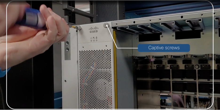
RP/0/RP0/CPU0:8812-1#show platform Node Type State Config state -------------------------------------------------------------------------------- 0/RP0/CPU0 8800-RP(Active) IOS XR RUN NSHUT 0/RP1/CPU0 8800-RP(Standby) IOS XR RUN NSHUT 0/1/CPU0 88-LC0-36FH SHUT DOWN NSHUT 0/FC0 8812-FC OPERATIONAL NSHUT 0/FC1 8812-FC OPERATIONAL NSHUT 0/FC2 8812-FC OPERATIONAL NSHUT 0/FC3 8812-FC OPERATIONAL NSHUT 0/FC4 8812-FC OPERATIONAL NSHUT 0/FC5 8812-FC OPERATIONAL NSHUT 0/FC6 8812-FC OPERATIONAL NSHUT 0/FC7 8812-FC OPERATIONAL NSHUT 0/FT0 8812-FAN OPERATIONAL NSHUT 0/FT1 8812-FAN OPERATIONAL NSHUT 0/FT2 8812-FAN OPERATIONAL NSHUT 0/FT3 8812-FAN OPERATIONAL NSHUT 0/PT0 8800-HV-TRAY OPERATIONAL NSHUT 0/PT1 8800-HV-TRAY OPERATIONAL NSHUT 0/PT2 8800-HV-TRAY OPERATIONAL NSHUT - Loosen the two captive screws.
- Ejectors
- LC Type1: Press the ejector buttons to open two ejector levers.
- LC Type2: Slide the ejector lever latches outward and pull the two ejector levers.
- Use the ejector levers to pull the line card a couple of inches (about 5 cm) from the chassis.
- Close the ejector levers. Use one hand to hold the front of the line card, place your other hand under the line card to support its weight, pull it out of the chassis, and set it on an antistatic surface or inside an antistatic bag.
Line Card Insertion
- Align the back of the line card to the guides in the open line card slot and slide the line card all the way into the slot.
- The line card stops when its front is about 0.25 inches (0.6 cm) outside the front of the chassis.
- Ejectors
- LC Type1: Press the ejector buttons, and the two levers move partway from the center of the line card.
- LC Type2: Slide the ejector lever latches to unlock the ejector levers and open the ejector levers outward.
- Close the ejectors by rotating the ends of the two levers toward the center of the chassis.
- Tighten the two captive screws. (Fully tighten both captive installation screws to ensure that the card is correctly seated in the router. A card that is only partially seated in the router might not operate properly, even if it boots.)
- Attach each interface cable to the appropriate port on the line card. Use the label on each cable to determine which port each cable attaches to.
Run the
reload location 0/linecard-slot/CPU0command, which gracefully reboots the line card.RP/0/RP0/CPU0:8812-1#reload location 0/1/CPU0 Proceed with reload? [confirm] RP/0/RP0/CPU0:Jul 11 13:51:52.464 UTC: shelfmgr_exec_cli[67628]: %PLATFORM-SHELFMGR-6-USER_OP : User root requested graceful card reload of 0/1/CPU0 RP/0/RP0/CPU0:8812-1#RP/0/RP0/CPU0:Jul 11 13:51:52.475 UTC: shelfmgr[212]: %PLATFORM-SHELFMGR-4-CARD_RELOAD : Reloading 0/1/CPU0: User initiated card reload - snip - RP/0/RP0/CPU0:Jul 11 13:55:52.040 UTC: shelfmgr[212]: %PLATFORM-SHELFMGR-6-INFO_LOG : 0/1/CPU0 is operational RP/0/RP0/CPU0:8812-1#show platform Node Type State Config state -------------------------------------------------------------------------------- 0/RP0/CPU0 8800-RP(Active) IOS XR RUN NSHUT 0/RP1/CPU0 8800-RP(Standby) IOS XR RUN NSHUT 0/1/CPU0 88-LC0-36FH IOS XR RUN NSHUT 0/FC0 8812-FC OPERATIONAL NSHUT 0/FC1 8812-FC OPERATIONAL NSHUT 0/FC2 8812-FC OPERATIONAL NSHUT 0/FC3 8812-FC OPERATIONAL NSHUT 0/FC4 8812-FC OPERATIONAL NSHUT 0/FC5 8812-FC OPERATIONAL NSHUT 0/FC6 8812-FC OPERATIONAL NSHUT 0/FC7 8812-FC OPERATIONAL NSHUT 0/FT0 8812-FAN OPERATIONAL NSHUT 0/FT1 8812-FAN OPERATIONAL NSHUT 0/FT2 8812-FAN OPERATIONAL NSHUT 0/FT3 8812-FAN OPERATIONAL NSHUT 0/PT0 8800-HV-TRAY OPERATIONAL NSHUT 0/PT1 8800-HV-TRAY OPERATIONAL NSHUT 0/PT2 8800-HV-TRAY OPERATIONAL NSHUT- Verify that the line card LEDs turn on and appear green.
- Check line card Field Programmble Devices (FPD) version. While FPD auto-upgrade is enabled by default, line card must be manually reloaded to make it effective unless
fpd auto-reload enablefeature is used. For more information, please refer to Cisco 8000 FPD DocumentationRP/0/RP0/CPU0:8812-1#sh hw-module fpd Auto-upgrade:Enabled Attribute codes: B golden, P protect, S secure FPD Versions ============== Location Card type HWver FPD device ATR Status Running Programd Reload Loc ------------------------------------------------------------------------------------------------- 0/1/CPU0 88-LC0-36FH 0.34 Bios S CURRENT 1.03 1.03 0/1/CPU0 0/1/CPU0 88-LC0-36FH 0.34 BiosGolden BS NEED UPGD 0.09 0/1/CPU0 0/1/CPU0 88-LC0-36FH 0.34 EthSwitch CURRENT 1.04 1.04 0/1 0/1/CPU0 88-LC0-36FH 0.34 EthSwitchGolden B P CURRENT 1.02 0/1 0/1/CPU0 88-LC0-36FH 0.34 IoFpga NOT READY 0.128 0.128 N/A 0/1/CPU0 88-LC0-36FH 0.34 IoFpgaGolden B NEED UPGD 0.128 0/1 0/1/CPU0 88-LC0-36FH 0.34 SsdIntelS4510 S NEED UPGD 11.32 11.32 0/1 0/1/CPU0 88-LC0-36FH 0.34 x86Fpga S CURRENT 1.15 1.15 0/1 0/1/CPU0 88-LC0-36FH 0.34 x86FpgaGolden BS CURRENT 1.04 0/1 0/1/CPU0 88-LC0-36FH 0.34 x86TamFw S CURRENT 6.05 6.05 0/1 0/1/CPU0 88-LC0-36FH 0.34 x86TamFwGolden BS CURRENT 6.05 0/1 - To manually upgrade a line card FPDs, use following command:
upgrade hw-module location 0/linecard-location/CPU0 fpd all
General Verification
show shelfmgr history oir
show inventory
show proc cpu
show environment all
show led
show alarms
show controller fabric health
show controllers fabric plane all statistics
show hw-module fpd
Conclusion
This concludes the steps required for replacement of FT, FC and LC on 8800 system. Following meticulously to the outlined steps provided in this document will result in smooth operations.
Leave a Comment