
Metro Fabric High Level Design
Value Proposition
Service Providers are facing the challenge to provide next generation services that can quickly adapt to market needs. New paradigms such as 5G introduction, video traffic continuous growth, IoT proliferation and cloud services model require unprecedented flexibility, elasticity and scale from the network. Increasing bandwidth demands and decreasing ARPU put pressure on reducing network cost. At the same time, services need to be deployed faster and more cost effectively to stay competitive.
Metro Access and Aggregation solutions have evolved from native Ethernet/Layer 2 based, to Unified MPLS to address the above challenges. The Unified MPLS architecture provides a single converged network infrastructure with a common operational model. It has great advantages in terms of network convergence, high scalability, high availability, and optimized forwarding. However, that architectural model is still quite challenging to manage, especially on large-scale networks, because of the large number of distributed network protocols involved which increases operational complexity.
Compass Metro Fabric (CMF) design introduces an SDN-ready architecture which evolves traditional Metro network design towards an SDN enabled, programmable network capable of delivering all services (Residential, Business, 5G Mobile Backhauling, Video, IoT) on the premise of simplicity, full programmability, and cloud integration, with guaranteed service level agreements (SLAs).

The Compass Metro Fabric design brings tremendous value to the Service Providers:
Fast service deployment and rapid time to market through fully automated service provisioning and end-to-end network programmability
Operational simplicity with less protocols to operate and manage
Smooth migration towards an SDN-ready architecture thanks to backward-compatibility with existing network protocols and services
Next generation services creation leveraging guaranteed SLAs
Enhanced and optimized operations using telemetry/analytics in conjunction with automation tools
The Compass Metro Fabric design is targeted at Service Provider customers who:
Want to evolve their existing Unified MPLS Network
Are looking for an SDN ready solution
Need a simple, scalable design that can support future growth
Want an industry–leading or future proof technology and architecture
Summary
The Compass Metro Fabric design meets the criteria identified for compass designs:
Simple: based on Segment Routing as unified forwarding plane and EVPN and L3VPN as a common BGP based control plane
Programmable: it uses SR-PCE to program end-to-end paths across the network with guaranteed SLAs
Automatable: service provisioning is fully automated using NSO and Yang models; analytics with model driven telemetry in conjunction with automation tools will be used in the future to enhance operations and network and services optimization
Repeatable: it’s an evolution of the Unified MPLS architecture and based on standard protocols
Technical Overview
The Compass Metro Fabric design evolves from the successful Cisco Evolved Programmable Network (EPN) 5.0 architecture framework, to bring greater programmability and automation.
In the Compass Metro Fabric design, the transport and service are built on-demand when the customer service is requested. The end-to-end inter-domain network path is programmed through controllers and selected based on the customer SLA, such as the need for a low latency path.
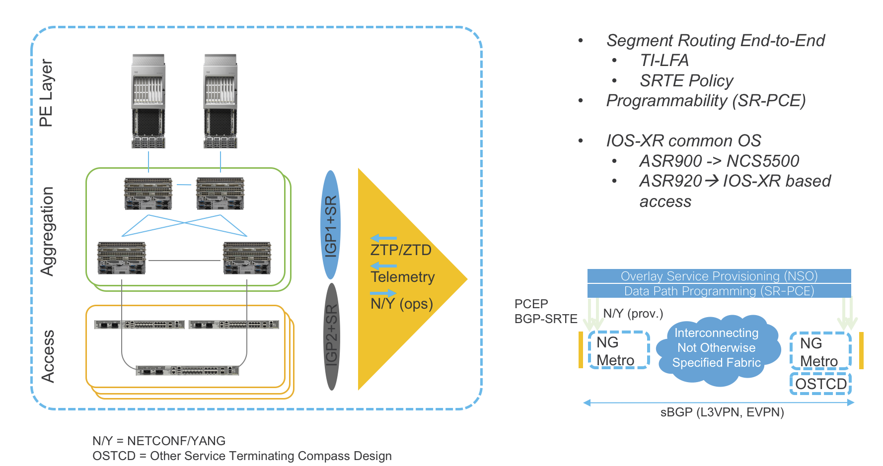
The Compass Metro Fabric is made of the following main building blocks:
IOS-XR as a common Operating System proved in Service Provider Networks
Transport Layer based on Segment Routing as Unified Forwarding Plane
SDN - Segment Routing Path Computation Element (SR-PCE) as Cisco Path Computation Engine (PCE) coupled with Segment Routing to provide simple and scalable inter-domain transport connectivity and Traffic Engineering and Path control
Service Layer for Layer 2 (EVPN) and Layer 3 VPN services based on BGP as Unified Control Plane
Automation and Analytics
NSO for service provisioning
Netconf/YANG data models
Telemetry to enhance and simplify operations
Zero Touch Provisioning and Deployment (ZTP/ZTD)
By leveraging analytics collected through model driven telemetry on IOS-XR platforms, in conjunction with automation tools, Compass Metro Fabric provides Service Providers with enhancements in network and services operations experience.
Transport – Design
Use Cases
Service Provider networks must adopt a very flexible design that satisfy any to any connectivity requirements, without compromising in stability and availability. Moreover, transport programmability is essential to bring SLA awareness into the network,
The goals of the Compass Metro Fabric is to provide a flexible network blueprint that can be easily customized to meet customer specific requirements.
To provide unlimited network scale, the Compass Metro Fabric is structured into multiple IGP Domains: Access, Aggregation, and Core. Refer to the network topology in Figure 1.
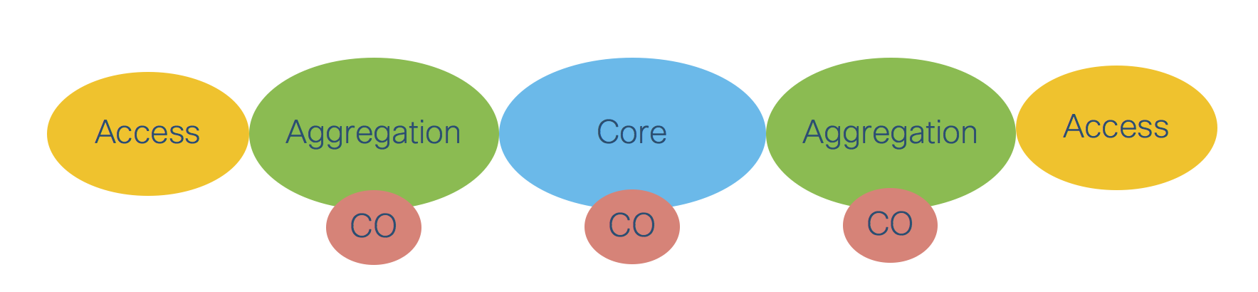
Figure 1: Distributed Central Office
The network diagram in Figure 2 shows how a Service Provider network can be simplified by decreasing the number of IGP domains. In this scenario the Core domain is extended over the Aggregation domain, thus increasing the number of nodes in the Core.
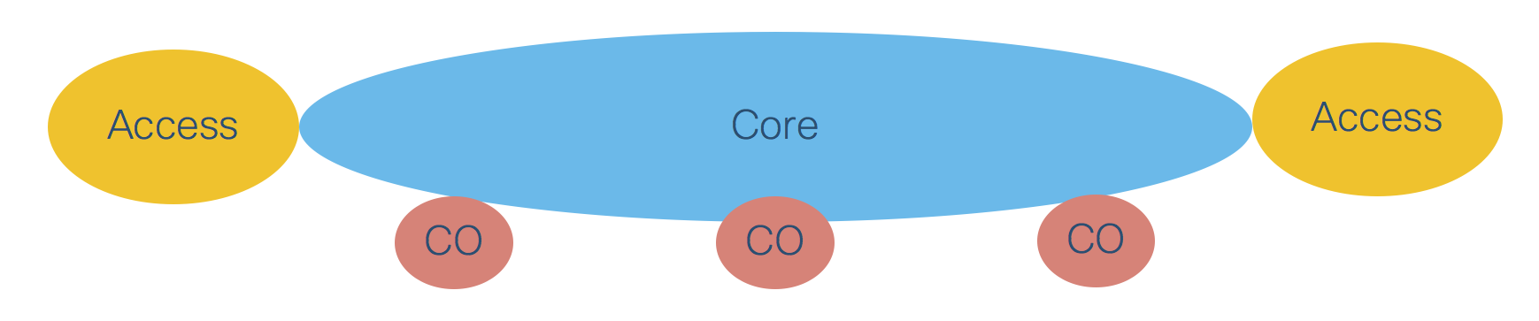 Figure 2: Distributed Central Office with Core domain extension
A similar approach is shown in Figure 3. In this scenario the Core domain remains unaltered and the Access domain is extended over the Aggregation domain, thus increasing the number of nodes in the Access domain.

Figure 3: Distributed Central Office with Access domain extension
The Compass Metro Fabric transport design supports all three network options, while remaining easily customizable.
The first phase of the Compass Metro Fabric, discussed later in this document, will cover in depth the scenario described in Figure 3.
Intra-Domain
Intra-Domain Routing and Forwarding
The Compass Metro Fabric is based on a fully programmable transport that satisfies the requirements described earlier. The foundation technology used in the transport design is Segment Routing (SR) with a MPLS based Data Plane in Phase 1 and a IPv6 based Data Plane (SRv6) in future.
Segment Routing dramatically reduces the amount of protocols needed in a Service Provider Network. Simple extensions to traditional IGP protocols like ISIS or OSPF provide full Intra-Domain Routing and Forwarding Information over a label switched infrastructure, along with High Availability (HA) and Fast Re-Route (FRR) capabilities.
Segment Routing defines the following routing related concepts:
Prefix-SID – A node identifier that must be unique for each node in a IGP Domain. Prefix-SID is statically allocated by th3 network operator.
Adjacency-SID – A node’s link identifier that must be unique for each link belonging to the same node. Adjacency-SID is typically dynamically allocated by the node, but can also be statically allocated.
In the case of Segment Routing with a MPLS Data Plane, both Prefix-SID and Adjacency-SID are represented by the MPLS label and both are advertised by the IGP protocol. This IGP extension eliminates the need to use LDP or RSVP protocol to exchange MPLS labels.
The Compass Metro Fabric design uses ISIS as the IGP protocol.
Intra-Domain Forwarding - Fast Re-Route
Segment-Routing embeds a simple Fast Re-Route (FRR) mechanism known as Topology Independent Loop Free Alternate (TI-LFA).
TI-LFA provides sub 50ms convergence for link and node protection. TI-LFA is completely Stateless and does not require any additional signaling mechanism as each node in the IGP Domain calculates a primary and a backup path automatically and independently based on the IGP topology. After the TI-LFA feature is enabled, no further care is expected from the network operator to ensure fast network recovery from failures. This is in stark contrast with traditional MPLS-FRR, which requires RSVP and RSVP-TE and therefore adds complexity in the transport design.
Please refer also to the Area Border Router Fast Re-Route covered in Section: “Inter-Domain Forwarding - High Availability and Fast Re-Route” for additional details.
Inter-Domain
Inter-Domain Forwarding
The Compass Metro Fabric achieves network scale by IGP domain separation. Each IGP domain is represented by separate IGP process on the Area Border Routers (ABRs).
Section: “Intra-Domain Routing and Forwarding” described basic Segment Routing concepts: Prefix-SID and Adjacency-SID. This section introduces the concept of Anycast SID. Segment Routing allows multiple nodes to share the same Prefix-SID, which is then called a “Anycast” Prefix-SID or Anycast-SID. Additional signaling protocols are not required, as the network operator simply allocates the same Prefix SID (thus a Anycast-SID) to a pair of nodes typically acting as ABRs.
Figure 4 shows two sets of ABRs:
Aggregation ABRs – AG
Provider Edge ABRs – PE
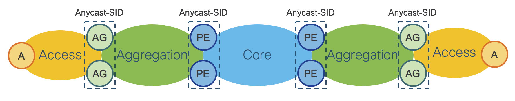
Figure 4: IGP Domains - ABRs Anycast-SID
Figure 5 shows the End-To-End Stack of SIDs for packets traveling from left to right through the network.
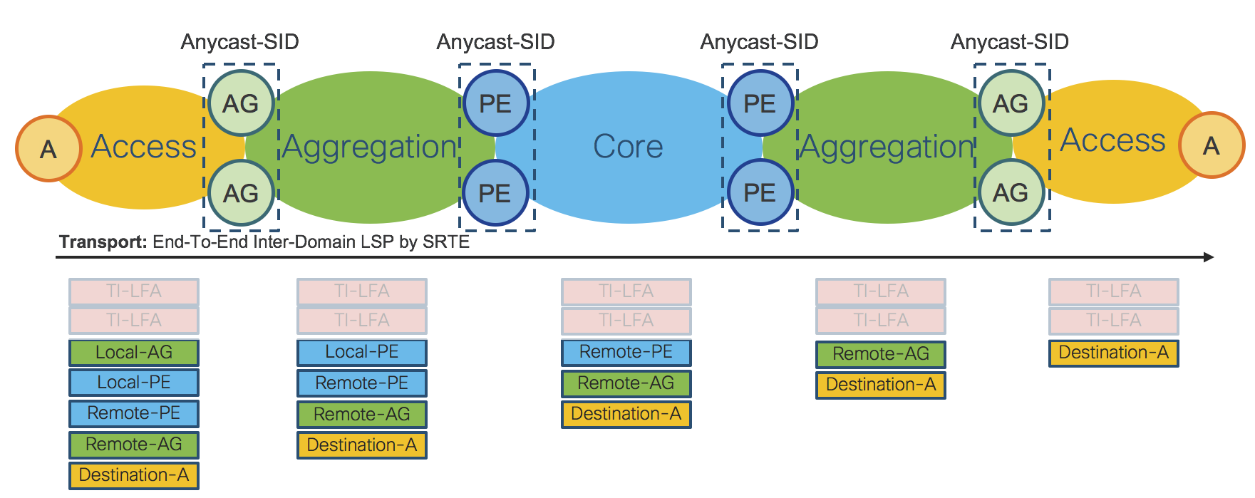
Figure 5: Inter-Domain LSP – SRTE Policy
The End-To-End Inter-Domain Label Switched Path (LSP) was computed via Segment Routing Traffic Engineering (SRTE) Policies.
On the Access router “A” the SRTE Policy imposes:
Local Aggregation Area Border Routers Anycast-SID: Local-AG Anycast-SID
Local Provider Edge Area Border Routers Anycast-SID: Local-PE Anycast SID
Remote Provider Edge Area Border Routers Anycast-SID: Remote-PE Anycast-SID
Remote Aggregation Area Border Routers Anycast-SID: Remote-AG Anycast-SID
Remote/Destination Access Router: Destination-A Prefix-SID: Destination-A Prefix-SID
The SRTE Policy is programmed on the Access device on-demand by an external Controller and does not require any state to be signaled throughout the rest of the network. The SRTE Policy provides, by simple SID stacking (SID-List), an elegant and robust way to program Inter-Domain LSPs without requiring additional protocols such as BGP-LU (RFC3107).
Please refer to Section: “Transport Programmability” for additional details.
Area Border Routers – Prefix-SID vs Anycast-SID
Section: “Inter-Domain Forwarding” showed the use of Anycast-SID at the ABRs for the provisioning of an Access to Access End-To-End LSP. When the LSP is set up between the Access Router and the AG/PE ABRs, there are two options:
ABRs are represented by Anycast-SID; or
Each ABR is represented by a unique Prefix-SID.
Choosing between Anycast-SID or Prefix-SID depends on the requested service. Please refer to Section: “Services - Design”.
Note that both options can be combined on the same network.
Inter-Domain Forwarding - Label Stack Optimization
Section: “Inter-Domain Forwarding” described how SRTE Policy uses SID stacking (SID-List) to define the Inter-Domain End-To-End LSP. The SID-List has to be optimized to be able to support different HW capabilities on different service termination platforms, while retaining all the benefits of a clear, simple and robust design.
Figure 6 shows the optimization in detail.
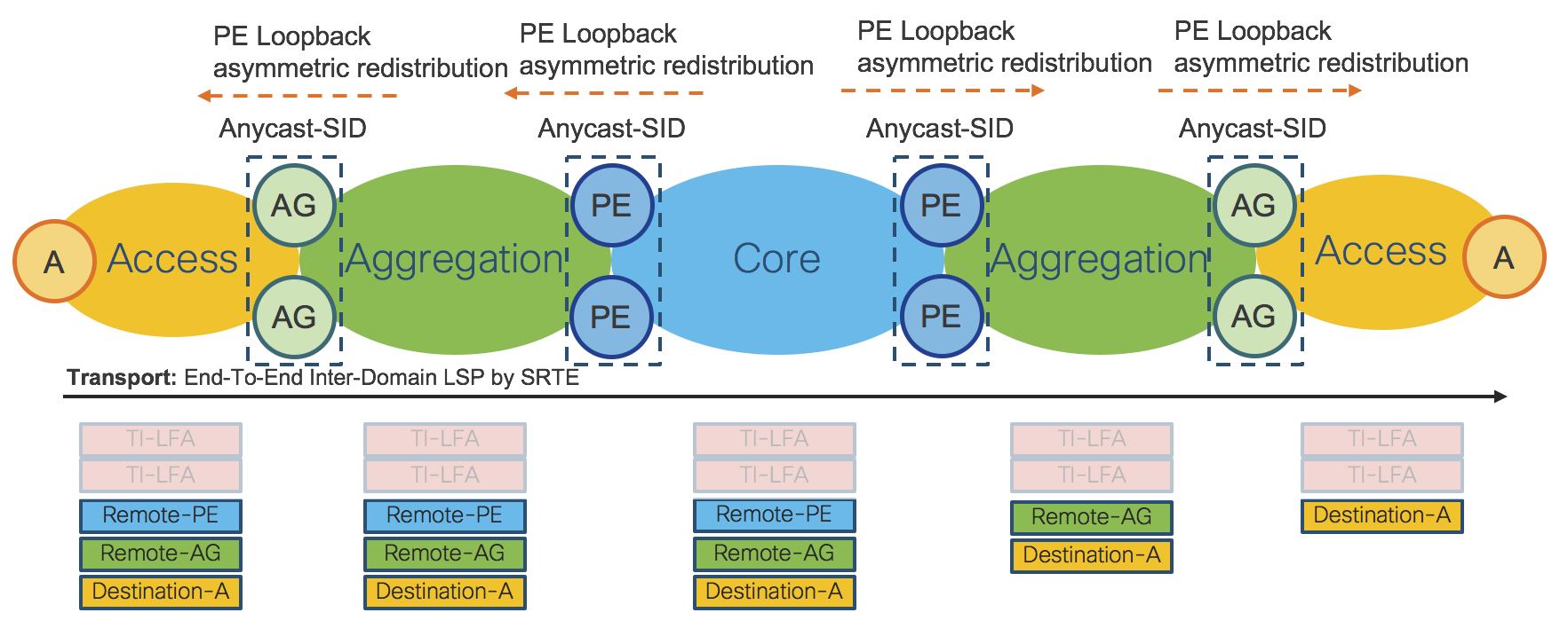
Figure 6: Label Stack Optimization
The Anycast-SIDs and the Anycast Loopback IP address of all PE ABRs in the network are redistributed into the Aggregation IGP Domain by the local PE ABRs. By doing this, all nodes in a Aggregation IGP Domain know, via IGP, the Anycast-SID of all PE ABRs in the network. Local AG ABRs then redistribute the Anycast-SIDs and Anycast Loopback IP address of all PE ABRs into the Access IGP Domain. By doing this, all nodes in a Access IGP Domain also know, via IGP, the Anycast-SID of all PE ABRs in the network.
It is very important to note that this redistribution is asymmetric, thus it won’t cause any L3 routing loop in the network.
Another important fact to consider is that there is only a limited amount of PEs in a Service Provider Network, therefore the redistribution does not affect scalability in the Access IGP Domain.
After Label Stack Optimization, the SRTE Policy on the Access router imposes:
Remote Provider Edge Area Border Routers Anycast-SID: Remote-PE Anycast-SID
Remote Aggregation Are Border Routers Anycast-SID: Remote-AG Anycast-SID
Remote/Destination Access Router: Destination-A Prefix-SID: Destination-A Prefix-SID
Because of the Label Stack Optimization, the total amount of SIDs required for the Inter-Domain LSP is reduced to 3 instead of the original 5.
The Label Stack Optimization mechanism is very similar when an ABR is represented by a Prefix-SID instead of an Anycast-SID. The Prefix-SID and the unicast Loopback IP address are redistributed into the Aggregation IGP Domain by Local PE ABRs. By doing this, all nodes in the Aggregation IGP Domain know, via IGP, the Prefix-SID of all PE ABRs in the network. Local AG ABRs then redistribute the learned Prefix-SIDs and unicast Loopback IP address of all PE ABRs to the Access IGP Domain. By doing this, all nodes in a Access IGP Domain know, via IGP, the Prefix-SID of all PE ABRs in the network.
Both Anycast-SID and Prefix-SID can be combined in the same network with or without Label Stack Optimization.
Inter-Domain Forwarding - High Availability and Fast Re-Route
AG/PE ABRs redundancy enables high availability for Inter-Domain Forwarding.
Figure 7: IGP Domains - ABRs Anycast-SID
When Anycast-SID is used to represent AG or PE ABRs, no other mechanism is needed for Fast Re-Route (FRR). Each IGP Domain provides FRR independently by TI-LFA as described in Section: “Intra-Domain Forwarding - Fast Re-Route”.
Figure 8 shows how FRR is achieved for a Inter-Domain LSP.
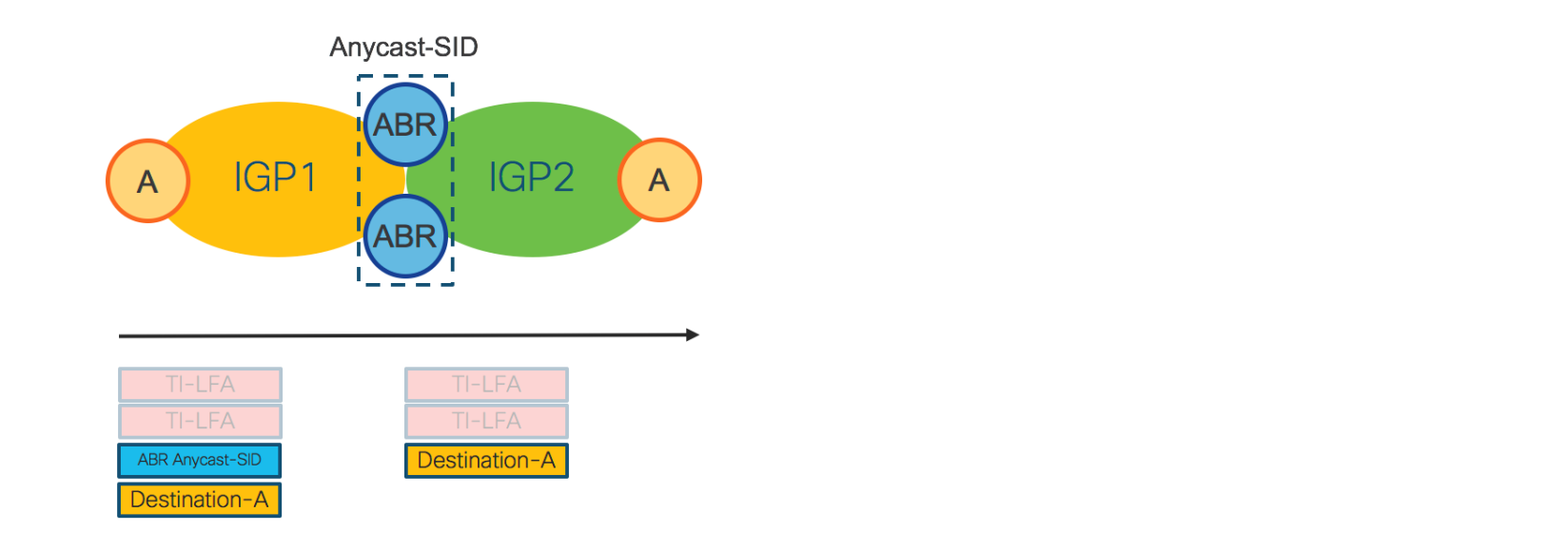
Figure 8: Inter-Domain - FRR
The access router on the left imposes the Anycast-SID of the ABRs and the Prefix-SID of the destination access router. For FRR, any router in IGP1, including the Access router, looks at the top label: “ABR Anycast-SID”. For this label, each device maintains a primary and backup path preprogrammed in the HW. In IGP2, the top label is “Destination-A”. For this label, each node in IGP2 has primary and backup paths preprogrammed in the HW. The backup paths are computed by TI-LFA.
As Inter-Domain forwarding is achieved via SRTE Policies, FRR is completely self-contained and does not require any additional protocol.
Note that when traditional BGP-LU is used for Inter-Domain forwarding, BGP-PIC is also required for FRR.
Inter-Domain LSPs provisioned by SRTE Policy are protected by FRR also in case of ABR failure (because of Anycast-SID). This is not possible with BGP-LU/BGP-PIC, since BGP-LU/BGP-PIC have to wait for the IGP to converge first.
Transport Programmability
Figure 9 and Figure 10 show the design of Router-Reflectors (RR), Segment Routing Path Computation Element (SR-PCE) and WAN Automation Engines (WAE). High-Availability is achieved by device redundancy in the Aggregation and Core networks.
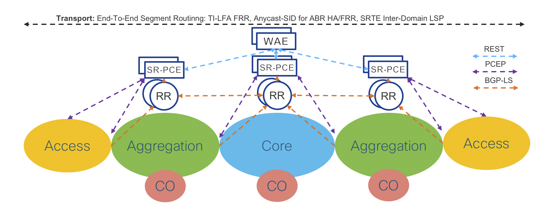
Figure 9: Transport Programmability – PCEP
RRs collect network topology from ABRs through BGP Link State (BGP-LS). Each ABR has a BGP-LS session with the two Domain RRs.
Aggregation Domain RRs collect network topology information from the Access and the Aggregation IGP Domain (Aggregation ABRs are part of the Access and the Aggregation IGP Domain). Core Domain RRs collect network topology information from the Core IGP Domain.
Aggregation Domain RRs have BGP-LS sessions with Core RRs.
Through the Core RRs, the Aggregation Domains RRs advertise local Aggregation and Access IGP topologies and receive the network topologies of the remote Access and Aggregation IGP Domains as well as the network topology of the Core IGP Domain. Hence, each RR maintains the overall network topology in BGP-LS.
Redundant Domain SR-PCEs have BGP-LS sessions with the local Domain RRs through which they receive the overall network topology. Refer to Section: “Segment Routing Path Computation Element (SR-PCE)” for more details about SR-PCE.
SR-PCE is then capable of computing the Inter-Domain LSP path on-demand and to instantiate it. The computed path (SID-List) is then advertised via the Path Computation Element Protocol (PCEP), as shown in Figure 9, or BGP-SRTE, as shown in Figure 10, to the Service End Points. In the case of PCEP, SR-PCEs and Service End Points communicate directly, while for BGP-SRTE, they communicate via RRs. Phase 1 uses PCEP only.
The Service End Points program the SID-List via SRTE Policy.
Service End Points can be co-located with the Access Routers for Flat Services or at the ABRs for Hierarchical Services. The SRTE Policy Data Plane in the case of Service End Point co-located with the Access router was described in Figure 5.
The WAN Automation Engine (WAE) provides bandwidth optimization.
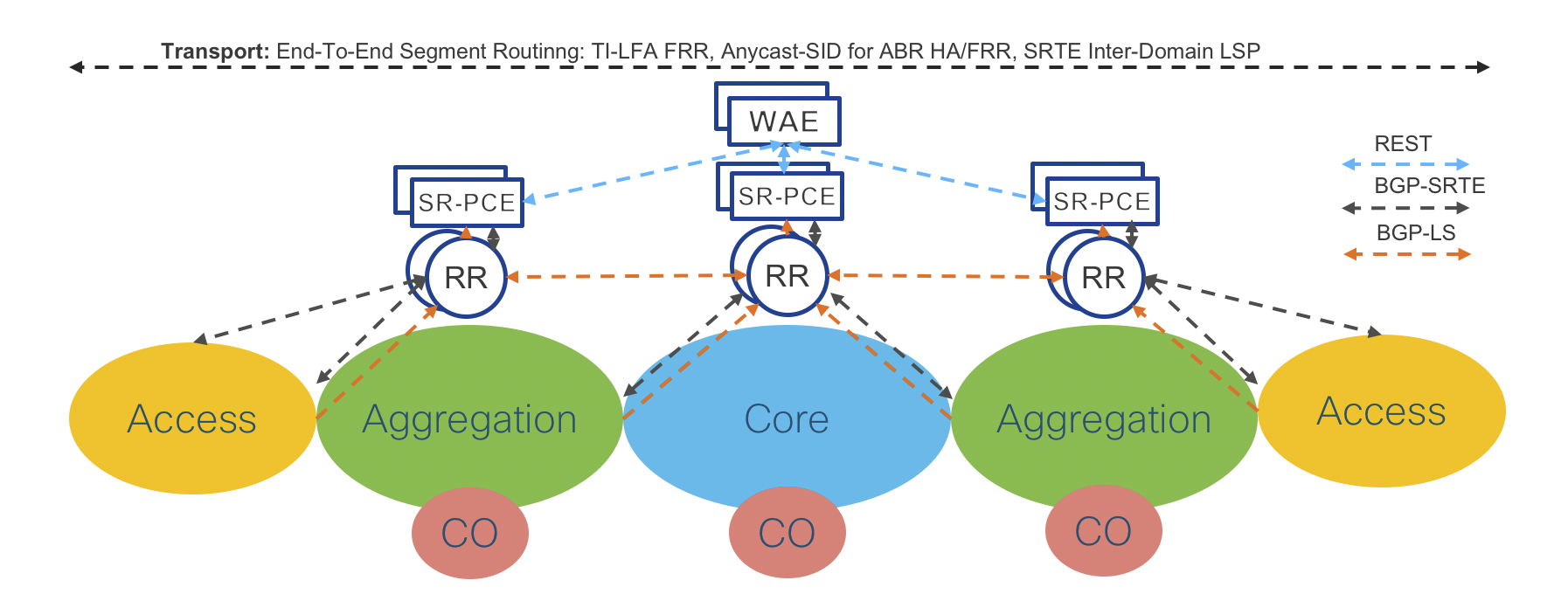
Figure 10: Transport Programmability – BGP-SRTE
The proposed design is very scalable and can be easily extended to support even higher numbers of BGP-SRTE/PCEP sessions by adding additional RRs and SR-PCEs into the Access Domain.
Figure 11 shows the Compass Metro Fabric physical topology with examples of product placement.
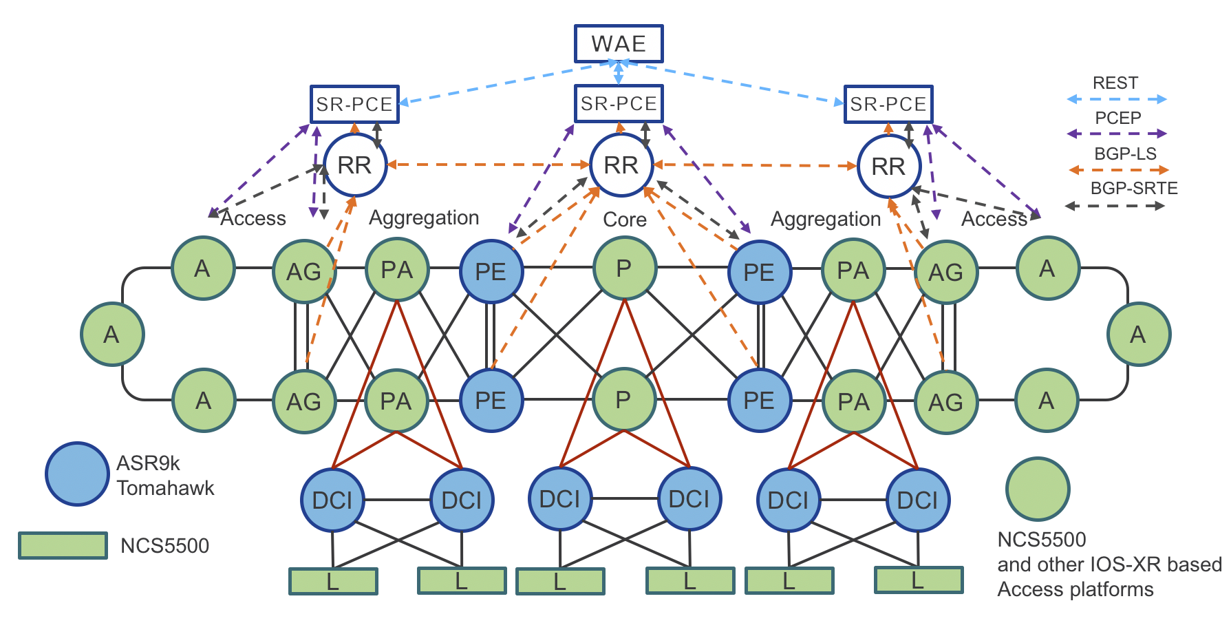
Figure 11: Compass Metro Fabric – Physical Topology with transport programmability
Note that the design of the Central Office is not covered by this document.
###Traffic Engineering (Tactical Steering) – SRTE Policy
Operators want to fully monetize their network infrastructure by offering differentiated services. Traffic engineering is used to provide different paths (optimized based on diverse constraints, such as low-latency or disjoined paths) for different applications. The traditional RSVP-TE mechanism requires signaling along the path for tunnel setup or tear down, and all nodes in the path need to maintain states. This approach doesn’t work well for cloud applications, which have hyper scale and elasticity requirements.
Segment Routing provides a simple and scalable way of defining an end-to-end application-aware traffic engineering path computed once again through SRTE Policy.
In the Compass Metro Fabric design, the Service End Point uses PCEP or BGP-SRTE (Phase 1 uses PCEP only) along with Segment Routing On-Demand Next-hop (SR-ODN) capability, to request from the controller a path that satisfies specific constraints (such as low latency). This is done by associating an SLA tag/attribute to the path request. Upon receiving the request, the SR-PCE controller calculates the path based on the requested SLA, and uses PCEP or BGP-SRTE to dynamically program the ingress node with a specific SRTE Policy.
The Compass Metro Fabric design also uses MPLS Performance Management to monitor link delay/jitter/drop (RFC6374).
Transport Controller Path Computation Engine (PCE)
Segment Routing Path Computation Element (SR-PCE)
Segment Routing Path Computation Element, or SR-PCE, is a Cisco Path Computation Engine (PCE) and it is implemented as a feature included as part of Cisco IOS-XR operating system. The function is typically deployed on a Cisco IOS-XR cloud appliance XRv9000, as it involves control plane operations only. The SR-PCE gains network topology awareness from BGP-LS advertisements received from the underlying network. Such knowledge is leveraged by the embedded multi-domain computation engine to provide optimal path to Path Computation Element Clients (PCCs) using the Path Computation Element Protocol (PCEP) or BGP-SRTE.
The PCC is the device where the service originates and therefore it requires end-to-end connectivity over the segment routing enabled multi-domain network.
The SR-PCE provides a path based on constraints such as:
Shortest path (IGP metrics).
Traffic-Engineering metrics.
Disjoint path.
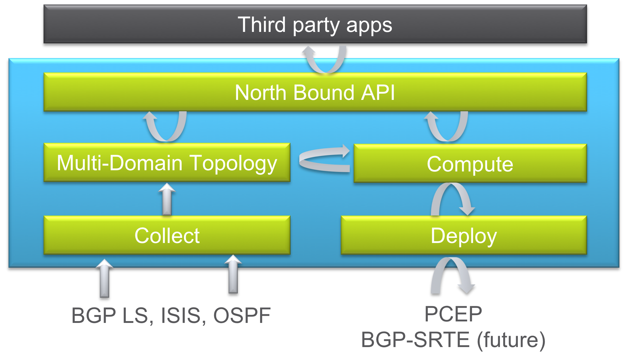
Figure 12: XR Transport Controller – Components
WAN Automation Engine (WAE)
WAE Automation combines the smart data collection, modeling, and predictive analytics of Cisco WAE Planning with an extensible, API-driven configuration platform. The use of open APIs and standardized protocols provides a means for intelligent interaction between applications and the network. Applications have visibility into the global network and can make requests for specific service levels. Section: “PCE Controller Summary - SR-PCE & WAE” compares SR-PCE and WAE.
PCE Controller Summary – SR-PCE & WAE
Segment Routing Path Computation Element (SR-PCE):
Runs as a features in a IOS-XR node
Collects topology from BGP, ISIS, OSPF and BGP Link State
Deploys tunnel: PCEP SR/RSVP, BGP SR-TE
Computes Shortest, Disjoint, Low Latency, and Avoidance paths
North Bound interface with applications via REST API
WAN Automation Engine (WAE):
Runs as a SR-PCE application
Collects topology: via SR-PCE
Collects BW utilization: Flexible NetFlow (FNF), Streaming Telemetry, SNMP
Deploys tunnel via SR-PCE (preferred: stateful) or NSO (optional: stateless)
Computes: Bandwidth Optimization, On demand BW.
Path Computation Engine – Workflow
There are three models available to program transport LSPs:
Delegated Computation to SR-PCE
WAE Instantiated LSP
Delegated Computation to WAE
All models assume SR-PCE has acquired full network topology through BGP-LS.
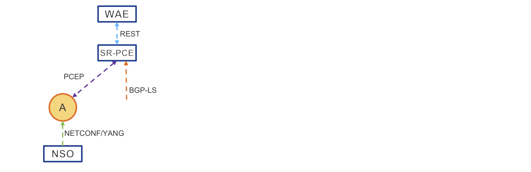
Figure 13: PCE Path Computation
Delegated Computation to SR-PCE
NSO provisions the service. Alternatively, the service can be provisioned via CLI
Access Router requests a path
SR-PCE computes the path
SR-PCE provides the path to Access Router
Access Router acknowledges
(Optional) When WAE is deployed for LSP visibility, SR-PCE updates WAE with the newer LSP
WAE Instantiated LSP
WAE computes the path
WAE sends computed path to SR-PCE
SR-PCE provides the path to Access Router
Access Router confirms
SR-PCE updates WAE with newer LSP
Delegated Computation to WAE
NSO provisions the service – Service can also be provisioned via CLI
Access Router requests a path
SR-PCE delegates computation to WAE
WAE computes the path
WAE sends computed path to SR-PCE
SR-PCE provides the path to Access Router
Access Router confirms
SR-PCE updates WAE with newer LSP
Transport – Segment Routing IPv6 Data Plane (SRv6)
The Compass Metro Fabric design will use Segment Routing IPv6 Data Plane (SRv6) in later phases.
SRv6 brings another level of simplification with IPv6 data plane and with network programming concept.
Network programming concept is the capability to encode a network program in the header of the packet. The program is expressed as a list of segments included in the SRv6 extension header, also called SRH. Each segment is a 128-bit entity where the first bits identify a router in the network, we call them the locator part of the segment, and the remaining bits identify a function to be executed at that router.
The SRv6 network programming IETF draft (draft-filsfils-spring-srv6-network-programming) provides the pseudo-code for various functions that allow the implementation of network services such as TILFA FRR, TE for latency or disjointness, VPN, NFV and many other applications.
The following diagram: “SRv6 Network Topology” shows customer’s IPv6 traffic with destination IPv6 address 6001::1 (same can be done for IPv4 traffic) encapsulated in SRv6 on router 1, then forwarded via SRv6 core to router 4 via router 2 or via router 3. Router 4 decapsulates SRv6 and performs IPv6 destination address lookup in customer VRF. In our use case, VRF 100.
All the links in the topology except the link between routers 3 and 4 are equal. the Link between 3 and 4 is high cost, but has low latency
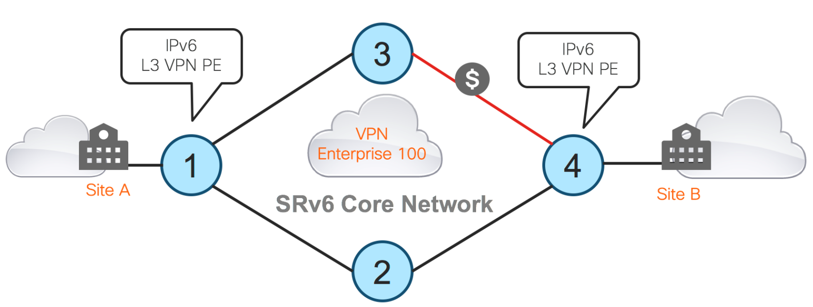
Figure 14: SRv6 Network Topology
Best-Effort Path
The following diagram: “SRv6 Best-Effort Path” shows best-effort path. Router 1 encapsulates the received IPv6 packets from the customer site of Entreprise100 in an outer IPv6 header. Router 1 sets the destination address of the outer header to the segment of Router 4 which implements the egress PE function related to the VPN of Entreprise100 at Router 4. In this example, this segment is 2001::4:E100. The bits “2001::4” locate the router where the function will be executed.
In this example, we assume that Router 4 would advertise 2001::4/112 in the IGP (no new IETF extension is required for this). The bits “E100” identify a specific function to be executed at the router identified by the locator bits, in our example, Router 4.
We assume here that Router 4 has instantiated the local function “E100” for the behavior “decap the packet, lookup the inner destination address in the VRF of Entreprise 100 and forward accordingly”.
We also assume that Router 4 has signaled the availability of that function to Router 1 either via BGP or via an SDN controller.
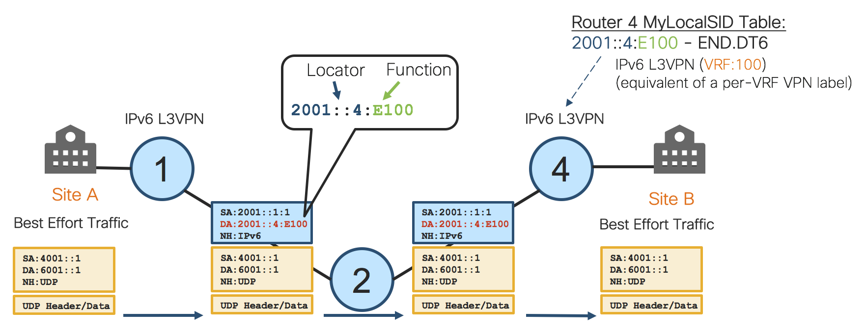
Figure 15: SRv6 Best-Effort Path
Router 1 receives packets from Entreprise100, then encapsulates these packets in an outer header with DA leading to Router 4 where the function “decap and lookup in VRF 100” is executed.
By the process above, we have eliminated any encapsulation protocol such as LISP, VXLAN, L2TPv3, GRE etc. This is an important simplification.
We have not used an SRH in this case because the network program can be encoded with one single segment and hence we just need the outer IPv6 header.
The example above shows IPv6 VPN over IPv6. The same is applicable for IPv4 overlay (IPv4 VPN) and L2VPN construct. More details can be found in draft-filsfils-spring-srv6-network-programming.
Low-Latency Path
The following diagram: “SRv6 Low-Latency Path” shows low-latency path. Router 1 encapsulates the customer traffic in an outer IPv6 header with an SRH. In this example, the network program needs two SID’s. The first SID is placed in the DA and implements the low-latency underlay service. The second SID is programmed in the SRH and implements the overlay service.
The first SID is 2001::3:C34.
2001::3 is the locator part and leads the packet to Router 3. Once Router 3 gets this packet, it executes the function C34. The function C34 means “update the DA with the next-segment and cross-connect the resulting packet to the neighboring Router 4.”
We assume here that Router 3 has instantiated the local function “C34” for the behavior “update DA, cross-connect to neighbor 4”.
We also assume that Router 4 has signaled the availability of that function to Router 1 via the IGP.
With one single SID, the ingress PE encodes in the packet header the underlay SLA service for low-latency. The packets will use the north path despite that it is not the preferred one from an IGP viewpoint. This is achieved by using the explicit routing capability of SR.
State is created in the fabric to create this underlay SLA.
The second SID implements the overlay service: this is 2001::4:E100 like we saw previously.
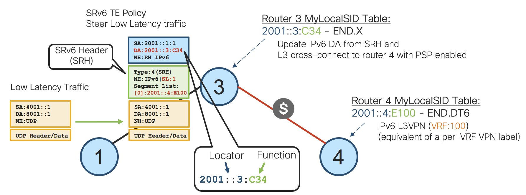
Figure 16: SRv6 Low-Latency Path
The following diagram: ”SRv6 Cross-Connect Function” shows the cross-connect function 2001::3:C34 instantiated by Router 3 as this explicit routing function provides a nice and easy way to enforce requested SRTE Policy without any stateful information as the network program is in the packet header.
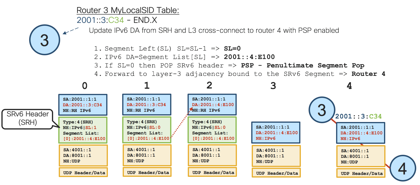
Figure 17: SRv6 Cross-Connect Function
“Cross-connect” means the function 2001::3:C34 is bound specifically to the red link between Routers 3 and 4, but before Router 3 can cross-connect the packets, the IPv6 header needs to be updated.
SRH can carry multiple segments stored in the segment list, so there is also index represented by segment left value in SRH, which points to the right segment in the segment list. In our example, we have just one segment in SRH which is the segment of Router 4.
First, Router 3 decreases segment left value by one.
In the next step, Router 3 will use segment left value as index in the segment list to read the next segment. Router 3 sets the new destination address of outer header to this segment which is the segment of Router 4.
This is completely the same segment of Router 4 like in the first use case which implements the egress PE function related to VPN of Enterprise 100 at Router 4.
In our example, SRH doesn’t carry other segments, therefor Router 3 can pop this SRH header. We call this operation Penultimate Segment Pop.
Finally, Router 3 cross-connects the packet to Router 4 via the red link.
Router 4 decapsulates the packet, lookups the inner destination address in the VRF Enterprise 100 and forwards accordingly.
The following diagram: ”SRv6 Low-Latency Detail” shows end-to-end low-latency traffic data-path described in the previous paragraph.
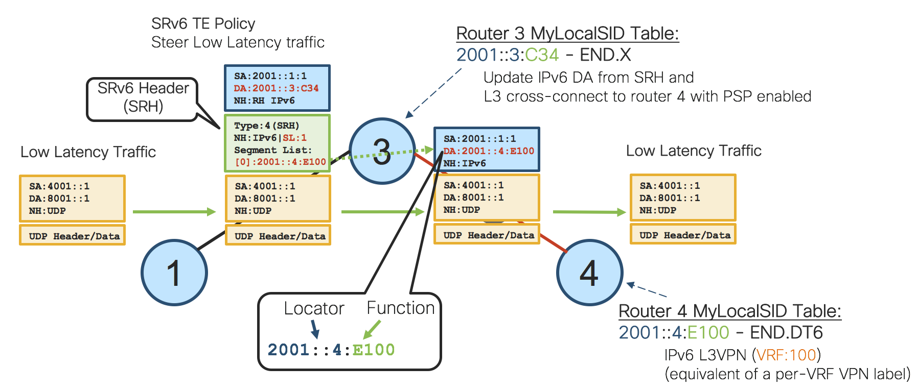
Figure 18: SRv6 Low-Latency Detail
SRv6 – Inter-Domain Forwarding
Next network diagram: “SRv6 Inter-Domain Forwarding” shows how SRv6 benefits can be used in Service Provider network for Inter-Domain forwarding. End-To-End forwarding reachability can be easily provided by summary or default route in the Access IGP Domain pointing to AG ABRs. Similarly, the Aggregation IGP Domain has summary or default route pointing to PE ABRs. The Core IGP domain also has summary routes of the Aggregation/Access IGP Domains pointing to particular PE ABRs.
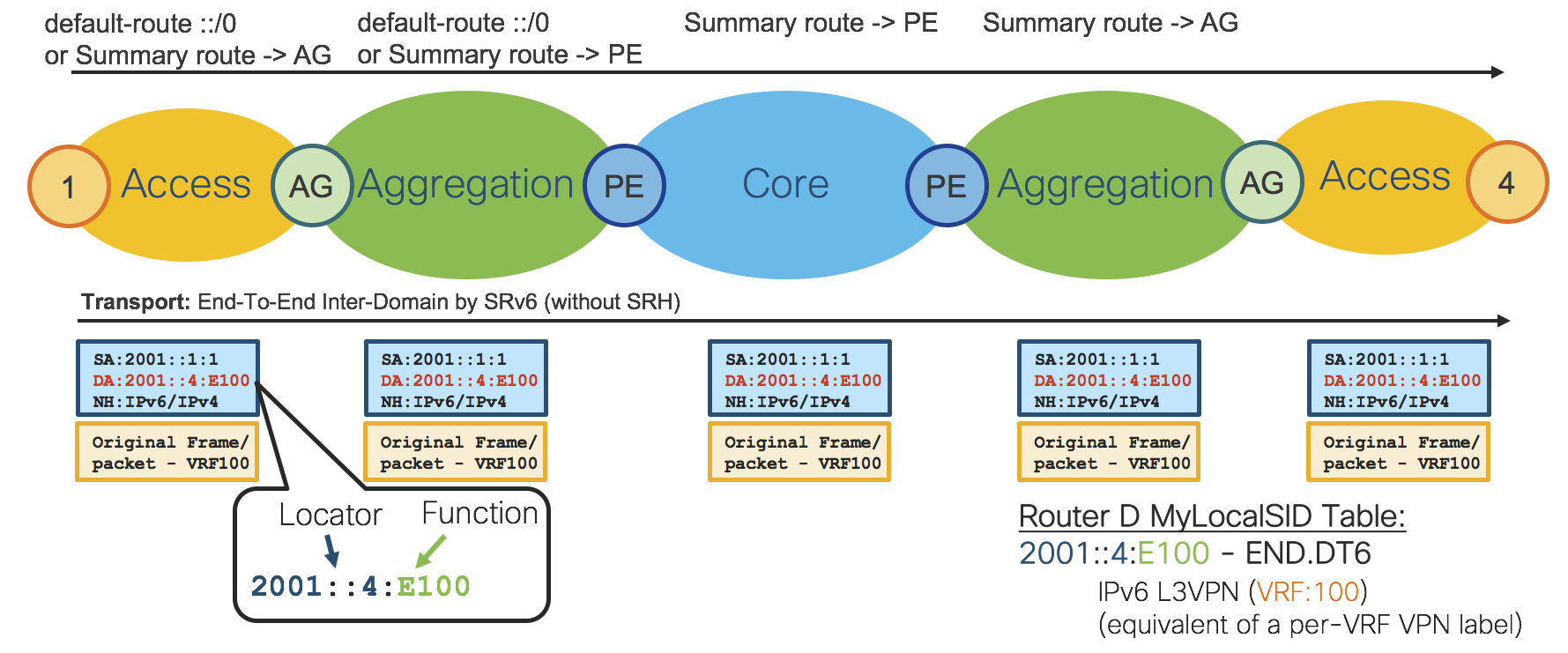
Figure 19: SRv6 Inter-Domain Forwarding
Next network diagram: “SRv6 Inter-Domain Forwarding with SRH” shows how SRH can also be used to get Inter-Domain with Traffic Engineering (Low-Latency Path).
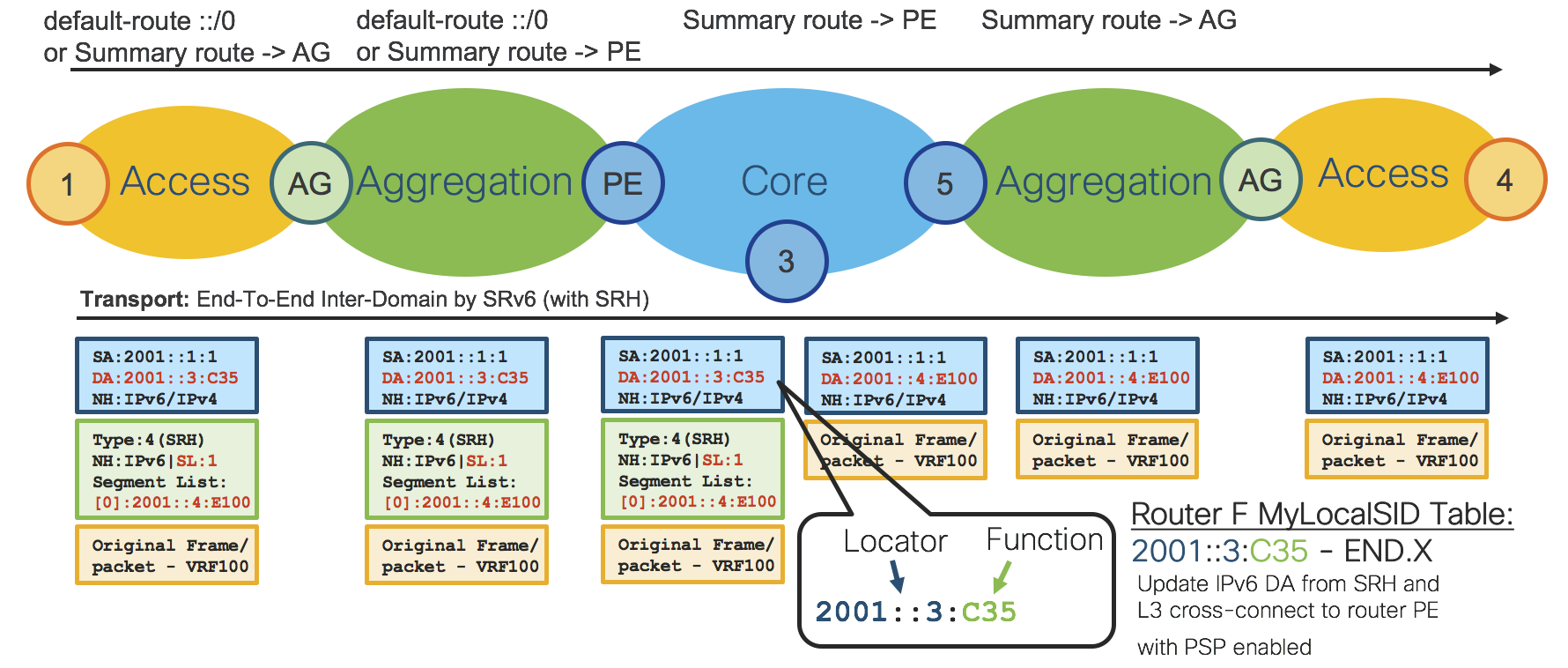
Figure 20: SRv6 Inter-Domain Forwarding with SRH
Note that there is SDN controller to fulfill SLAs required by provisioned services and SRTE Policy is programmed to network based on the SLAs.
Segment Routing basic elements are the same for MPLS as well as for IPv6(SRv6) data plane.
SRv6 Conclusion
SRv6 brings the following benefits to an SP network
Simplicity
Removal of any encapsulation protocol such as GRE, L2TPv3, LISP.
Stateless and Scalable
The network program is in the packet header not as a state in the fabric
Services – Design
Overview
The Compass Metro Fabric Design aims to enable simplification across all layers of a Service Provider network. Thus, the Compass Metro Fabric services layer focuses on a converged Control Plane based on BGP.
BGP based Services include EVPNs and Traditional L3VPNs (VPNv4/VPNv6).
EVPN is a technology initially designed for Ethernet multipoint services to provide advanced multi-homing capabilities. By using BGP for distributing MAC address reachability information over the MPLS network, EVPN brought the same operational and scale characteristics of IP based VPNs to L2VPNs. Today, beyond DCI and E-LAN applications, the EVPN solution family provides a common foundation for all Ethernet service types; including E-LINE, E-TREE, as well as data center routing and bridging scenarios. EVPN also provides options to combine L2 and L3 services into the same instance.
To simplify service deployment, provisioning of all services is fully automated using Cisco Network Services Orchestrator (NSO) using (YANG) models and NETCONF. Refer to Section: “Network Services Orchestrator (NSO)”.
There are two types of services: End-To-End and Hierarchical. The next two sections describe these two types of services in more detail.
Ethernet VPN (EVPN)
EVPNs solve two long standing limitations for Ethernet Services in Service Provider Networks:
Multi-Homed & All-Active Ethernet Access
Service Provider Network - Integration with Central Office or with Data Center
Multi-Homed & All-Active Ethernet Access
Figure 21 demonstrates the greatest limitation of traditional L2 Multipoint solutions like VPLS.
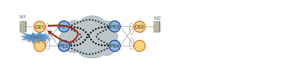
Figure 21: EVPN All-Active Access
When VPLS runs in the core, loop avoidance requires that PE1/PE2 and PE3/PE4 only provide Single-Active redundancy toward their respective CEs. Traditionally, techniques such mLACP or Legacy L2 protocols like MST, REP, G.8032, etc. were used to provide Single-Active access redundancy.
The same situation occurs with Hierarchical-VPLS (H-VPLS), where the access node is responsible for providing Single-Active H-VPLS access by active and backup spoke pseudowire (PW).
All-Active access redundancy models are not deployable as VPLS technology lacks the capability of preventing L2 loops that derive from the forwarding mechanisms employed in the Core for certain categories of traffic. Broadcast, Unknown-Unicast and Multicast (BUM) traffic sourced from the CE is flooded throughout the VPLS Core and is received by all PEs, which in turn flood it to all attached CEs. In our example PE1 would flood BUM traffic from CE1 to the Core, and PE2 would sends it back toward CE1 upon receiving it.
EVPN uses BGP-based Control Plane techniques to address this issue and enables Active-Active access redundancy models for either Ethernet or H-EVPN access.
Figure 22 shows another issue related to BUM traffic addressed by EVPN.
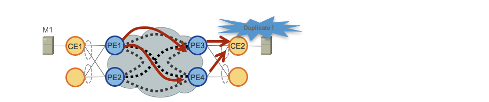
Figure 22: EVPN BUM Duplication
In the previous example, we described how BUM is flooded by PEs over the VPLS Core causing local L2 loops for traffic returning from the core.
Another issue is related to BUM flooding over VPLS Core on remote PEs. In our example either PE3 or PE4 receive and send the BUM traffic to their attached CEs, causing CE2 to receive duplicated BUM traffic.
EVPN also addresses this second issue, since the BGP Control Plane allows just one PE to send BUM traffic to an All-Active EVPN access.
Figure 23 describes the last important EVPN enhancement.
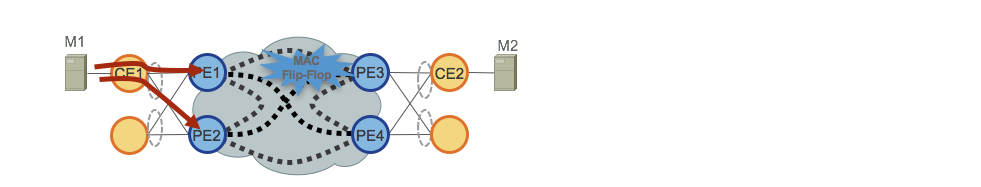
Figure 23: EVPN MAC Flip-Flopping
In the case of All-Active access, traffic is load-balanced (per-flow) over the access PEs (CE uses LACP to bundle multiple physical ethernet ports and uses hash algorithm to achieve per flow load-balancing). Remote PEs, PE3 and PE4, receive the same flow from different neighbors. With a VPLS core, PE3 and PE4 would rewrite the MAC address table continuously, each time the same mac address is seen from a different neighbor.
EVPN solves this by mean of “Aliasing”, which is also signaled via the BGP Control Plane.
Service Provider Network - Integration with Central Office or with Data Center
Another very important EVPN benefit is the simple integration with Central Office (CO) or with Data Center (DC). Note that Metro Central Office design is not covered by this document.
The adoption of EVPNs provides huge benefits on how L2 Multipoint technologies can be deployed in CO/DC. One such benefit is the converged Control Plane (BGP) and converged data plane (SR MPLS/SRv6) over SP WAN and CO/DC network.
Moreover, EVPNs can replace existing proprietary Ethernet Multi-Homed/All-Active solutions with a standard BGP-based Control Plane.
End-To-End (Flat) – Services
The End-To-End Services use cases are summarized in the table in Figure 24 and shown in the network diagram in Figure 25.
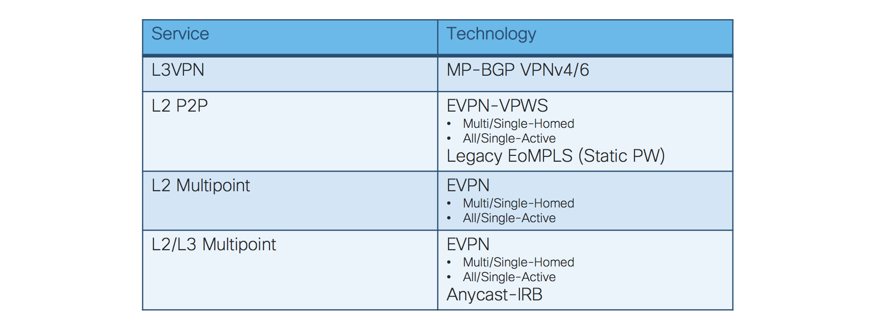
Figure 24: End-To-End – Services table
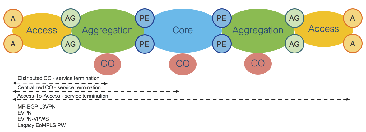
Figure 25: End-To-End – Services
All services use cases are based on BGP Control Plane.
Refer also to Section: “Transport and Services Integration”.
Hierarchical – Services
Hierarchical Services Use Cases are summarized in the table of Figure 26 and shown in the network diagram of Figure 27.
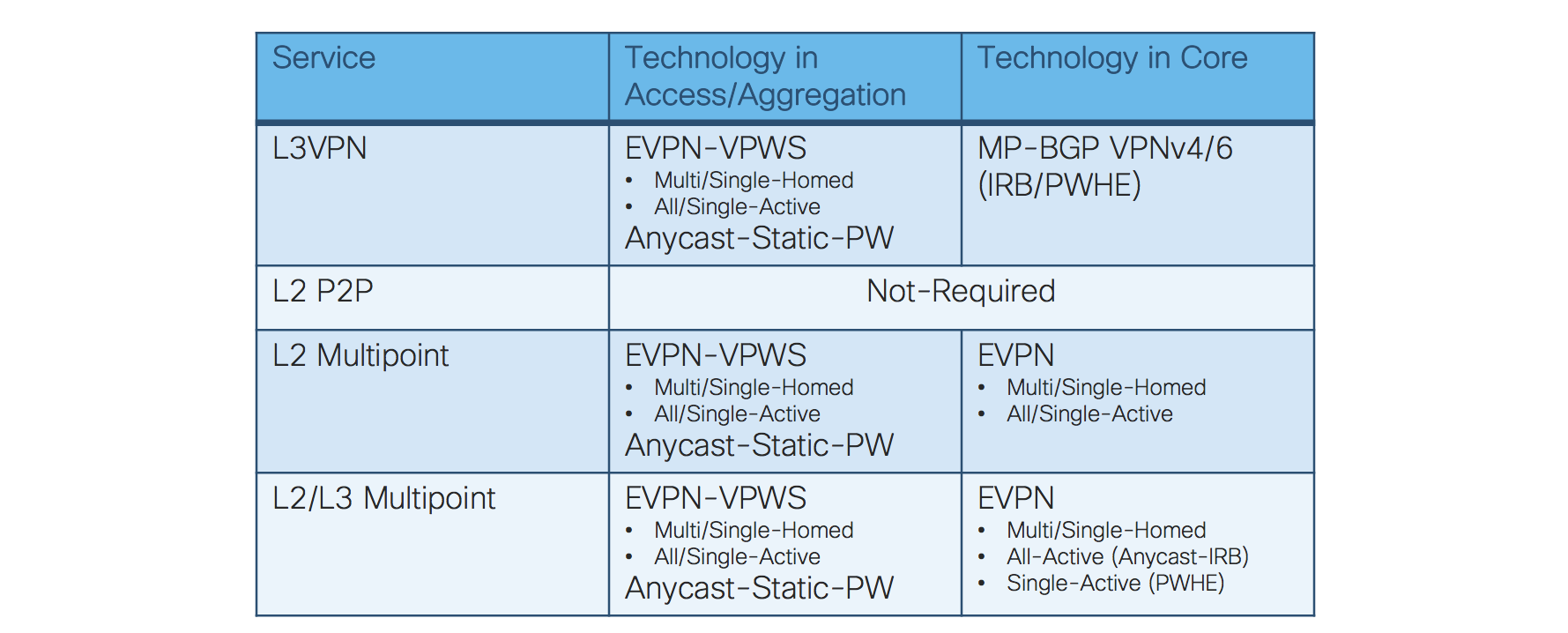
Figure 26: Hierarchical – Services table
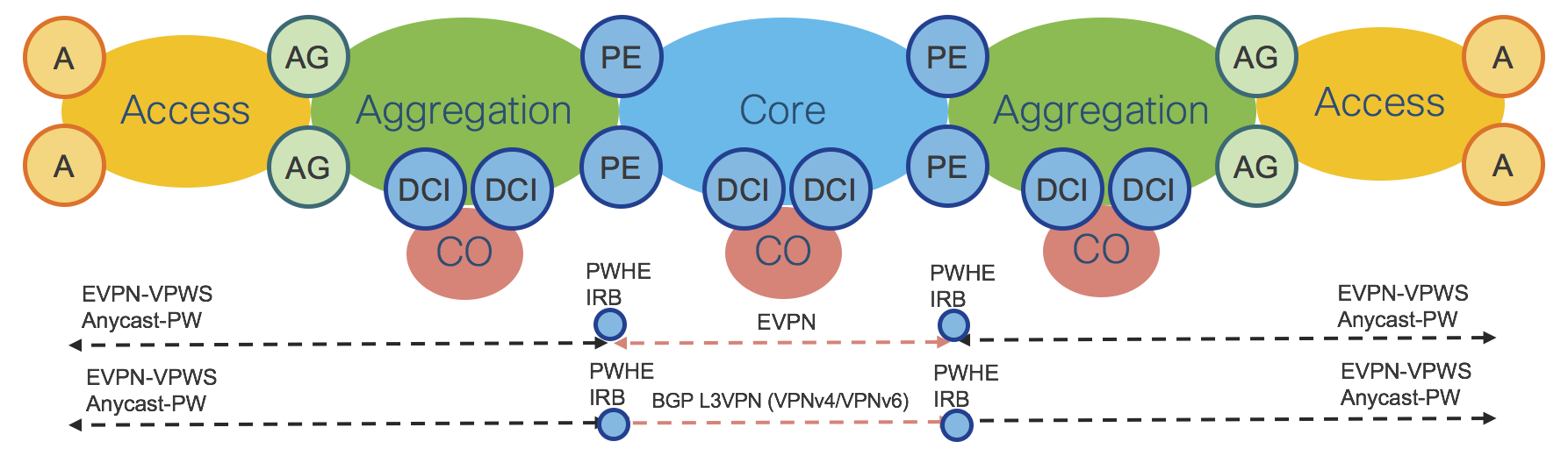
Figure 27: Hierarchical - Services
Hierarchical services designs are critical for Service Providers looking for limiting requirements on the access platforms and deploying more centralized provisioning models that leverage very rich features sets on a limited number of touch points.
Hierarchical Services can also be required by Service Providers who want to integrate their SP-WAN with the Central Office/Data Center network using well-established designs based on Data Central Interconnect (DCI).
Figure 27 shows hierarchical services deployed on PE routers, but the same design applies when services are deployed on AG or DCI routers.
The Compass Metro Design offers scalable hierarchical services with simplified provisioning. The three most important use cases are described in the following sections:
Hierarchical L2 Multipoint Multi-Homed/All-Active
Hierarchical L2/L3 Multi/Single-Home, All/Single-Active Service (H-EVPN) and Anycast-IRB
Hierarchical L2/L3 Multipoint Multi-Homed/Single-Active (H-EVPN) and PWHE
Hierarchical L2 Multipoint Multi-Homed/All-Active
Figure 28 shows a very elegant way to take advantage of the benefits of Segment-Routing Anycast-SID and EVPN. This use case provides Hierarchical L2 Multipoint Multi-Homed/All-Active (Single-Homed Ethernet access) service with traditional access router integration.
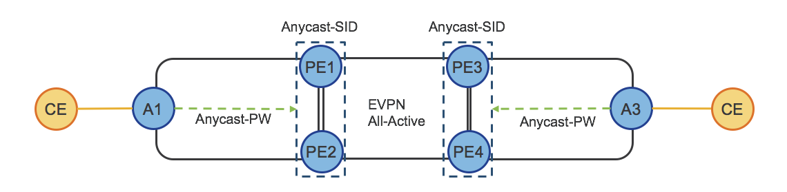
Figure 28: Hierarchical – Services (Anycast-PW)
Access Router A1 establishes a Single-Active static pseudowire (Anycast-Static-PW) to the Anycast IP address of PE1/PE2. PEs anycast IP address is represented by Anycast-SID.
Access Router A1 doesn’t need to establish active/backup PWs as in a traditional H-VPLS design and doesn’t need any enhancement on top of the established spoke pseudowire design.
PE1 and PE2 use BGP EVPN Control Plane to provide Multi-Homed/All-Active access, protecting from L2 loop, and providing efficient per-flow load-balancing (with aliasing) toward the remote PEs (PE3/PE4).
A3, PE3 and PE4 do the same, respectively.
Hierarchical L2/L3 Multi/Single-Home, All/Single-Active Service (H-EVPN) and Anycast-IRB
Figure 29 shows how EVPNs can completely replace the traditional H-VPLS solution. This use case provides the greatest flexibility as Hierarchical L2 Multi/Single-Home, All/Single-Active modes are available at each layer of the service hierarchy.
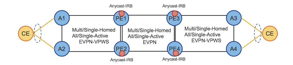
Figure 29: Hierarchical – Services (H-EVPN)
Optionally, Anycast-IRB can be used to enable Hierarchical L2/L3 Multi/Single-Home, All/Single-Active service and to provide optimal L3 routing.
Hierarchical L2/L3 Multipoint Multi-Homed/Single-Active (H-EVPN) and PWHE
Figure 30 shows how the previous H-EVPN can be extended by taking advantage of Pseudowire Headend (PWHE). PWHE with the combination of Multi-Homed, Single-Active EVPN provides an Hierarchical L2/L3 Multi-Homed/Single-Active (H-EVPN) solution that supports QoS.
It completely replaces traditional H-VPLS based solutions. This use case provides Hierarchical L2 Multi/Single-Home, All/Single-Active service.
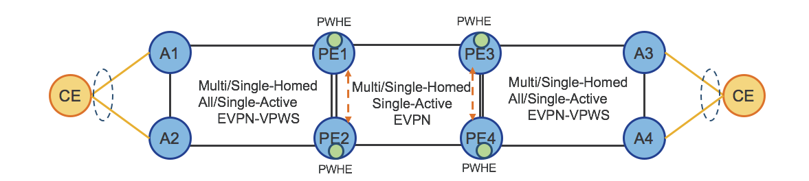
Figure 30: Hierarchical – Services (H-EVPN and PWHE)
Refer also to the section: “Transport and Services Integration”.
Services – Router-Reflector (S-RR)
Figure 31 shows the design of Services Router-Reflectors (S-RRs).
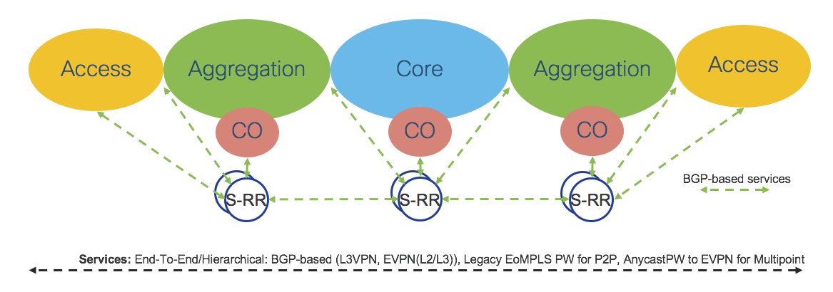
Figure 31: Services – Router-Reflectors
The Compass Metro Fabric Design focuses mainly on BGP-based services, therefore it is important to provide a robust and scalable Services Route-Reflector (S-RR) design.
For Redundancy reasons, there are at least 2 S-RRs in any given IGP Domain, although Access and Aggregation are supported by the same pair of S-RRs.
Each node participating in BGP-based service termination has two BGP sessions with Domain Specific S-RRs and supports multiple address-Families: VPNv4, VPNv6, EVPN.
Core Domain S-RRs cover the core Domain. Aggregation Domain S-RRs cover Access and Aggregation Domains. Aggregation Domain S-RRs and Core S-RRs have BGP sessions among each other.
The described solution is very scalable and can be easily extended to scale to higher numbers of BGP sessions by adding another pair of S-RRs in the Access Domain.
Network Services Orchestrator (NSO)
The NSO is a management and orchestration (MANO) solution for network services and Network Functions Virtualization (NFV). The NSO includes capabilities for describing, deploying, configuring, and managing network services and VNFs, as well as configuring the multi-vendor physical underlay network elements with the help of standard open APIs such as NETCONF/YANG or a vendor-specific CLI using Network Element Drivers (NED).
In the Compass Metro Fabric design, the NSO is used for Services Management, Service Provisioning, and Service Orchestration.
The NSO provides several options for service designing as shown in Figure 32
Service model with service template
Service model with mapping logic
Service model with mapping logic and service templates
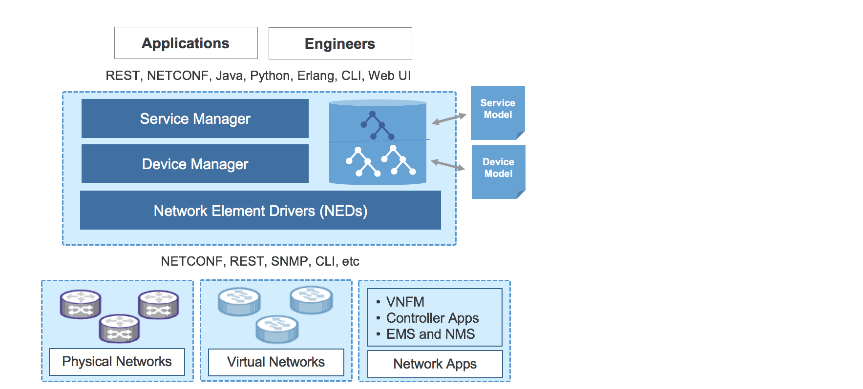
Figure 32: NSO – Components
A service model is a way of defining a service in a template format. Once the service is defined, the service model accepts user inputs for the actual provisioning of the service. For example, a E-Line service requires two endpoints and a unique virtual circuit ID to enable the service. The end devices, attachment circuit UNI interfaces, and a circuit ID are required parameters that should be provided by the user to bring up the E-Line service. The service model uses the YANG modeling language (RFC 6020) inside NSO to define a service.
Once the service characteristics are defined based on the requirements, the next step is to build the mapping logic in NSO to extract the user inputs. The mapping logic can be implemented using Python or Java. The purpose of the mapping logic is to transform the service models to device models. It includes mechanisms of how service related operations are reflected on the actual devices. This involves mapping a service operation to available operations on the devices.
Finally, service templates need to be created in XML for each device type. In NSO, the service templates are required to translate the service logic into final device configuration through CLI NED. The NSO can also directly use the device YANG models using NETCONF for device configuration. These service templates enable NSO to operate in a multi-vendor environment.
Transport and Services Integration
Section: “Transport - Design” described how Segment Routing provides flexible End-To-End and Any-To-Any Highly-Available transport together with Fast Re-Route. A converged BGP Control Plane provides a scalable and flexible solution also at the services layer.
Figure 33 shows a consolidated view of the Compass Metro Fabric network from a Control-Plane standpoint. Note that while network operators could use both PCEP and BGR-SRTE at the same time, it is not typical.
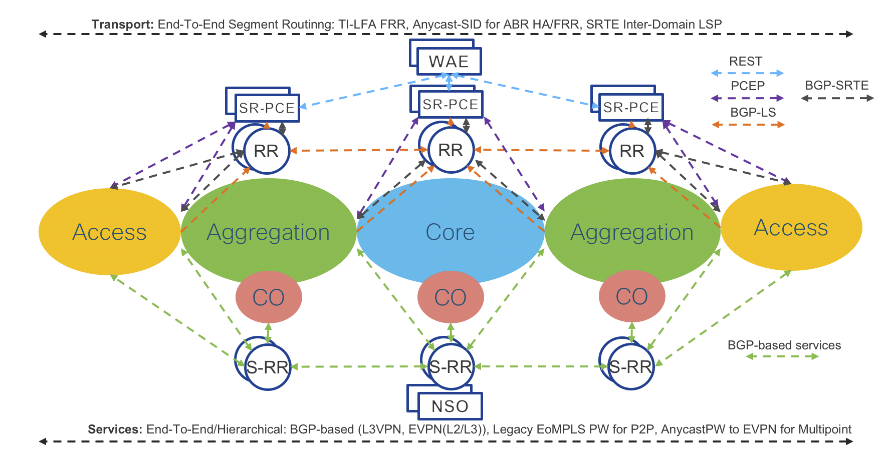
Figure 33: Compass Metro Fabric – Control-Plane
As mentioned, service provisioning is independent of the transport layer. However, transport is responsible for providing the path based on service requirements (SLA). The component that enables such integration is On-Demand Next Hop (ODN). ODN is the capability of requesting to a controller a path that satisfies specific constraints (such as low latency). This is achieved by associating an SLA tag/attribute to the path request. Upon receiving the request, the SR-PCE controller calculates the path based on the requested SLA and use PCEP or BGP-SRTE to dynamically program the Service End Point with a specific SRTE Policy.
The Compass Metro Fabric design also use MPLS Performance Management to monitor link delay/jitter/drop (RFC6374) to be able to create a Low Latency topology dynamically.
Figure 34 shows a consolidated view of Compass Metro Fabric network from a Data Plane standpoint.
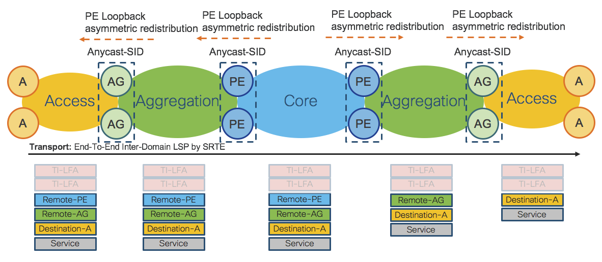
Figure 34: Compass Metro Fabric – Data-Plane
The Compass Metro Fabric Design – Phase 1
Transport - Phase 1
This section describes in detail Phase 1 of the Compass Metro Fabric design. This Phase focuses on transport programmability and BGP-based services adoption.
Figure 35 and Figure 36 show the network topology and transport Data Plane details for Phase 1. Refer also to the Access domain extension use case in Section: “Use Cases”.
The network is split into Access and Core IGP domains. Each IGP domain is represented by separate IGP processes. The Compass Metro Fabric design uses ISIS IGP protocol for validation.
Validation will be done on two types of access platforms, IOS-XR and IOS-XE, to prove interoperability.
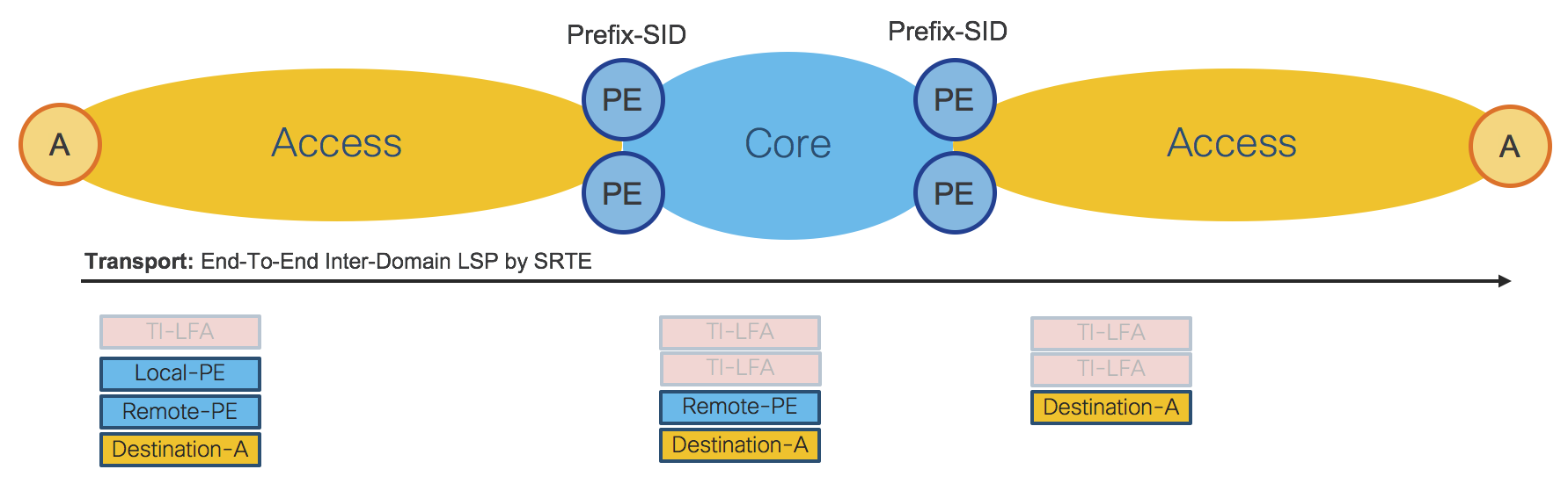
Figure 35: Access Domain Extension – End-To-End Transport
For the End-To-End LSP shown in Figure 35, the Access Router imposes 3 transport labels (SID-list) An additional label, the TI-LFA label, can be also added for FRR (node and link protection). In the Core and in the remote Access IGP Domain, 2 additional TI-LFA labels can be used for FRR (node and link protection). In Phase 1 PE ABRs are represented by Prefix-SID. Refer also to Section: “Transport Programmability - Phase 1”.
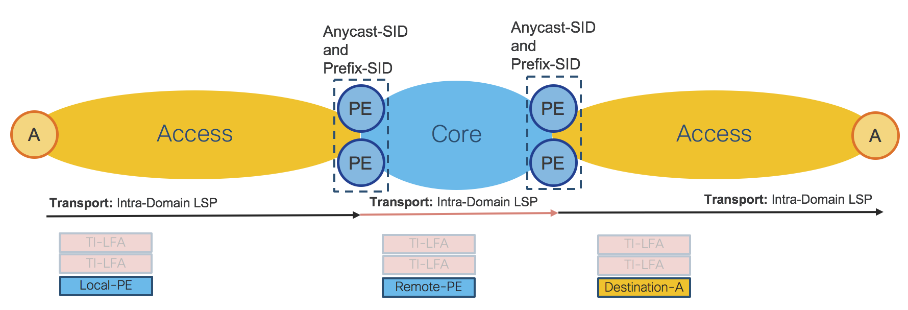
Figure 36: Access Domain Extension – Hierarchical Transport
Figure 36 shows how the Access Router imposes a single transport label to reach local PE ABRs, where the hierarchical service is terminated. Similarly, in the Core and in the remote Access IGP domain, the transport LSP is contained within the same IGP domain (Intra-Domain LSP). Routers in each IGP domain can also impose two additional TI-LFA labels for FRR (to provide node and link protection).
In the Hierarchical transport use case, PE ABRs are represented by Anycast-SID or Prefix-SID. Depending on the type of service, Anycast-SID or Prefix-SID is used for the transport LSP.
Transport Programmability – Phase 1
The Compass Metro Fabric employs a distributed and highly available SR-PCE design as described in Section: “Transport Programmability”. Transport programmability is based on PCEP. Figure 37 shows the design when SR-PCE uses PCEP.

Figure 37: SR-PCE – PCEP
SR-PCE in the Access domain is responsible for Inter-Domain LSPs and provides the SID-list. PE ABRs are represented by Prefix-SID.
SR-PCE in the Core domain is responsible for On-Demand Nexthop (ODN) for hierarchical services. Refer to the table in Figure 41 to see what services use ODN. Refer to Section: “Transport Controller - Path Computation Engine (PCE)” to see more details about XR Transport Controller (SR-PCE). Note that Phase 1 uses the “Delegated Computation to SR-PCE” mode described in Section: “Path Computation Engine - Workflow” without WAE as shown in Figure 38.
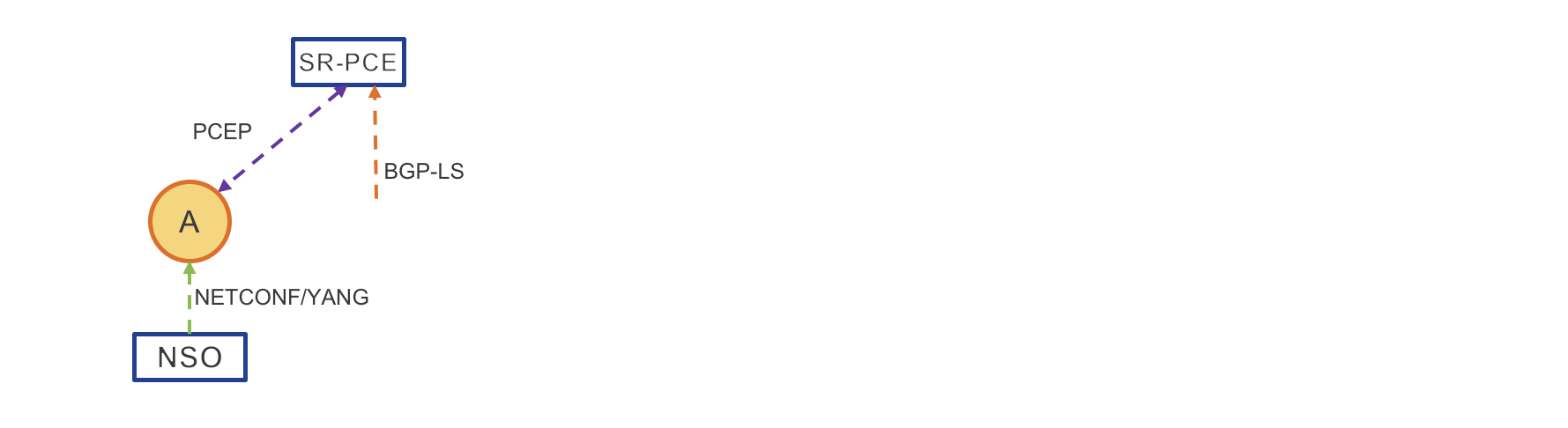
Figure 38: PCE Path Computation – Phase 1
Delegated Computation to SR-PCE
NSO provisions the service – Service can also be provisioned via CLI
Access Router requests a path
SR-PCE computes the path
SR-PCE provides the path to Access Router
Access Router confirms
Services – Phase 1
This section describes the Services used in the Compass Metro Fabric Phase 1.
The table in Figure 39 describes the End-To-End services, while the network diagram in Figure 40 shows how services are deployed in the network. Refer also to Section: “Services - Design” of this document.
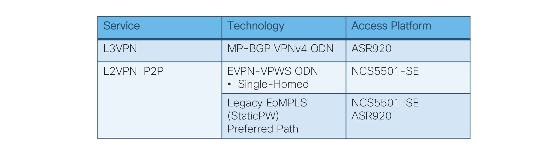
Figure 39: End-To-End Services table
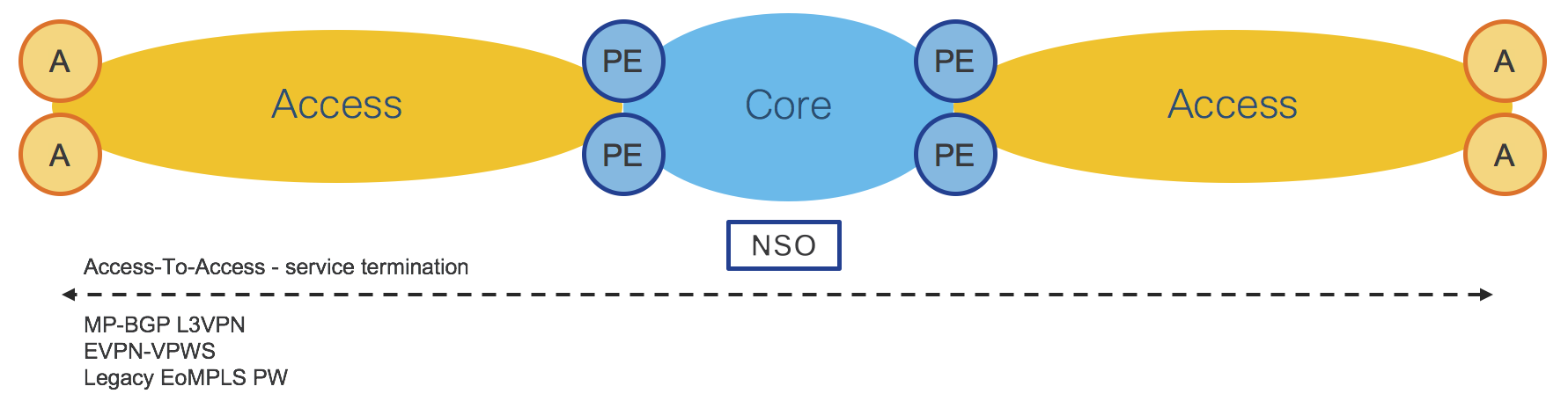
Figure 40: End-To-End Services
The table in Figure 41 describes the hierarchical services, while the network diagram in Figure 42 shows how services are deployed in the network. Refer also to Section: “Services - Design” of this document.
In addition, the table in Figure 41 shows where PE ABRs Anycast-SID is required and where ODN in the Core IGP domain is used.
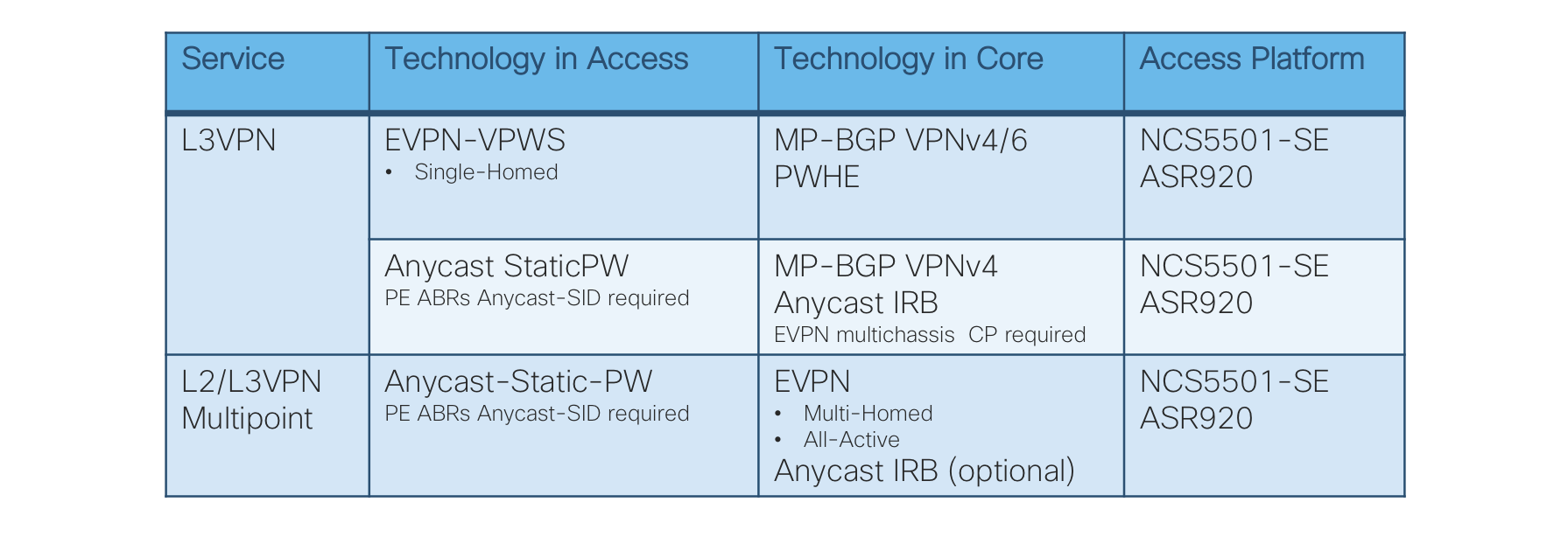
Figure 41: Hierarchical Services table
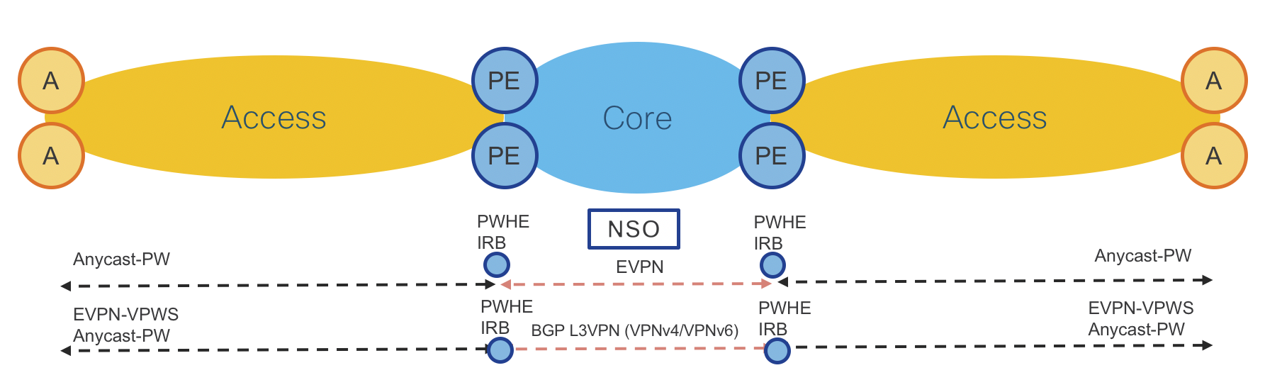
Figure 42: Hierarchical Services
The Compass Metro Fabric uses the hierarchical Services Route-Reflectors (S-RRs) design described in Section: “Services - Router-Reflector (S-RR)”. Figure 43 shows in detail the S-RRs design used for Phase 1.
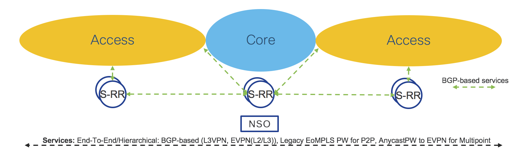
Figure 43: Services Route-Reflectors (S-RRs)
Network Services Orchestrator (NSO) is used for service provisioning. Refer to Section: “Network Services Orchestrator (NSO)”.
Transport and Services Integration – Phase 1
Transport and Services integration is described in Section: “Transport and Services Integration” of this document. Figure 44 shows an example of End-To-End LSP and services integration in Phase 1.
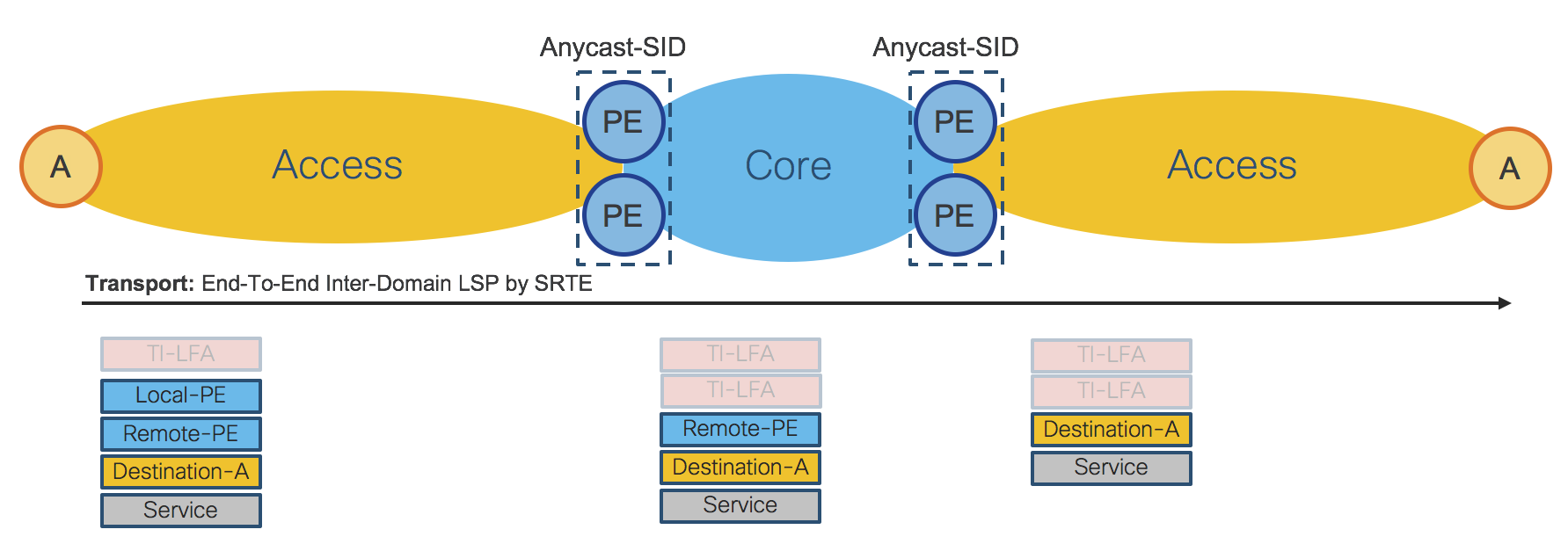
Figure 44: Transport and Services Data-Plane
Figure 45 shows a consolidated view of the Transport and Services Control-Plane.
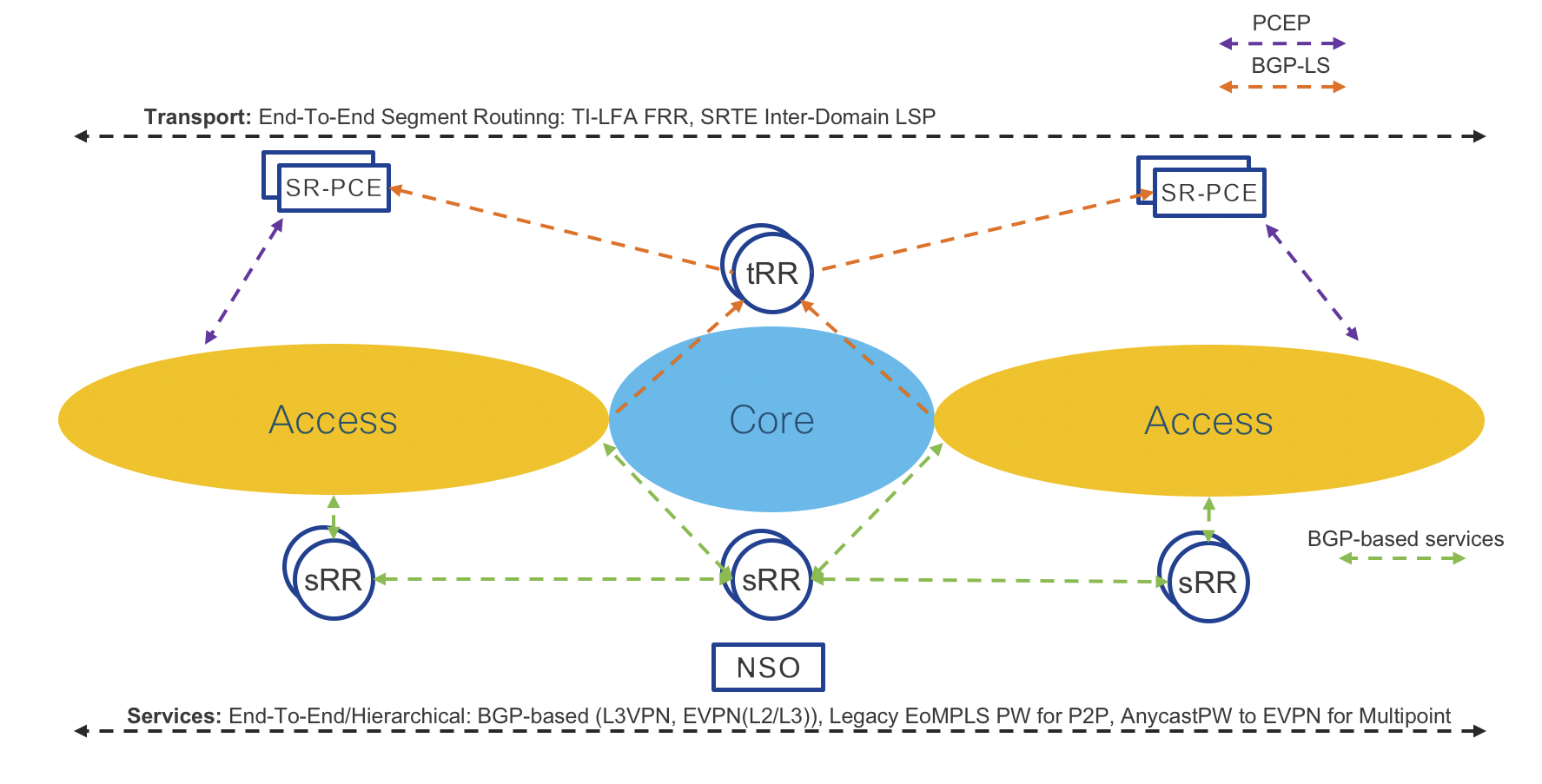
Figure 45: Transport and Services Control-Plane
Figure 46 shows the physical topology of the testbed used for Phase 1 validation.
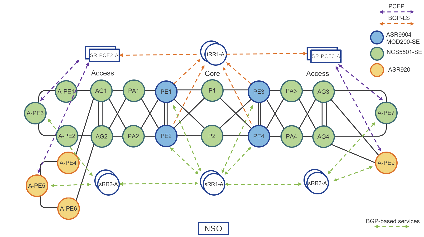
Figure 46: Testbed – Phase 1
The Compass Metro Fabric Design - Summary
The Compass Metro Fabric brings huge simplification at the Transport as well as at the Services layers of a Service Provider network. Simplification is a key factor for real Software Defined Networking (SDN). Cisco continuously improves Service Provider network designs to satisfy market needs for scalability and flexibility.
From a very well established and robust Unified MPLS design, Cisco has embarked on a journey toward transport simplification and programmability, which started with the Transport Control Plane unification in Evolved Programmable Network 5.0 (EPN5.0). The Cisco Metro Fabric provides another huge leap forward in simplification and programmability adding Services Control Plane unification and centralized path computation.
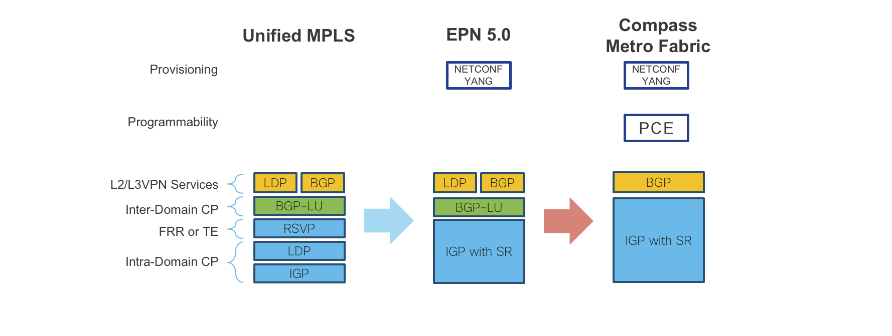
Figure 47: Compass Metro Fabric – Evolution
The transport layer requires only IGP protocols with Segment Routing extensions for Intra and Inter Domain forwarding. Fast recovery for node and link failures leverages Fast Re-Route (FRR) by Topology Independent Loop Free Alternate (TI-LFA), which is a built-in function of Segment Routing. End to End LSPs are built using Traffic Engineering by Segment Routing, which does not require additional signaling protocols. Instead it solely relies on SDN controllers, thus increasing overall network scalability. The controller layer is based on standard industry protocols like BGP-LS, PCEP, BGP-SRTE, etc., for path computation and NETCONF/YANG for service provisioning, thus providing a on open standards based solution.
For all those reasons, the Cisco Metro Fabric design really brings an exciting evolution in Service Provider Networking.
Leave a Comment