
Converged SDN Transport High Level Design v4.0
Revision History
| Version | Date | Comments |
|---|---|---|
| 1.0 | 05/08/2018 | Initial Converged SDN Transport publication |
| 1.5 | 09/24/2018 | NCS540 Access, ZTP, NSO Services |
| 2.0 | 4/1/2019 | Non-inline PE Topology, NCS-55A2-MOD, IPv4/IPv6/mLDP Multicast, LDP to SR Migration |
| 3.0 | 1/20/2020 | Converged Transport for Cable CIN, Multi-domain Multicast, Qos w/H-QoS access, MACSEC, Coherent Optic connectivity |
| 3.5 | 10/15/2020 | Unnumbered access rings, Anycast SID ABR Resiliency, E-Tree for FTTH deployments, SR Multicast using Tree-SID, NCS 560, SmartPHY for R-PHY, Performance Measurement |
| 4.0 | 2/1/2020 | SR Flexible Algorithms inc. Inter-Domain, PTP multi-profile inc. G.82751<>G.8275.2 interworking, G.8275.2 on BVI, ODN support for EVPN ELAN, TI-LFA Open Ring support, NCS 520, SR on cBR8 |
Minimum supported IOS-XR Release
| CST Version | XR version |
|---|---|
| 1.0 | 6.3.2 |
| 1.5 | 6.5.1 |
| 2.0 | 6.5.3 |
| 3.0 | 6.6.3 |
| 3.5 | 7.1.2 |
| 4.0 | 7.2.2 on NCS, 7.1.3 on ASR9K |
Minimum supported IOS-XE Release
| CST Version | XR version |
|---|---|
| 4.0 | 16.12.03 on NCS 520, ASR920; 17.03.01w |
Value Proposition
Service Providers are facing the challenge to provide next generation services that can quickly adapt to market needs. New paradigms such as 5G introduction, video traffic continuous growth, IoT proliferation and cloud services model require unprecedented flexibility, elasticity and scale from the network. Increasing bandwidth demands and decreasing ARPU put pressure on reducing network cost. At the same time, services need to be deployed faster and more cost effectively to stay competitive.
Metro Access and Aggregation solutions have evolved from native Ethernet/Layer 2 based, to Unified MPLS to address the above challenges. The Unified MPLS architecture provides a single converged network infrastructure with a common operational model. It has great advantages in terms of network convergence, high scalability, high availability, and optimized forwarding. However, that architectural model is still quite challenging to manage, especially on large-scale networks, because of the large number of distributed network protocols involved which increases operational complexity.
Converged SDN Transport design introduces an SDN-ready architecture which evolves traditional Metro network design towards an SDN enabled, programmable network capable of delivering all services (Residential, Business, 4G/5G Mobile Backhaul, Video, IoT) on the premise of simplicity, full programmability, and cloud integration, with guaranteed service level agreements (SLAs).
The Converged SDN Transport design brings tremendous value to Service Providers:
Fast service deployment and rapid time to market through fully automated service provisioning and end-to-end network programmability
Operational simplicity with less protocols to operate and manage
Smooth migration towards an SDN-ready architecture thanks to backward-compatibility with existing network protocols and services
Next generation service creation leveraging guaranteed SLAs
Enhanced and optimized operations using telemetry/analytics in conjunction with automation tools
The Converged SDN Transport design is targeted at Service Provider customers who:
Want to evolve their existing Unified MPLS Network
Are looking for an SDN ready solution
Need a simple, scalable design that can support future growth
Want a future proof architecture built using industry-leading technology
Summary
The Converged SDN Transport design satisfies the following criteria for scalable next-generation networks:
Simple: based on Segment Routing as unified forwarding plane and EVPN and L3VPN as a common BGP based services control plane
Programmable: Using SR-PCE to program end-to-end multi-domain paths across the network with guaranteed SLAs
Automated : Service provisioning is fully automated using NSO and YANG models; Analytics with model driven telemetry in conjunction with Crosswork Network Insights to
enhance operations and network visibility
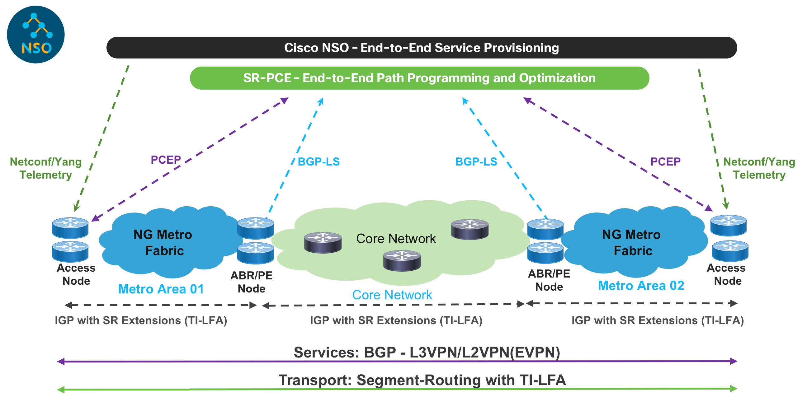
Technical Overview
The Converged SDN Transport design evolves from the successful Cisco Evolved Programmable Network (EPN) 5.0 architecture framework, to bring greater programmability and automation.
In the Converged SDN Transport design, the transport and service are built on-demand when the customer service is requested. The end-to-end inter-domain network path is programmed through controllers and selected based on the customer SLA, such as the need for a low latency path.
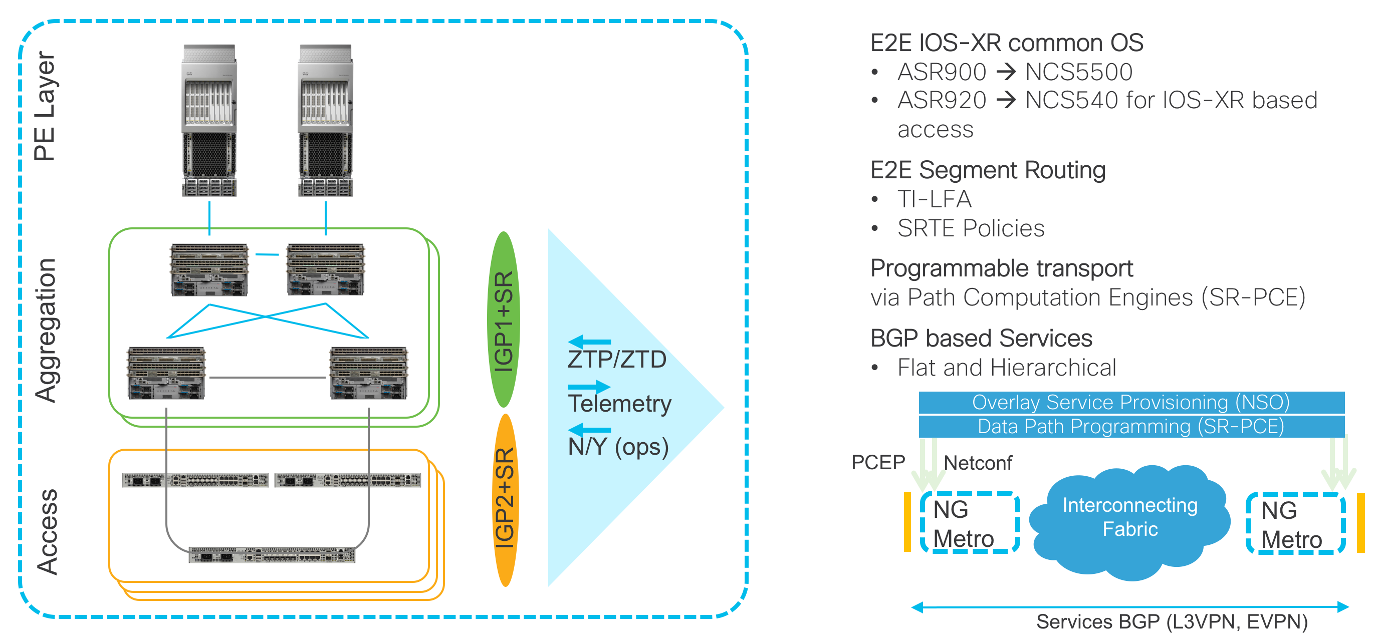
The Converged SDN Transport is made of the following main building blocks:
IOS-XR as a common Operating System proven in Service Provider Networks
Transport Layer based on Segment Routing as Unified Forwarding Plane
SDN - Segment Routing Path Computation Element (SR-PCE) as Cisco Path Computation Engine (PCE) coupled with Segment Routing to provide simple and scalable inter-domain transport connectivity, Traffic Engineering, and advanced Path control with constraints
Service Layer for Layer 2 (EVPN) and Layer 3 VPN services based on BGP as Unified Control Plane
Automation and Analytics
NSO for service provisioning
Netconf/YANG data models
Telemetry to enhance and simplify operations
Zero Touch Provisioning and Deployment (ZTP/ZTD)
Hardware Components in Design
ASR 9000
The ASR 9000 is the router of choice for high scale edge services. The Converged SDN Transport utilizes the ASR 9000 in a PE function role, performing high scale L2VPN, L3VPN, and Pseudowire headend termination. All testing up to 3.0 has been performed using Tomahawk series line cards on the ASR 9000.
NCS-560
The NCS-560 with RSP4 is a next-generation platform with high scale and modularity to fit in many access, pre-aggregation, and aggregation roles. Available in 4-slot and 7-slot versions, the NCS 560 is fully redundant with a variety of 40GE/100GE, 10GE, and 1GE modular adapters. The NCS 560 RSP4 has built-in GNSS timing support along with a high scale (-E) version to support full Internet routing tables or large VPN routing tables with room to spare for 5+ years of growth. The NCS 560 provides all of this with a very low power and space footprint with a depth of 9.5”.
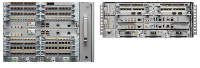
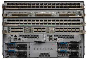
NCS 5504, 5508, 5516 Modular Chassis
The modular chassis version of the NCS 5500 is available in 4, 8, and 16 slot versions for flexible interfaces at high scale with dual RP modules. A variety of line cards are available with 10G, 40G, 100G, and 400G interface support. The NCS 5500 fully supports timing distribution for applications needing high accuracy clocks like mobile backhaul.
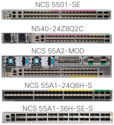
NCS-5501, NCS-5501-SE, and N540-ACC-SYS
The NCS 5501, 5501-SE, and 540 hardware is validated in both an access and aggregation role in the Converged SDN Transport. The 5501 has 48x1G/10G SFP+ and 6x100G QSFP28 interfaces, the SE adds higher route scale via an external TCAM. The N540-ACC-SYS is a next-generation access node with 24x10G SFP+, 8x25G SFP28, and 2x100G QSFP28 interfaces. The NCS540 is available in extended temperature with a conformal coating for deployment deep into access networks.
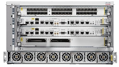
NCS-55A2-MOD
The Converged SDN Transport design now supports the NCS-55A2-MOD access and aggregation router. The 55A2-MOD is a modular 2RU router with 24 1G/10G SFP+, 16 1G/10G/25G SFP28 onboard interfaces, and two modular slots capable of 400G of throughput per slot using Cisco NCS Modular Port Adapters or MPAs. MPAs add additional 1G/10G SFP+, 100G QSFP28, or 100G/200G CFP2 interfaces. The 55A2-MOD is available in an extended temperature version with a conformal coating as well as a high scale configuration (NCS-55A2-MOD-SE-S) scaling to millions of IPv4 and IPv6 routes.
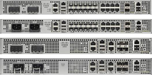
ASR 920
The IOS-XE based ASR 920 is tested within the Converged SDN Transport as an access node. The Segment Routing data plane and supported service types are validated on the ASR 920 within the CST design. Please see the services support section for all service types supported on the ASR 920.
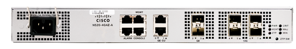
NCS 520
The IOS-XE based NCS 520 acts as an Ethernet demarcation device (NID) or carrier Ethernet switch in the Converged SDN Transport design. The MEF 3.0 certified device acts as a customer equipment termination point where QoS, OAM (Y.1731,802.3ah), and service validation/testing using Y.1564 can be performed. The NCS 520 is available in a variety of models covering different port requirements including industrial temp and conformal coated models for harsher environments.
Transport – Design Components
Network Domain Structure
To provide unlimited network scale, the Converged SDN Transport is structured into multiple IGP Domains: Access, Aggregation, and Core. However as we will illustrate in the next section, the number of domains is completely flexible based on provider need.
Refer to the network topology in Figure 1.
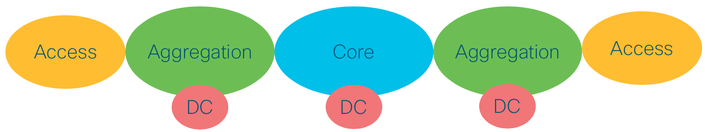
Figure 1: High scale fully distributed
The network diagram in Figure 2 shows how a Service Provider network can be simplified by decreasing the number of IGP domains. In this scenario the Core domain is extended over the Aggregation domain, thus increasing the number of nodes in the Core.

Figure 2: Distributed with expanded access
A similar approach is shown in Figure 3. In this scenario the Core domain remains unaltered and the Access domain is extended over the Aggregation domain, thus increasing the number of nodes in the Access domain.:%s/

Figure 3: Distributed with expanded core
The Converged SDN Transport transport design supports all three network options, while remaining easily customizable.
The first phase of the Converged SDN Transport, discussed later in this document, will cover in depth the scenario described in Figure 3.
Topology options and PE placement - Inline and non-inline PE
The non-inline PE topology, shown in the figure below, moves the services edge PE device from the forwarding path between the access/aggregation networks and the core. There are several factors which can drive providers to this design vs. one with an in-line PE, some of which are outlined in the table below. The control-plane configuration of the Converged SDN Transport does not change, all existing ABR configuration remains the same, but the device no longer acts as a high-scale PE.
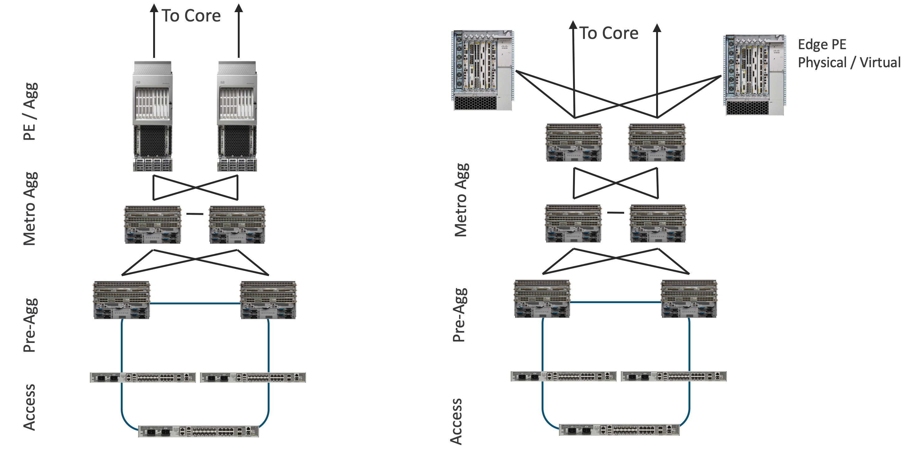 Figure: Non-Inline Aggregation Topology
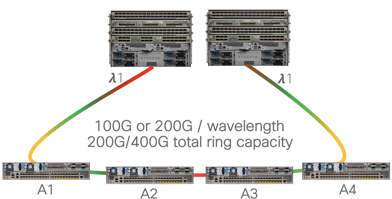
Connectivity using 100G/200G coherent optics w/MACSec
In Converged SDN Transport 3.0 we add support for the use of pluggable CFP2-DCO transceivers to enable high speed aggregation and access network infrastructure. As endpoint bandwidth increases due to technology innovation such as 5G and Remote PHY, access and aggregation networks must grow from 1G and 10G to 100G and beyond. Coherent router optics simplify this evolution by allowing an upgrade path to increase ring bandwidth up to 400Gbps without deploying costly DWDM optical line systems.
MACSec is an industry standard protocol running at L2 to provide encryption across Ethernet links. In CST 3.0 MACSec is enabled across CFP2-DCO access to aggregation links. MACSec support is hardware dependent, please consult individual hardware data sheets for MACSec support.
Ring deployment without multiplexers
In the simplest deployment access rings are deployed over dark fiber, enabling plug and play operation up to 80km without amplification.
 CFP2-DCO DWDM ring deployment
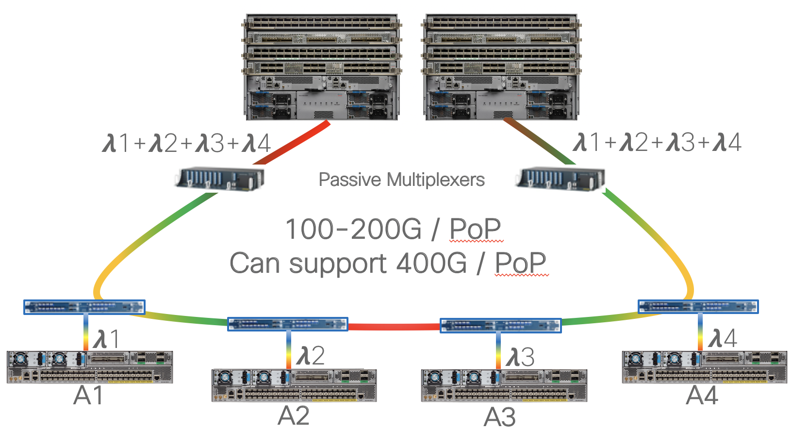
Ring deployment with multiplexer
In this option the nodes are deployed with active or passive multiplexers to maximize fiber utilization rings needing more bandwidth per ring site. While this example shows each site on the ring having direct DWDM links back to the aggregation nodes, a hybrid approach could also be supported targeting only high-bandwidth locations with direct links while leaving other sites on a an aggregation ring.
 CFP2-DCO DWDM hub and spoke or partial mesh deployment
The Cisco NCS 55A2-MOD and 55A2-MOD-SE hardened modular platform has a mix of fixed SFP+ and SFP28 ports along with two MPA slots. The coherent aggregation and access solution can utilize either the 2xCFP2-DCO MPA or 2xQSFP28+1xCFP2-DCO MPA. The same MPA modules can be used in the 5504, 5508, and 5516 chassis using the NC55-MOD-A-S and NC55-MODD-A-SE line cards, with 12xSFP+ and 2xQSFP+ ports. The NCS 560 also now supports a CFP2-DCO line card to support using DWDM links with the NCS 560.
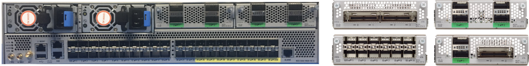 Cisco 55A2 modular hardened router
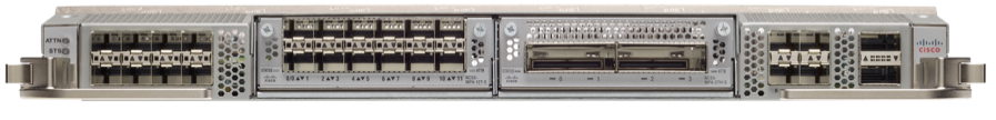 Cisco NCS 5500 chassis modular line card
Unnumbered Interface Support
In CST 3.5, starting at IOS-XR 7.1.1 we have added support for unnumbered interfaces. Using unnumbered interfaces in the network eases the burden of deploying nodes by not requiring specific IPv4 or IPv6 interface addresses between adjacent node. When inserting a new node into an existing access ring the provider only needs to configure each interface to use a Loopback address on the East and West interfaces of the nodes. IGP adjacencies will be formed over the unnumbered interfaces.
IS-IS and Segment Routing/SR-TE utilized in the Converged SDN Transport design supports using unnumbered interfaces. SR-PCE used to compute inter-domain SR-TE paths also supports the use of unnumbered interfaces. In the topology database each interface is uniquely identified by a combination of router ID and SNMP IfIndex value.
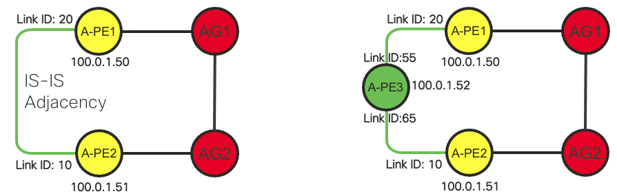 Unnumbered node insertion
Unnumbered interface configuration:
interface TenGigE0/0/0/2
 description to-AG2
 mtu 9216
 ptp
  profile My-Slave
  port state slave-only
  local-priority 10
 !
 service-policy input core-ingress-classifier
 service-policy output core-egress-exp-marking
 ipv4 point-to-point
 ipv4 unnumbered Loopback0
 frequency synchronization
  selection input
  priority 10
  wait-to-restore 1
 !
!
Intra-Domain
Intra-Domain Routing and Forwarding
The Converged SDN Transport is based on a fully programmable transport that satisfies the requirements described earlier. The foundation technology used in the transport design is Segment Routing (SR) with a MPLS based Data Plane in Phase 1 and a IPv6 based Data Plane (SRv6) in future.
Segment Routing dramatically reduces the amount of protocols needed in a Service Provider Network. Simple extensions to traditional IGP protocols like ISIS or OSPF provide full Intra-Domain Routing and Forwarding Information over a label switched infrastructure, along with High Availability (HA) and Fast Re-Route (FRR) capabilities.
Segment Routing defines the following routing related concepts:
Prefix-SID – A node identifier that must be unique for each node in a IGP Domain. Prefix-SID is statically allocated by th3 network operator.
Adjacency-SID – A node’s link identifier that must be unique for each link belonging to the same node. Adjacency-SID is typically dynamically allocated by the node, but can also be statically allocated.
In the case of Segment Routing with a MPLS Data Plane, both Prefix-SID and Adjacency-SID are represented by the MPLS label and both are advertised by the IGP protocol. This IGP extension eliminates the need to use LDP or RSVP protocol to exchange MPLS labels.
The Converged SDN Transport design uses ISIS as the IGP protocol.
Intra-Domain Forwarding - Fast Re-Route using TI-LFA
Segment-Routing embeds a simple Fast Re-Route (FRR) mechanism known as Topology Independent Loop Free Alternate (TI-LFA).
TI-LFA provides sub 50ms convergence for link and node protection. TI-LFA is completely stateless and does not require any additional signaling mechanism as each node in the IGP Domain calculates a primary and a backup path automatically and independently based on the IGP topology. After the TI-LFA feature is enabled, no further care is expected from the network operator to ensure fast network recovery from failures. This is in stark contrast with traditional MPLS-FRR, which requires RSVP and RSVP-TE and therefore adds complexity in the transport design.
Please refer also to the Area Border Router Fast Re-Route covered in Section: “Inter-Domain Forwarding - High Availability and Fast Re-Route” for additional details.
Inter-Domain
Inter-Domain Forwarding
The Converged SDN Transport achieves network scale by IGP domain separation. Each IGP domain is represented by separate IGP process on the Area Border Routers (ABRs).
Section: “Intra-Domain Routing and Forwarding” described basic Segment Routing concepts: Prefix-SID and Adjacency-SID. This section introduces the concept of Anycast SID. Segment Routing allows multiple nodes to share the same Prefix-SID, which is then called a “Anycast” Prefix-SID or Anycast-SID. Additional signaling protocols are not required, as the network operator simply allocates the same Prefix SID (thus a Anycast-SID) to a pair of nodes typically acting as ABRs.
Figure 4 shows two sets of ABRs:
Aggregation ABRs – AG
Provider Edge ABRs – PE
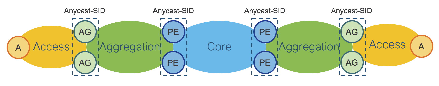
Figure 4: IGP Domains - ABRs Anycast-SID
Figure 5 shows the End-To-End Stack of SIDs for packets traveling from left to right through the network.
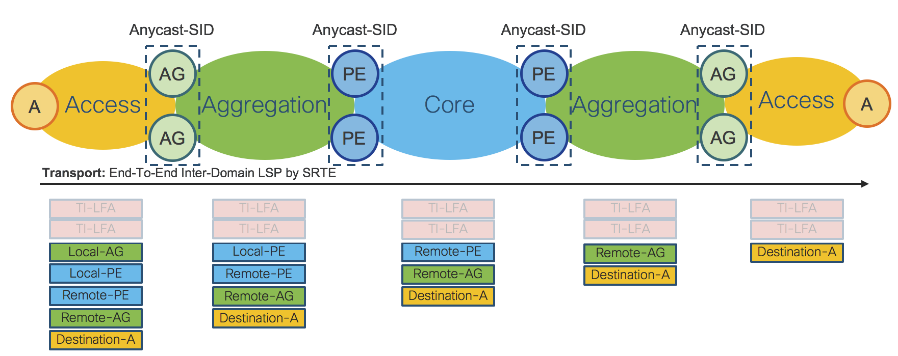
Figure 5: Inter-Domain LSP – SR-TE Policy
The End-To-End Inter-Domain Label Switched Path (LSP) was computed via Segment Routing Traffic Engineering (SR-TE) Policies.
On the Access router “A” the SR-TE Policy imposes:
Local Aggregation Area Border Routers Anycast-SID: Local-AG Anycast-SID
Local Provider Edge Area Border Routers Anycast-SID: Local-PE Anycast SID
Remote Provider Edge Area Border Routers Anycast-SID: Remote-PE Anycast-SID
Remote Aggregation Area Border Routers Anycast-SID: Remote-AG Anycast-SID
Remote/Destination Access Router: Destination-A Prefix-SID: Destination-A Prefix-SID
The SR-TE Policy is programmed on the Access device on-demand by an external Controller and does not require any state to be signaled throughout the rest of the network. The SR-TE Policy provides, by simple SID stacking (SID-List), an elegant and robust way to program Inter-Domain LSPs without requiring additional protocols such as BGP-LU (RFC3107).
Please refer to Section: “Transport Programmability” for additional details.
Area Border Routers – Prefix-SID vs Anycast-SID
Section: “Inter-Domain Forwarding” showed the use of Anycast-SID at the ABRs for the provisioning of an Access to Access End-To-End LSP. When the LSP is set up between the Access Router and the AG/PE ABRs, there are two options:
ABRs are represented by Anycast-SID; or
Each ABR is represented by a unique Prefix-SID.
Choosing between Anycast-SID or Prefix-SID depends on the requested service and inclusion of Anycast SIDs in the SR-TE Policy. Please refer to Section: “Services - Design”. If one is using the SR-PCE, such as the case of ODN SR-TE paths, the inclusion of Anycast SIDs is done via configuration.
Note that both options can be combined on the same network.
Inter-Domain Forwarding - High Availability and Fast Re-Route
AG/PE ABRs redundancy enables high availability for Inter-Domain Forwarding.
Figure 7: IGP Domains - ABRs Anycast-SID
When Anycast-SID is used to represent AG or PE ABRs, no other mechanism is needed for Fast Re-Route (FRR). Each IGP Domain provides FRR independently by TI-LFA as described in Section: “Intra-Domain Forwarding - Fast Re-Route”.
Figure 8 shows how FRR is achieved for a Inter-Domain LSP.
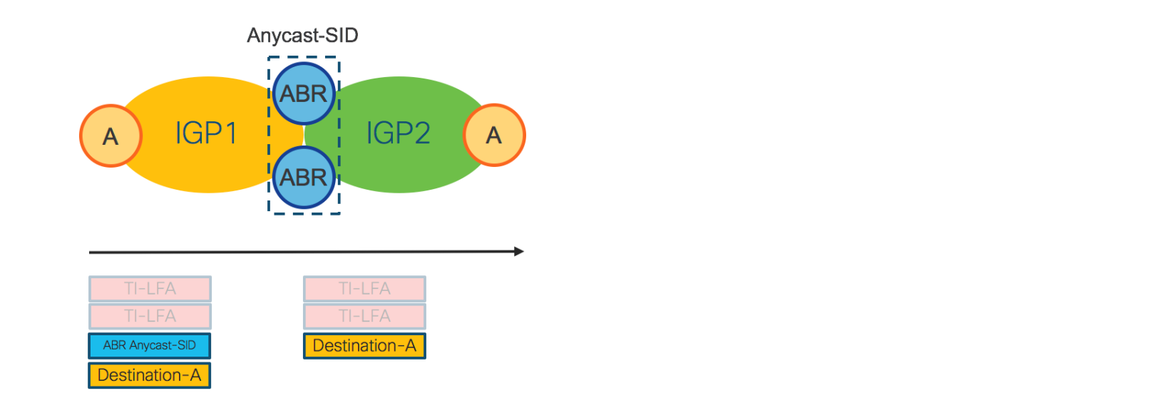
Figure 8: Inter-Domain - FRR
The access router on the left imposes the Anycast-SID of the ABRs and the Prefix-SID of the destination access router. For FRR, any router in IGP1, including the Access router, looks at the top label: “ABR Anycast-SID”. For this label, each device maintains a primary and backup path preprogrammed in the HW. In IGP2, the top label is “Destination-A”. For this label, each node in IGP2 has primary and backup paths preprogrammed in the HW. The backup paths are computed by TI-LFA.
As Inter-Domain forwarding is achieved via SR-TE Policies, FRR is completely self-contained and does not require any additional protocol.
Note that when traditional BGP-LU is used for Inter-Domain forwarding, BGP-PIC is also required for FRR.
Inter-Domain LSPs provisioned by SR-TE Policy are protected by FRR also in case of ABR failure (because of Anycast-SID). This is not possible with BGP-LU/BGP-PIC, since BGP-LU/BGP-PIC have to wait for the IGP to converge first.
SR Data Plane Monitoring provides proactive method to ensure reachability between all SR enabled nodes in an IGP domain. SR DPM utilizes well known MPLS OAM capabilities with crafted SID lists to ensure valid forwarding across the entire IGP domain. See the CST Implementation Guide for more details on SR Data Plane monitoring.
Inter-Domain Open Ring Support
Prior to CST 4.0 and XR 7.2.1, the use of TI-LFA within a ring topology required the ring be closed within the IGP domain. This required an interconnect at the ASBR domain node for each IGP domain terminating on the ASBR. This type of connectivity was not always possible in an aggregation network due to fiber or geographic constraints. In CST 4.0 we have introduced support for open rings by utilizing MPLSoGRE tunnels between terminating boundary nodes across the upstream IGP domain. The following picture illustrates open ring support between an access and aggregation network.
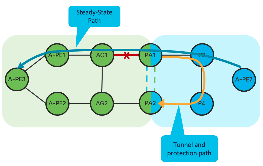
In the absence of a physical link between the boundary nodes PA1 and PA2, GRE tunnels can be created to interconnect each domain over its adjacent domain. During a protection event, such as the link failure between PA1 and GA1, traffic will enter the tunnel on the protection node, in this case PA1 towards PA2. Keep in mind traffic will loop back through the domain until re-convergence occurs. In the case of a core failure, bandwidth may not be available in an access ring to carry all core traffic, so care must be taken to determine traffic impact.
Transport Programmability
Figure 9 and Figure 10 show the design of Route-Reflectors (RR), Segment Routing Path Computation Element (SR-PCE) and WAN Automation Engines (WAE). High-Availability is achieved by device redundancy in the Aggregation and Core networks.
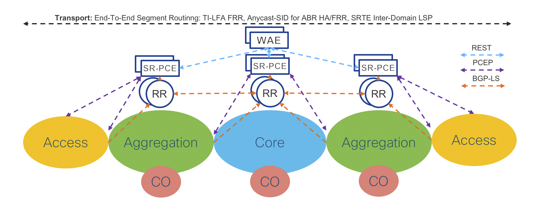
Figure 9: Transport Programmability – PCEP
Transport RRs collect network topology from ABRs through BGP Link State (BGP-LS). Each Transport ABR has a BGP-LS session with the two Domain RRs. Each domain is represented by a different BGP-LS instance ID.
Aggregation Domain RRs collect network topology information from the Access and the Aggregation IGP Domain (Aggregation ABRs are part of the Access and the Aggregation IGP Domain). Core Domain RRs collect network topology information from the Core IGP Domain.
Aggregation Domain RRs have BGP-LS sessions with Core RRs.
Through the Core RRs, the Aggregation Domains RRs advertise local Aggregation and Access IGP topologies and receive the network topologies of the remote Access and Aggregation IGP Domains as well as the network topology of the Core IGP Domain. Hence, each RR maintains the overall network topology in BGP-LS.
Redundant Domain SR-PCEs have BGP-LS sessions with the local Domain RRs through which they receive the overall network topology. Refer to Section: “Segment Routing Path Computation Element (SR-PCE)” for more details about SR-PCE.
SR-PCE is capable of computing the Inter-Domain LSP path on-demand. The computed path (Segment Routing SID List) is communicated to the Service End Points via a Path Computation Element Protocol (PCEP) response as shown in Figure 9.
The Service End Points create a SR-TE Policy and use the SID list returned by SR-PCE as the primary path.
Service End Points can be located on the Access Routers for Flat Services or at both the Access and domain PE routers for Hierarchical Services. The domain PE routers and ABRs may or may not be the same router. The SR-TE Policy Data Plane in the case of Service End Point co-located with the Access router was described in Figure 5.
The proposed design is very scalable and can be easily extended to support even higher numbers of PCEP sessions by adding additional RRs and SR-PCE elements into the Access Domain.
Figure 11 shows the Converged SDN Transport physical topology with examples of product placement.
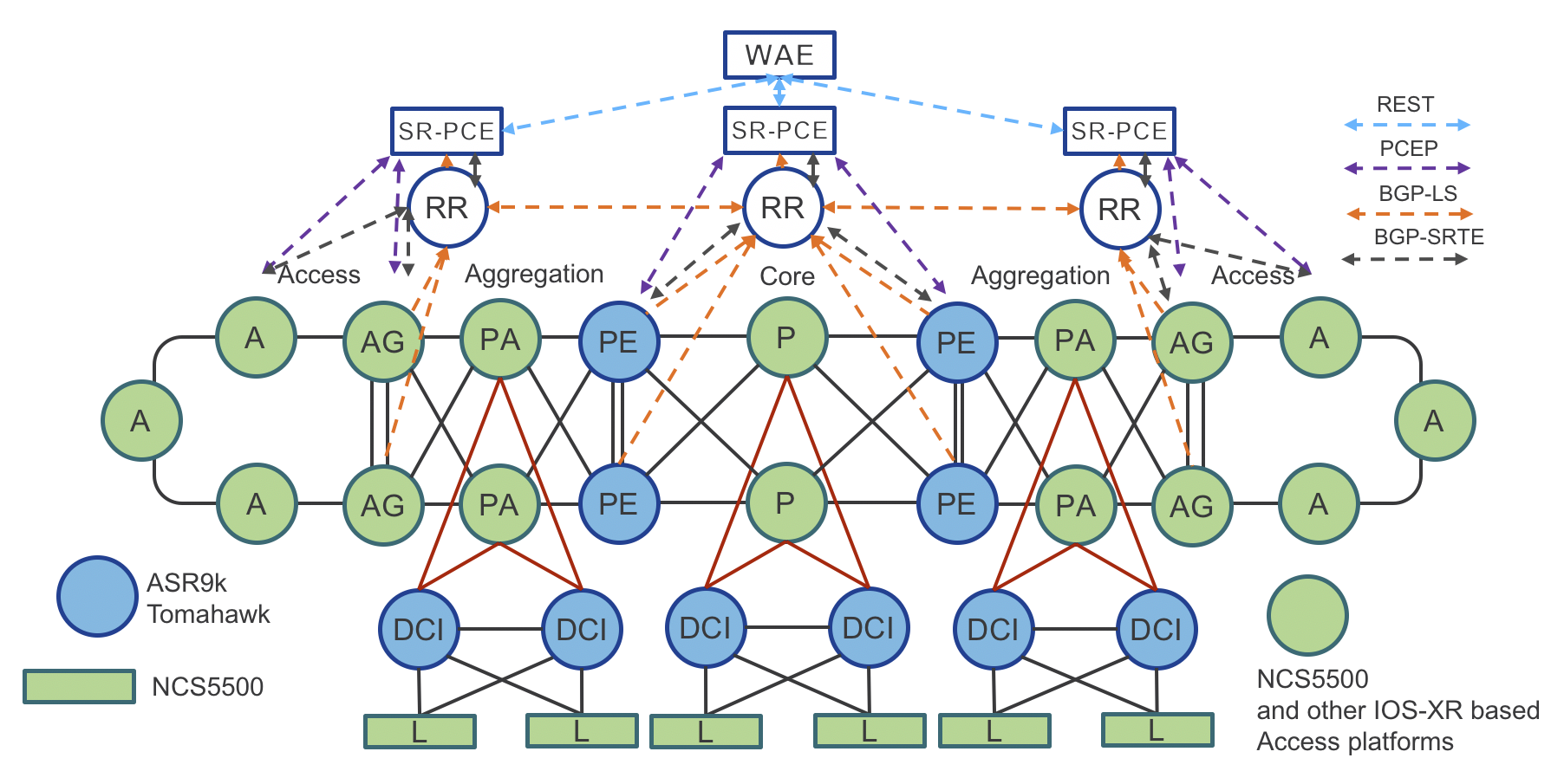
Figure 11: Converged SDN Transport – Physical Topology with transport programmability
Traffic Engineering (Tactical Steering) – SR-TE Policy
Operators want to fully monetize their network infrastructure by offering differentiated services. Traffic engineering is used to provide different paths (optimized based on diverse constraints, such as low-latency or disjoined paths) for different applications. The traditional RSVP-TE mechanism requires signaling along the path for tunnel setup or tear down, and all nodes in the path need to maintain states. This approach doesn’t work well for cloud applications, which have hyper scale and elasticity requirements.
Segment Routing provides a simple and scalable way of defining an end-to-end application-aware traffic engineering path known as an SR-TE Policy. The SR-TE Policy expresses the intent of the applications constraints across the network.
In the Converged SDN Transport design, the Service End Point uses PCEP along with Segment Routing On-Demand Next-hop (SR-ODN) capability, to request from the controller a path that satisfies specific constraints (such as low latency). This is done by associating SLA tags/attributes to the path request. Upon receiving the request, the SR-PCE controller calculates the path based on the requested SLA, and uses PCEP to dynamically program the ingress node with a specific SR-TE Policy.
Traffic Engineering - Dynamic Anycast-SID Paths and Black Hole Avoidance
As shown in Figure 7, inter-domain resilience and load-balancing is satisfied by using the same Anycast SID on each boundary node. Starting in CST 3.5 Anycast SIDs are used by a centralized SR-PCE without having to define an explicit SID list. Anycast SIDs are learned via the topology information distributed to the SR-PCE using BGP-LS. Once the SR-PCE knows the location of a set of Anycast SIDs, it will utilize the SID in the path computation to an egress node. The SR-PCE will only utilize the Anycast SID if it has a valid path to the next SID in the computed path, meaning if one ABR loses it’s path to the adjacent domain, the SR-PCE will update the head-end path with one utilizing a normal node SID to ensure traffic is not blackhole.
It is also possible to withdraw an anycast SID from the topology by using the conditional route advertisement feature for IS-IS, new in 3.5. Once the anycast SID Loopback has been withdrawn, it will no longer be used in a SR Policy path. Conditional route advertisement can be used for SR-TE Policies with Anycast SIDs in either dynamic or static SID candidate paths. Conditional route advertisement is implemented by supplying the router with a list of remote prefixes to monitor for reachability in the RIB. If those routes disappear from the RIB, the interface route will be withdrawn. Please see the CST Implementation Guide for instructions on configuring anycast SID inclusion and blackhole avoidance.
Transport Controller Path Computation Engine (PCE)
Segment Routing Path Computation Element (SR-PCE)
Segment Routing Path Computation Element, or SR-PCE, is a Cisco Path Computation Engine (PCE) and is implemented as a feature included as part of Cisco IOS-XR operating system. The function is typically deployed on a Cisco IOS-XR cloud appliance XRv-9000, as it involves control plane operations only. The SR-PCE gains network topology awareness from BGP-LS advertisements received from the underlying network. Such knowledge is leveraged by the embedded multi-domain computation engine to provide optimal path information to Path Computation Element Clients (PCCs) using the Path Computation Element Protocol (PCEP).
The PCC is the device where the service originates (PE) and therefore it requires end-to-end connectivity over the segment routing enabled multi-domain network.
The SR-PCE provides a path based on constraints such as:
Shortest path (IGP metrics).
Traffic-Engineering metrics.
Disjoint paths starting on one or two nodes.
Latency
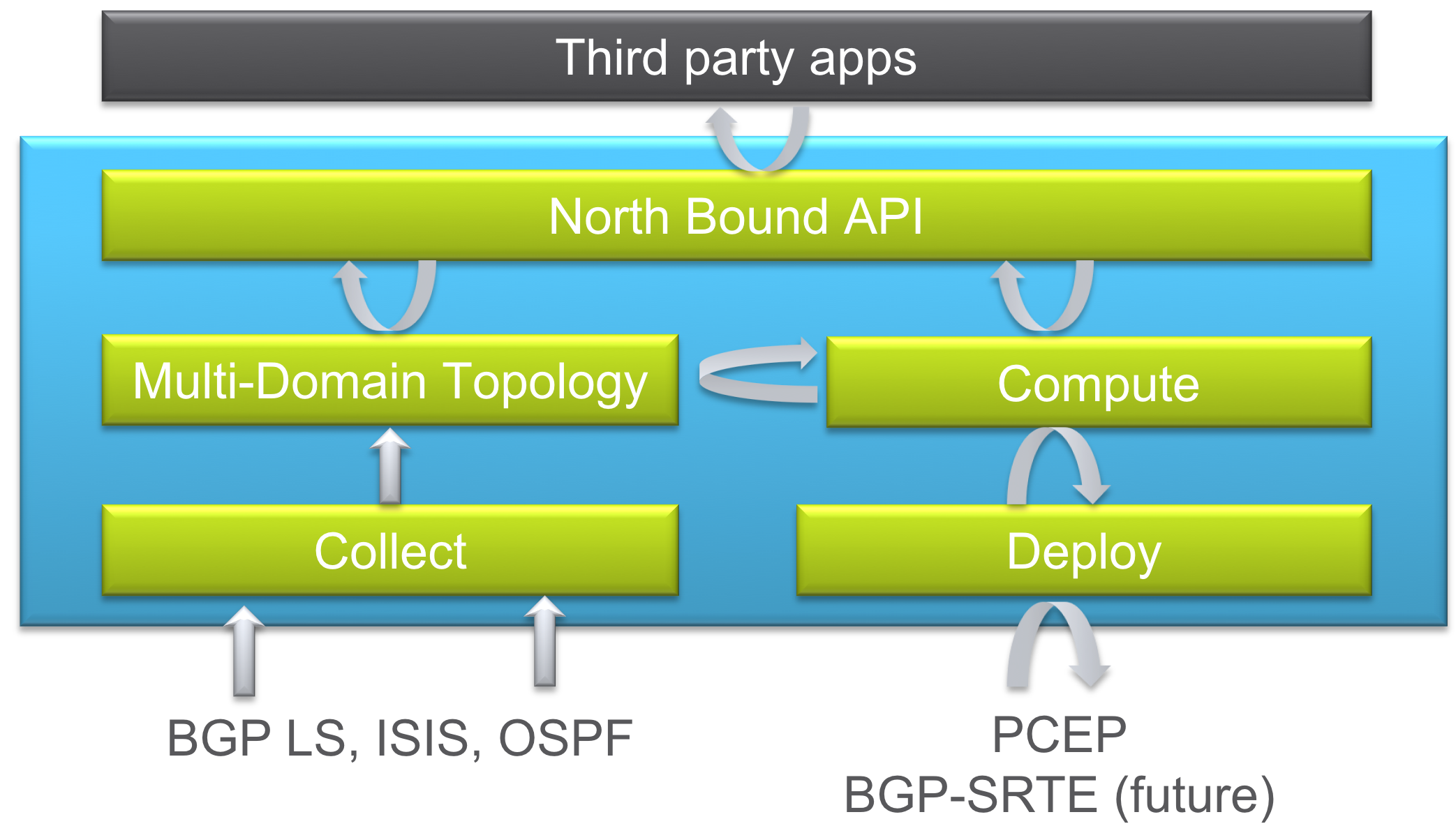
Figure 12: XR Transport Controller – Components
PCE Controller Summary – SR-PCE
Segment Routing Path Computation Element (SR-PCE):
- Runs as a feature on a physical or virtual IOS-XR node
- Collects topology from BGP using BGP-LS, ISIS, or OSPF
- Deploys SR Policies based on client requests
- Computes Shortest, Disjoint, Low Latency, and Avoidance paths
- North Bound interface with applications via REST API
Converged SDN Transport Path Computation Workflows
Static SR-TE Policy Configuration
NSO provisions the service. Alternatively, the service can be provisioned via CLI
SR-TE Policy is configured via NSO or CLI on the access node to the other service end points, specifying pcep as the computation method
Access Router requests a path from SR-PCE with metric type and constraints
SR-PCE computes the path
SR-PCE provides the path to Access Router
Access Router acknowledges and installs the SR Policy as the forwarding path for the service.
On-Demand Next-Hop Driven Configuration
NSO provisions the service. Alternatively, the service can be provisioned via CLI
On-demand colors are configured on each node, specifying specific constraints and pcep as the dynamic computation method
On reception of service routes with a specific ODN color community, Access Router requests a path from SR-PCE to the BGP next-hop as the SR-TE endpoint.
SR-PCE computes the path
SR-PCE provides the path to Access Router
Access Router acknowledges and installs the SR Policy as the forwarding path for the service.
Segment Routing Flexible Algorithms (Flex-Algo)
A powerful tool used to create traffic engineered Segment Routing paths is SR Flexible Algorithms, better known as SR Flex-Algo. Flex-Algo assigns a specific set of “algorithms” to a Segment. The algorithm identifies a specific computation constraint the segment supports. There are standards based algorithm definitions such as least cost IGP path and latency, or providers can define their own algorithms to satisfy their business needs. CST 4.0 supports computation of Flex-Algo paths in intra-domain and inter-domain deployments. In CST 4.0 (IOS-XR 7.2.2) inter-domain Flex-Algo using SR-PCE is limited to IGP lowest metric path computation.
Flex-Algo limits the computation of a path to only those nodes participating in that algorithm. This gives a powerful way to create multiple network domains within a single larger network, constraining an SR path computation to segments satisfying the metrics defined by the algorithm. As you will see, we can now use a single node SID to reach a node via a path satisfying an advanced constraint such as delay.
Flex-Algo Node SID Assignment
Nodes participating in a specific algorithm must have a unique node SID prefix assigned to the algorithm. In a typical deployment, the same Loopback address is used for multiple algorithms. IGP extensions advertise algorithm membership throughout the network. Below is an example of a node with multiple algorithms and node SID assignments. By default, the basic IGP path computation is assigned to algorithm “0”. Algorithm “1” is also reserved. Algorithms 128-255 are user-definable. All Flex-Algo SIDs belong to the same global SRGB so providers deploying SR should take this into account. Each algorithm should be assigned its own block of SIDs within the SRGB, in the case below the SRGB is 16000-32000, each algorithm is assigned 1000 SIDs.
 interface Loopback0
  address-family ipv4 unicast
   prefix-sid index 150
   prefix-sid algorithm 128 absolute 18003
   prefix-sid algorithm 129 absolute 19003
   prefix-sid algorithm 130 absolute 20003
Flex-Algo IGP Definition
Flexible algorithms being used within a network must be defined in the IGP domains in the network The configuration is typically done on at least one node under the IGP configuration for domain. Under the definition the metric type used for computation is defined along with any link affinities. Link affinities are used to constrain the algorithm to not only specific nodes, but also specific links. These affinities are the same previously used by RSVP-TE.
Note: Inter-domain Flex-Algo path computation requires synchronized Flex-Algo definitions across the end-to-end path
 flex-algo 130
  metric-type delay
  advertise-definition
 !
 flex-algo 131
  advertise-definition
  affinity exclude-any red
Path Computation across SR Flex-Algo Network
Flex-Algo works by creating a separate topology for each algorithm. By default, all links interconnecting nodes participating in the same algorithm can be used for those paths. If the algorithm is defined to include or exclude specific link affinities, the topology will reflect it. A SR-TE path computation using a specific Flex-Algo will use the Algo’s topology for end the end path computation. It will also look at the metric type defined for the Algo and use it for the path computation. Even with a complex topology, a single SID is used for the end to end path, as opposed to using a series of node and adjacency SIDs to steer traffic across a shared topology. Each node participating in the algorithm has adjacencies to other nodes utilizing the same algorithm, so when a incoming MPLS label matching the algo SID enters, it will utilize the path specific to the algo. A Flex-Algo can also be used as a constraint in an ODN policy.
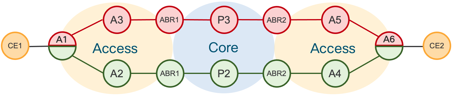
Flex-Algo Dual-Plane Example
A very simple use case for Flex-Algo is to easily define a dual-plane network topology where algorithm 129 red and algorithm 130 is green. Nodes A1 and A6 participate in both algorithms. When a path request is made for algorithm 129, the head-end nodes A1 and A6 will only use paths specific to the algorithm. The SR-TE Policy does not need to reference the specific SID, only the Algo being used as the constraints. The local node or SR-PCE will utilize the Algo to compute the path dynamically.
The following policy configuration is an example of constraining the path to the Algo 129 “Red” path.
segment-routing
 traffic-eng
  policy GREEN-PE8-128
   color 1128 end-point ipv4 100.0.2.53
   candidate-paths
    preference 1
     dynamic
      pcep
      !
      metric
       type igp
      !
     !
     constraints
      segments
       sid-algorithm 129
Segment Routing and Unified MPLS (BGP-LU) Co-existence
Summary
In the Converged SDN Transport 3.0 design we introduce validation for the co-existence of services using BGP Labeled Unicast transport for inter-domain forwarding and those using SR-TE. Many networks deployed today have an existing BGP-LU design which may not be easily migrated to SR, so graceful introduction between the two transport methods is required. In the case of a multipoint service such as EVPN ELAN or L3VPN, an endpoint may utilize BGP-LU to one endpoint and SR-TE to another.
ABR BGP-LU design
In a BGP-LU design each IGP domain or ASBR boundary node will exchange BGP labeled prefixes between domains while resetting the BGP next-hop to its own loopback address. The labeled unicast label will change at each domain boundary across the end to end network. Within each IGP domain, a label distribution protocol is used to supply MPLS connectivity between the domain boundary and interior nodes. In the Converged SDN Transport design, IS-IS with SR-MPLS extensions is used to provide intra-domain MPLS transport. This ensures within each domain BGP-LU prefixes are protected using TI-LFA.
The BGP-LU design utilized in the Converged SDN Transport validation is based on Cisco’s Unified MPLS design used in EPN 4.0. More information can be found at: <a href=https://www.cisco.com/c/dam/en/us/td/docs/solutions/Enterprise/Mobility/EPN/4_0/EPN_4_Transport_Infrastructure_DIG.pdf></a>
Quality of Service and Assurance
Overview
Quality of Service is of utmost importance in today’s multi-service converged networks. The Converged SDN Transport design has the ability to enforce end to end traffic path SLAs using Segment Routing Traffic Engineering. In addition to satisfying those path constraints, traditional QoS is used to make sure the PHB (Per-Hop Behavior) of each packet is enforced at each node across the converged network.
NCS 540, 560, and 5500 QoS Primer
Full details of the NCS 540 and 5500 QoS capabilities and configuration can be found at: <a href=https://www.cisco.com/c/en/us/td/docs/iosxr/ncs5500/qos/66x/b-qos-cg-ncs5500-66x/b-qos-cg-ncs5500-66x_chapter_010.html></a>
The NCS platforms utilize the same MQC configuration for QoS as other IOS-XR platforms but based on their hardware architecture use different elements for implementing end to end QoS. On these platforms ingress traffic is:
- Matched using flexible criteria via Class Maps
- Assigned to a specific Traffic Class (TC) and/or QoS Group for further treatment on egress
- Has its header marked with a specific IPP, DSCP, or MPLS EXP value
Traffic Classes are used internally for determining fabric priority and as the match condition for egress queuing. QoS Groups are used internally as the match criteria for egress CoS header re-marking. IPP/DSCP marking and re-marking of ingress MPLS traffic is done using ingress QoS policies. MPLS EXP for imposed labels can be done on ingress or egress, but if you wish to rewrite both the IPP/DSCP and set an explicit EXP for imposed labels, the MPLS EXP must be set on egress.
The priority-level command used in an egress QoS policy specifies the egress transmit priority of the traffic vs. other priority traffic. Priority levels can be configured as 1-7 with 1 being the highest priority. Priority level 0 is reserved for best-effort traffic.
Please note, multicast traffic does not follow the same constructs as unicast traffic for prioritization. All multicast traffic assigned to Traffic Classes 1-4 are treated as Low Priority and traffic assigned to 5-6 treated as high priority.
Hierarchical Edge QoS
Hierarchical QoS enables a provider to set an overall traffic rate across all services, and then configure parameters per-service via a child QoS policy where the percentages of guaranteed bandwidth are derived from the parent rate
H-QoS platform support
NCS platforms support 2-level and 3-level H-QoS. 3-level H-QoS applies a policer (ingress) or shaper (egress) to a physical interface, with each sub-interface having a 2-level H-QoS policy applied. Hierarchical QoS is not enabled by default on the NCS 540 and 5500 platforms. H-QoS is enabled using the hw-module profile qos hqos-enable command. Once H-QoS is enabled, the number of priority levels which can be assigned is reduced from 1-7 to 1-4. Additionally, any hierarchical QoS policy assigned to a L3 sub-interface using priority levels must include a “shape” command.
The ASR9000 supports multi-level H-QoS at high scale for edge aggregation function. In the case of hierarchical services, H-QoS can be applied to PWHE L3 interfaces.
CST Core QoS mapping with five classes
QoS designs are typically tailored for each provider, but we introduce a 5-level QoS design which can fit most provider needs. The design covers transport of both unicast and multicast traffic.
| Traffic Type | Core Marking | Core Priority | Comments |
|---|---|---|---|
| Network Control | EXP 6 | Highest | Underlay network control plane |
| Low latency | EXP 5 | Highest | Low latency service, consistent delay |
| High Priority 1 | EXP 3 | Medium-High | High priority service traffic |
| Medium Priority / Multicast | EXP 2 | Medium priority and multicast | |
| Best Effort | EXP 0 | General user traffic |
Example Core QoS Class and Policy Maps
These are presented for reference only, please see the implementation guide for the full QoS configuration
Class maps for ingress header matching
class-map match-any match-ef-exp5
 description High priority, EF
 match dscp 46
 end-class-map
!
class-map match-any match-cs5-exp4
 description Second highest priority
 match dscp 40
 end-class-map
Ingress QoS policy
policy-map ingress-classifier
 class match-ef-exp5
  set traffic-class 2
  set qos-group 2
 !
 class match-cs5-exp4
  set traffic-class 3
  set qos-group 3
 !
 class class-default
  set traffic-class 0
  set dscp 0
  set qos-group 0
 !
 end-policy-map
Class maps for egress queuing and marking policies
class-map match-any match-traffic-class-2
 description "Match highest priority traffic-class 2"
 match traffic-class 2
 end-class-map
!
class-map match-any match-traffic-class-3
 description "Match high priority traffic-class 3"
 match traffic-class 3
 end-class-map
!
class-map match-any match-qos-group-2
 match qos-group 2
 end-class-map
!
class-map match-any match-qos-group-3
 match qos-group 3
 end-class-map
Egress QoS queuing policy
policy-map egress-queuing
 class match-traffic-class-2
  priority level 2
 !
 class match-traffic-class-3
  priority level 3
 !
 class class-default
 !
 end-policy-map
Egress QoS marking policy
policy-map core-egress-exp-marking
 class match-qos-group-2
  set mpls experimental imposition 5
 !
 class match-qos-group-3
  set mpls experimental imposition 4
 class class-default
  set mpls experimental imposition 0
 !
 end-policy-map
Converged SDN Transport Use Cases
Service Provider networks must adopt a very flexible design that satisfy any to any connectivity requirements, without compromising in stability and availability. Moreover, transport programmability is essential to bring SLA awareness into the network.
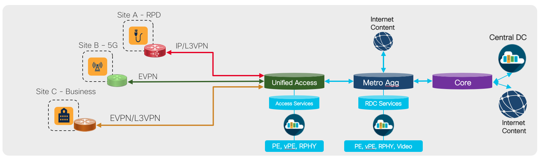
The goal of the Converged SDN Transport is to provide a flexible network blueprint that can be easily customized to meet customer specific requirements. This blueprint must adapt to carry any service type, for example
cable access, mobile, and business services over the same converged network infrastructure. The following sections highglight some specific customer use cases and the components of the design used in building those solutions.
5G Mobile Networks
Summary and 5G Service Types
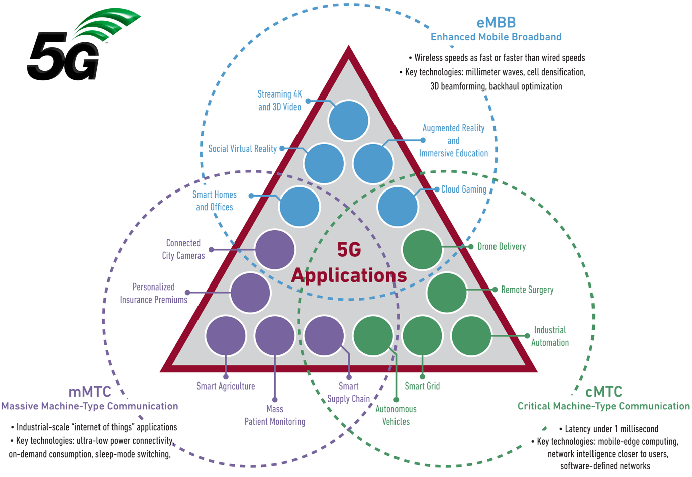
The Converged SDN Transport design introduces initial support for 5G networks and 5G services. There are a variety of new service use cases being defined by 3GPP for use on 5G networks, illustrated by the figure below. Networks must now be built to support the stringent SLA requirements of Ultra-Reliable Low-Latency services while also being able to cope with the massive bandwidth introduced by Enhanced Mobile Broadband services. The initial support for 5G in the Converged SDN Transport design focuses on the backhaul and midhaul portions of the network utilizing end to end Segment Routing. The design introduces no new service types, the existing scalable L3VPN and EVPN based services using BGP are sufficient for carrying 5G control-plane and user-plane traffic.
Key Validated Components
The following key features have been added to the CST validated design to support 5G deployments
End to End Timing Validation
End to end timing using PTP with profiles G.8275.1 and G.8275.2 have been validated in the CST design. Best practice configurations are available in the online configurations and CST Implementation Guide. It is recommended to use G.8257.1 when possible to main the highest level of accuracy across the network. In CST 4.0+ we include validation for G.8275.1 to G.8275.2 interworking, allowing the use of different profiles across the network. Synchronous Ethernet (SyncE) is also recommended across the network to maintain stability when timing to the PRC. All nodes used in the CST design support SyncE.
Low latency SR-TE path computation
In this release of the CST design, we introduce a new validated constraint type for SR-TE paths used for carrying services across the network. The “latency” constraint used either with a configured SR Policy or ODN SR Policy specifies the computation engine to look for the lowest latency path across the network. The latency computation algorithm can use different mechanisms for computing the end to end path. The first and preferred mechanism is to use the realtime measured per-link one-way delay across the network. This measured information is distributed via IGP extensions across the IGP domain and then onto external PCEs using BGP-LS extensions for use in both intra-domain and inter-domain calculations. In version 3.0 of the CST this is supported on ASR9000 links using the Performance Measurement link delay feature. More detail on the configuration can be found at https://www.cisco.com/c/en/us/td/docs/routers/asr9000/software/asr9k-r7-0/segment-routing/configuration/guide/b-segment-routing-cg-asr9000-70x/b-segment-routing-cg-asr9000-70x_chapter_010000.html#id_118505. In release 6.6.3 NCS 540 and NCS 5500 nodes support the configuration of static link-delay values which are distributed using the same method as the dynamic values. Two other metric types can also be utilized as part of the “latency” path computation. The TE metric, which can be defined on all SR IS-IS links and the regular IGP metric can be used in the absence of the link-delay metric.
Dynamic Link Performance Measurement
Starting in version 3.5 of the CST, dynamic measurement of one-way and two-way latency on logical links is fully supported across all devices. The delay measurement feature utilizes TWAMP-Lite as the transport mechanism for probes and responses. PTP is a requirement for accurate measurement of one-way latency across links and is recommended for all nodes. In the absence of PTP a “two-way” delay mode is supported to calculate the one-way link delay. It is recommended to configure one-way delay on all IS-IS core links within the CST network. A sample configuration can be found below and detailed configuration information can be found in the implementation guide.
One way delay measurement is also available for SR-TE Policy paths to give the provider an accurate latency measurement for all services utilizing the SR-TE Policy. This information is available through SR Policy statistics using the CLI or model-driven telemetry. The latency measurement is done for all active candidate paths.
Dynamic one-way link delay measurements using PTP are not currently supported on unnumbered interfaces. In the case of unnumbered interfaces, static link delay values must be used.
Different metric types can be used in a single path computation, with the following order used:
- Unidirectional link delay metric either computed or statically defined
- Statically defined TE metric
- IGP metric
SR Policy latency constraint configuration on configured policy
segment-routing
  traffic-eng
    policy LATENCY-POLICY
      color 20 end-point ipv4 1.1.1.3
      candidate-paths
        preference 100
          dynamic mpls
            metric
              type latency
SR Policy latency constraint configuration for ODN policies
segment-routing
 traffic-eng
  on-demand color 100
   dynamic
    pcep
    !
    metric
     type latency
Dynamic link delay metric configuration
performance-measurement
 interface TenGigE0/0/0/10
  delay-measurement
 interface TenGigE0/0/0/20
  delay-measurement
  !
 !
  protocol twamp-light
  measurement delay
   unauthenticated
    querier-dst-port 12345
   !
  !
 !
 delay-profile interfaces
  advertisement
   accelerated
    threshold 25
   !
   periodic
    interval 120
    threshold 10
   !
  !
  probe
   measurement-mode one-way
   protocol twamp-light
   computation-interval 60
  !
 !
Static defined link delay metric
Static delay is set by configuring the “advertise-delay” value in microseconds under each interface
performance-measurement
 interface TenGigE0/0/0/10
  delay-measurement
   advertise-delay 15000
 interface TenGigE0/0/0/20
  delay-measurement
   advertise-delay 10000
TE metric definition
segment-routing
 traffic-eng
  interface TenGigE0/0/0/10
   metric 15
  !
  interface TenGigE0/0/0/20
   metric 10
The link-delay metrics are quantified in the unit of microseconds. On most networks this can be quite large and may be out of range from normal IGP metrics, so care must be taken to ensure proper compatibility when mixing metric types. The largest possible IS-IS metric is 16777214 which is equivalent to 16.77 seconds.
SR Policy one-way delay measurement
In addition to the measurement of delay on physical links, the end to end one-way delay can also be measured across a SR Policy. This allows a provider to monitor the traffic path for increases in delay and log/alarm when thresholds are exceeded. Please note SR Policy latency measurements are not supported for PCE-computed paths, only those using head-end computation or configured static segment lists. The basic configuration for SR Policy measurement follows:
performance-measurement
 delay-profile sr-policy
  advertisement
   accelerated
    threshold 25
   !
   periodic
    interval 120
    threshold 10
   !
   threshold-check
    average-delay
   !
  !
  probe
   tos
    dscp 46
   !
   measurement-mode one-way
   protocol twamp-light
   computation-interval 60
   burst-interval 60
  !
 !
 protocol twamp-light
  measurement delay
   unauthenticated
    querier-dst-port 12345
   !
  !
 !
!
segment-routing
 traffic-eng
  policy APE7-PM
   color 888 end-point ipv4 100.0.2.52
   candidate-paths
    preference 200
     dynamic
      metric
       type igp
      !
     !
    !
   !
   performance-measurement
    delay-measurement
     logging
      delay-exceeded
Segment Routing Flexible Algorithms for 5G Slicing
SR Flexible Algorithms, outlined earlier in the transport section, give providers a powerful mechanism to segment networks into topoligies defined by SLA requirements. The SLA-driven topologies solve the constraints of specific 5G service types such as Ulta-Reliable Low-Latency Services. Using SR with a packet dataplane ensures the most efficient network possible, unlike slicing solutions using optical transport or OTN.
End to end network QoS with H-QoS on Access PE
QoS is of utmost importance for ensuring the mobile control plane and critical user plane traffic meets SLA requirements. Overall network QoS is covered in the QoS section in this document, this section will focus on basic Hierarchical QoS to support 5G services.
H-QoS enables a provider to set an overall traffic rate across all services, and then configure parameters per-service via a child QoS policy where the percentages of guaranteed bandwidth are derived from the parent rate. NCS platforms support 2-level and 3-level H-QoS. 3-level H-QoS applies a policer (ingress) or shaper (egress) to a physical interface, with each sub-interface having a 2-level H-QoS policy applied.
CST QoS mapping with 5 classes
| Traffic Type | Ingress Marking | Core Marking | Comments |
|---|---|---|---|
| Low latency | IPP 5 | EXP 5 | URLLC, consistent delay, small buffer |
| 5G Control Plane | IPP 4 | EXP 4 | Mobile control and billing |
| High Priority Service | IPP 3 (in contract), 1 (out of contract) | EXP 1,3 | Business service |
| Best Effort | IPP 0 | EXP 0 | General user traffic |
| Network Control | IPP 6 | EXP 6 | Underlay network control plane |
FTTH Design using EVPN E-Tree
Summary
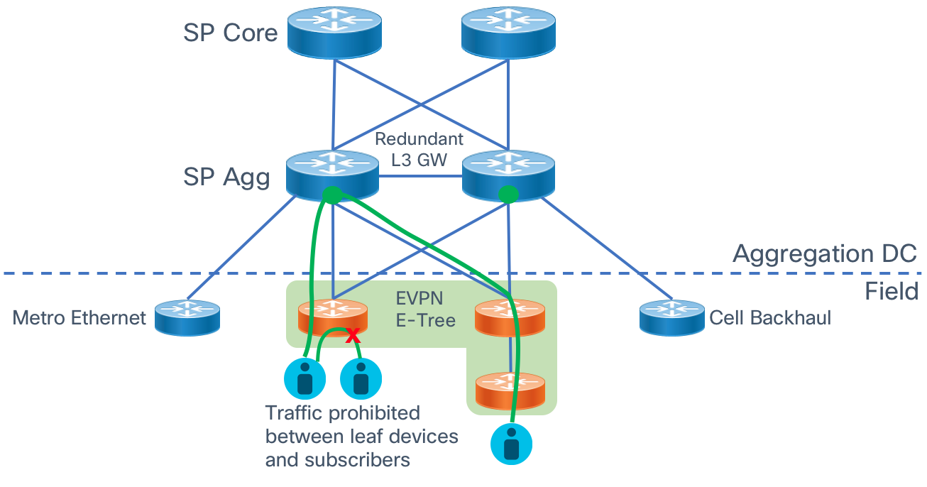
Many providers today are migrating from L2 access networks to more flexible L3 underlay networks using xVPN overlays to support a variety of network services. L3 networks offer more flexibility in terms of topology, resiliency, and support of both L2VPN and L3VPN services. Using a converged aggregation and access network simplifies networks and reduced both capex and opex spend by eliminating duplicate networks. Fiber to the home networks using active Ethernet have typically used L2 designs using proprietary methods like Private VLANs for subscriber isolation. EVPN E-Tree gives us a modern alternative to provide these services across a converged L3 Segment Routing network.
E-Tree Diagram
E-Tree Operation
One of the strongest features of EVPN is its dynamic signaling of PE state across the entire EVPN virtual instance. E-Tree extends this paradigm by signaling between EVPN PEs which Ethernet Segments are considered root segments and which ones are considered leaf segments. Similar to hub and spoke L3VPN networks, traffic is allowed between root/leaf and root/root interfaces but not between leaf interfaces either on the same node or on different nodes. EVPN signaling creates the forwarding state and entries to restrict traffic forwarding between endpoints connected to the same leaf Ethernet Segment.
Split-Horizon Groups
E-Tree enables split horizon groups on access interfaces within the same Bridge Domain/EVI configured for E-Tree to prohibit direct L2 forwarding between these interfaces.
L3 IRB Support
In a fully distributed FTTH deployment, a provider may choose to put the L3 gateway for downstream access endpoints on the leaf device. The L3 BVI interface defined for the E-Tree BD/EVI is always considered a root endpoint. E-Tree operates at L2 so when a L3 interface is present traffic will be forwarded at L3 between leaf endpoints. Note L2 leaf devices using a centralized IRB L3 GW on an E-Tree root node is not currently supported. In this type of deployment where the L3 GW is not located on the leaf the upstream L3 GW node must be attached via a L2 interface into the E-Tree root node Bridge Domani/EVI. It is recommended to locate the L3 GW on the leaf device if possible.
Multicast Traffic
Multicast traffic across the E-Tree L2/L3 network is performed using ingress replication from the source to the receiver nodes. It is important to use IGMP or MLDv2 snooping in order to minimize the flooding of multicast traffic across the entire Ethernet VPN instance. When snooping is utilized, traffic is only sent to EVPN PE nodes with interested receivers instead of all PEs in the EVI.
Ease of Configuration
Configuring a node as a leaf in an E-Tree EVI requires only a single command “etree” to be configured under the EVI in the global EVPN configuration. Please see the Implementation Guide for specific configuration examples.
l2vpn
 bridge group etree
  bridge-domain etree-ftth
  interface TenGigE0/0/0/23.1098
  routed interface BVI100
  !
  evi 100
 !
!
evpn
  evi 100
   etree
   leaf
   !
  advertise-mac
  !
 !
Cable Converged Interconnect Network (CIN)
Summary
The Converged SDN Transport Design enables a multi-service CIN by adding support for the features and functions required to build a scalable next-generation Ethernet/IP cable access network. Differentiated from simple switch or L3 aggregation designs is the ability to support NG cable transport over the same common infrastructure already supporting other services like mobile backhaul and business VPN services. Cable Remote PHY is simply another service overlayed onto the existing Converged SDN Transport network architecture. We will cover all aspects of connectivity between the Cisco cBR-8 and the RPD device.
Distributed Access Architecture
The cable Converged Interconnect Network is part of a next-generation Distributed Access Architecture (DAA), an architecture unlocking higher subscriber bandwidth by moving traditional cable functions deeper into the network closer to end users. R-PHY or Remote PHY, places the analog to digital conversion much closer to users, reducing the cable distance and thus enabling denser and higher order modulation used to achieve Gbps speeds over existing cable infrastructure. This reference design will cover the CIN design to support Remote PHY deployments.
Remote PHY Components and Requirements
This section will list some of the components of an R-PHY network and the network requirements driven by those components. It is not considered to be an exhaustive list of all R-PHY components, please see the CableLabs specification document, the latest which can be access via the following URL: https://specification-search.cablelabs.com/CM-SP-R-PHY
Remote PHY Device (RPD)
The RPD unlocks the benefits of DAA by integrating the physical analog to digital conversions in a device deployed either in the field or located in a shelf in a facility. The uplink side of the RPD or RPHY shelf is simply IP/Ethernet, allowing transport across widely deployed IP infrastructure. The RPD-enabled node puts the PHY function much closer to an end user, allowing higher end-user speeds. The shelf allows cable operators to terminate only the PHY function in a hub and place the CMTS/MAC function in a more centralized facility, driving efficiency in the hub and overall network. The following diagram shows various options for how RPDs or an RPD shelf can be deployed. Since the PHY function is split from the MAC it allows independent placement of those functions.
RPD Network Connections
Each RPD is typically deployed with a single 10GE uplink connection. The compact RPD shelf uses a single 10GE uplink for each RPD.
Cisco cBR-8 and cnBR
The Cisco Converged Broadband Router performs many functions as part of a Remote PHY solution. The cBR-8 provisions RPDs, originates L2TPv3 tunnels to RPDs, provisions cable modems, performs cable subscriber aggregation functions, and acts as the uplink L3 router to the rest of the service provider network. In the Remote PHY architecture the cBR-8 acts as the DOCSIS core and can also serve as a GCP server and video core. The cBR-8 runs IOS-XE. The cnBR, cloud native Broadband Router, provides DOCSIS core functionality in a server-based software platform deployable anywhere in the SP network. CST 3.0 has been validated using the cBR-8, the cnBR will be validated in an upcoming release.
cBR-8 Network Connections
The cBR-8 is best represented as having “upstream” and “downstream” connectivity.
The upstream connections are from the cBR8 Supervisor module to the SP network. Subscriber data traffic and video ingress these uplink connections for delivery to the cable access network. The cBR-8 SUP-160 has 8x10GE SFP+ physical connections, the SUP-250 has 2xQSFP28/QSFP+ interfaces for 40G/100G upstream connections.
In a remote PHY deployment the downstream connections to the CIN are via the Digital PIC (DPIC-8X10G) providing 40G of R-PHY throughput with 8 SFP+ network interfaces.
cBR-8 Redundancy
The cBR-8 supports both upstream and downstream redundancy. Supervisor redundancy uses active/standby connections to the SP network. Downstream redundancy can be configured at both the line card and port level. Line card redundancy uses an active/active mechanism where each RPD connects to the DOCSIS core function on both the active and hot standby Digital PIC line card. Port redundancy uses the concept of “port pairs” on each Digital PIC, with ports 0/1, 2/3, 4/6, and 6/7 using either an active/active (L2) or active/standby (L3) mechanism. In the CST design we utilize a L3 design with the active/standby mechanism. The mechanism uses the same IP address on both ports, with the standby port kept in a physical down state until switchover occurs.
Remote PHY Communication
DHCP
The RPD is provisioned using ZTP (Zero Touch Provisioning). DHCPv4 and DHCPv6 are used along with CableLabs DHCP options in order to attach the RPD to the correct GCP server for further provisioning.
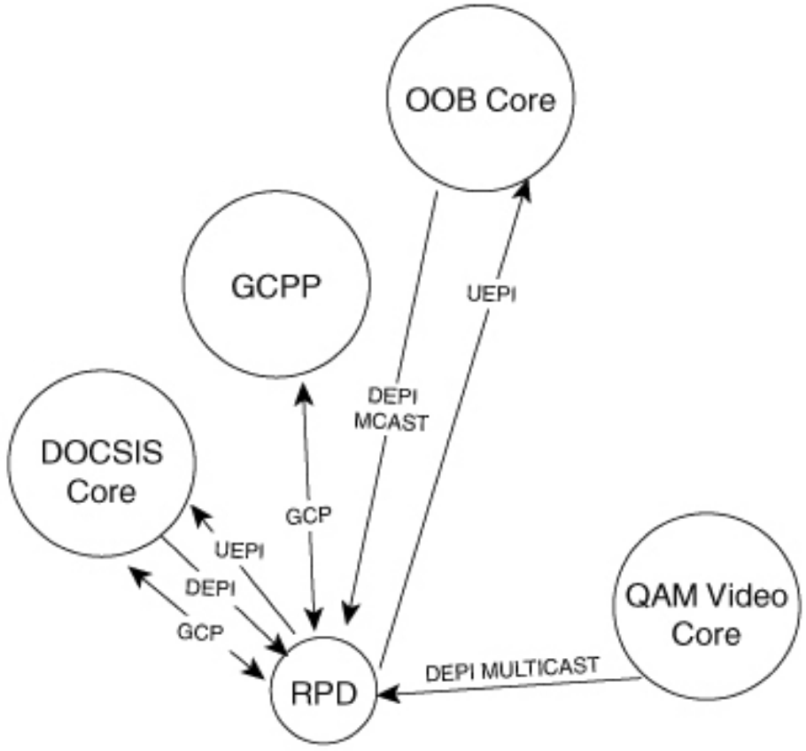
Remote PHY Standard Flows
The following diagram shows the different core functions of a Remote PHY solution and the communication between those elements.
GCP
Generic Communications Protocol is used for the initial provisioning of the RPD. When the RPD boots and received its configuration via DHCP, one of the DHCP options will direct the RPD to a GCP server which can be the cBR-8 or Cisco Smart PHY. GCP runs over TCP typically on port 8190.
UEPI and DEPI L2TPv3 Tunnels
The upstream output from an RPD is IP/Ethernet, enabling the simplification of the cable access network. Tunnels are used between the RPD PHY functions and DOCSIS core components to transport signals from the RPD to the core elements, whether it be a hardware device like the Cisco cBR-8 or a virtual network function provided by the Cisco cnBR (cloud native Broadband Router).
DEPI (Downstream External PHY Interface) comes from the M-CMTS architecture, where a distributed architecture was used to scale CMTS functions. In the Remote PHY architecture DEPI represents a tunnel used to encapsulate and transport from the DOCSIS MAC function to the RPD. UEPI (Upstream External PHY Interface) is new to Remote PHY, and is used to encode and transport analog signals from the RPD to the MAC function.
In Remote PHY both DEPI and UEPI tunnels use L2TPv3, defined in RFC 3931, to transport frames over an IP infrastructure. Please see the following Cisco white paper for more information on how tunnels are created specific to upstream/downstream channels and how data is encoded in the specific tunnel sessions. https://www.cisco.com/c/en/us/solutions/collateral/service-provider/converged-cable-access-platform-ccap-solution/white-paper-c11-732260.html. In general there will be one or two (standby configuration) UEPI and DEPI L2TPv3 tunnels to each RPD, with each tunnel having many L2TPv3 sessions for individual RF channels identified by a unique session ID in the L2TPv3 header. Since L2TPv3 is its own protocol, no port number is used between endpoints, the endpoint IP addresses are used to identify each tunnel. Unicast DOCSIS data traffic can utilize either or multicast L2TPv3 tunnels. Multicast tunnels are used with downstream virtual splitting configurations. Multicast video is encoded and delivered using DEPI tunnels as well, using a multipoint L2TPv3 tunnel to multiple RPDs to optimize video delivery.
CIN Network Requirements
IPv4/IPv6 Unicast and Multicast
Due to the large number of elements and generally greenfield network builds, the CIN network must support all functions using both IPv4 and IPv6. IPv6 may be carried natively across the network or within an IPv6 VPN across an IPv4 MPLS underlay network. Similarly the network must support multicast traffic delivery for both IPv4 and IPv6 delivered via the global routing table or Multicast VPN. Scalable dynamic multicast requires the use of PIMv4, PIMv6, IGMPv3, and MLDv2 so these protocols are validated as part of the overall network design. IGMPv2 and MLDv2 snooping are also required for designs using access bridge domains and BVI interfaces for aggregation.
Network Timing
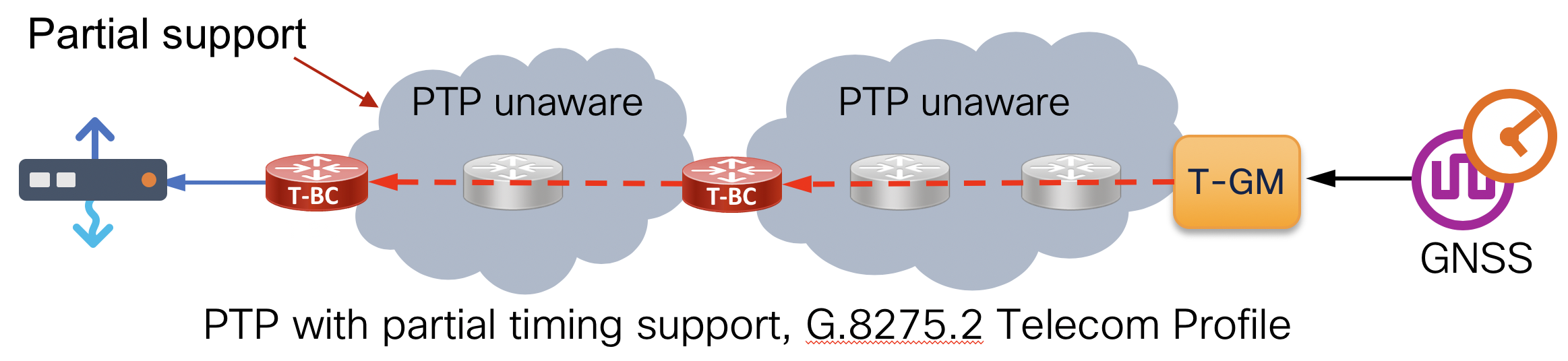
Frequency and phase synchronization is required between the cBR-8 and RPD to properly handle upstream scheduling and downstream transmission. Remote PHY uses PTP (Precision Timing Protocol) for timing synchronization with the ITU-T G.8275.2 timing profile. This profile carries PTP traffic over IP/UDP and supports a network with partial timing support, meaning multi-hop sessions between Grandmaster, Boundary Clocks, and clients as shown in the diagram below. The cBR-8 and its client RPD require timing alignment to the same Primary Reference Clock (PRC). In order to scale, the network itself must support PTP G.8275.2 as a T-BC (Boundary Clock). Synchronous Ethernet (SyncE) is also recommended across the CIN network to maintain stability when timing to the PRC.
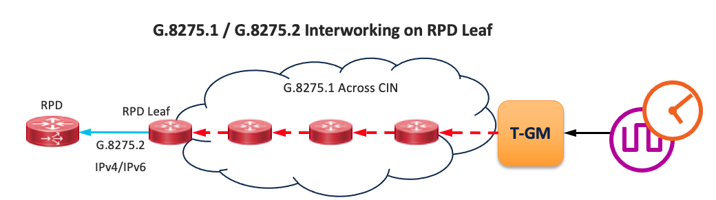
CST 4.0+ Update to CIN Timing Design
Starting in CST 4.0, NCS nodes support both G.8275.1 and G.8275.2 on the same node, and also support interworking between them. If the network path between the PTP GM and client RPDs can support G.8275.1 on each hop, it should be used. G.8275.1 runs on physical interfaces and does not have limitations such as running over Bundle Ethernet interfaces. The G.8275.1 to G.8275.2 interworking will take place on the RPD leaf node, with G.8275.2 being used to the RPDs. The following diagram depicts a recommended end-to-end timing design between the PTP GM and the RPD. Please review the CST 4.0 Implementation Guide for details on configuring G.8275.1 to G.8275.2 interworking. In addition to PTP interworking, CST 4.0 supports PTP timing on BVI interfaces.
QoS
Control plane functions of Remote PHY are critical to achieving proper operation and subscriber traffic throughput. QoS is required on all RPD-facing ports, the cBR-8 DPIC ports, and all core interfaces in between. Additional QoS may be necessary between the cBR-8, RPD, and any PTP timing elements. See the design section for further details on QoS components.
DHCPv4 and DHCPv6 Relay
As a critical component of the initial boot and provisioning of RPDs, the network must support DHCP relay functionality on all RPD-facing interfaces, for both IPv4 and IPv6.
Converged SDN Transport CIN Design
Deployment Topology Options
The Converged SDN Transport design is extremely flexible in how Remote PHY components are deployed. Depending on the size of the deployment, components can be deployed in a scalable leaf-spine fabric with dedicated routers for RPD and cBR-8 DPIC connections or collapsed into a single pair of routers for smaller deployments. If a smaller deployment needs to be expanded, the flexible L3 routed design makes it very easy to simply interconnect new devices and scale the design to a fabric supporting thousands of RPD and other access network connections.
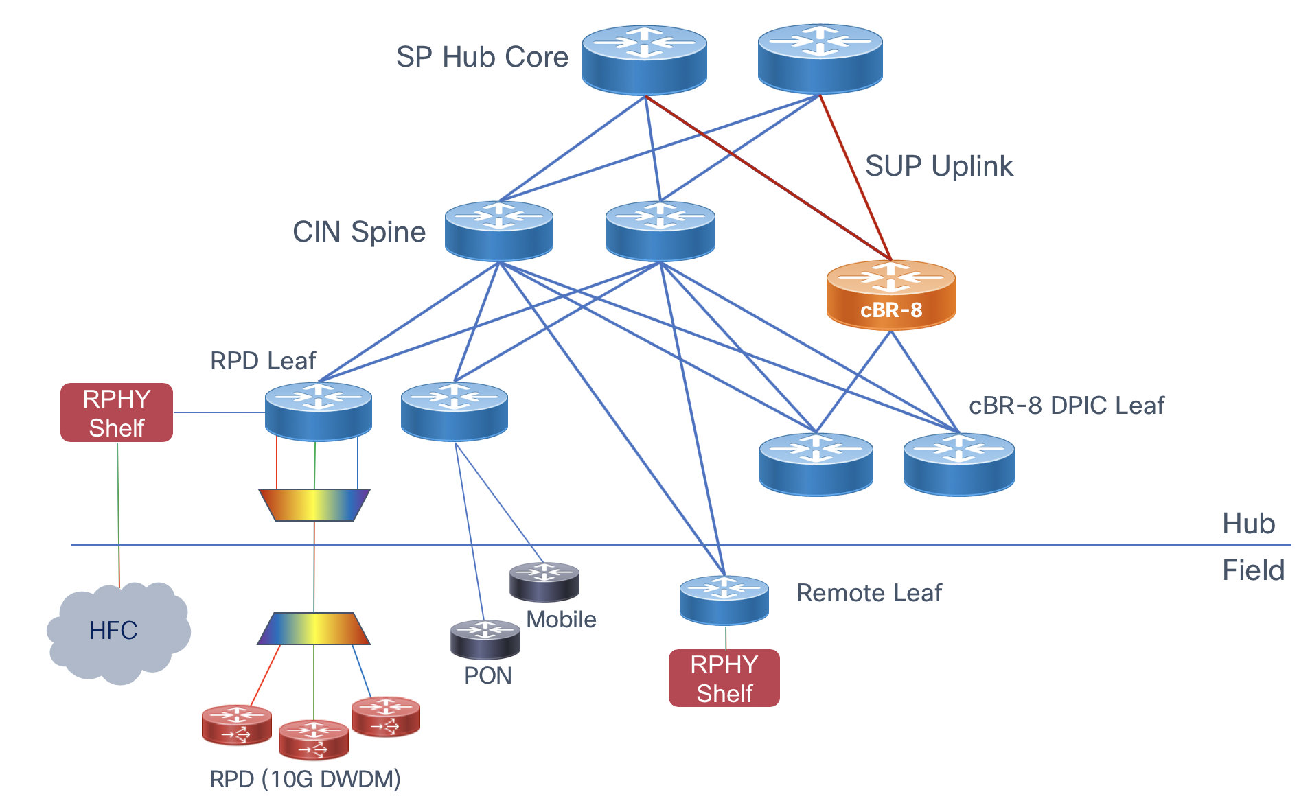
High Scale Design (Recommended)
This option maximizes statistical multiplexing by aggregating Digital PIC downstream connections on a separate leaf device, allowing one to connect a number of cBR-8 interfaces to a fabric with minimal 100GE uplink capacity. The topology also supports the connectivity of remote shelves for hub consolidation. Another benefit is the fabric has optimal HA and the ability to easily scale with more leaf and spine nodes.
 High scale topology
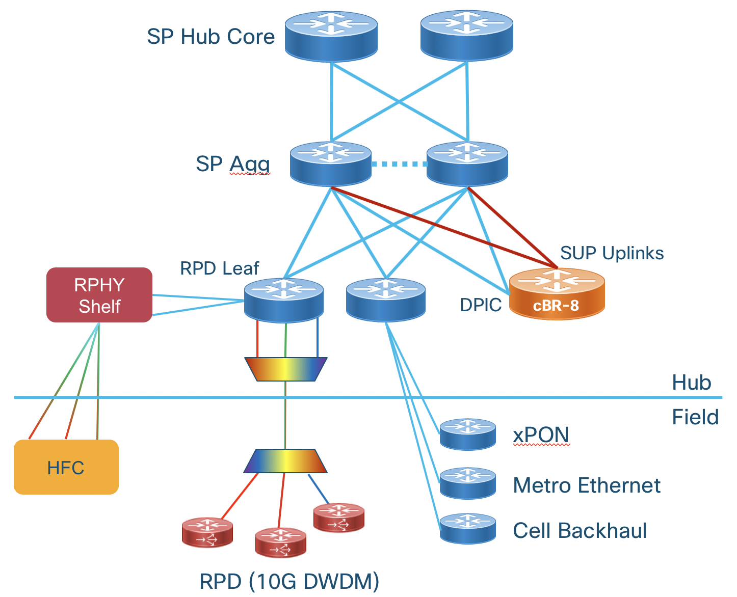
Collapsed Digital PIC and SUP Uplink Connectivity
This design for smaller deployments connects both the downstream Digital PIC connections and uplinks on the same CIN core device. If there is enough physical port availability and future growth does not dictate capacity beyond these nodes this design can be used. This design still provides full redundancy and the ability to connect RPDs to any cBR-8. Care should be taken to ensure traffic between the DPIC and RPD does not traverse the SUP uplink interfaces.
 Collapsed cBR-8 uplink and Digital PIC connectivity
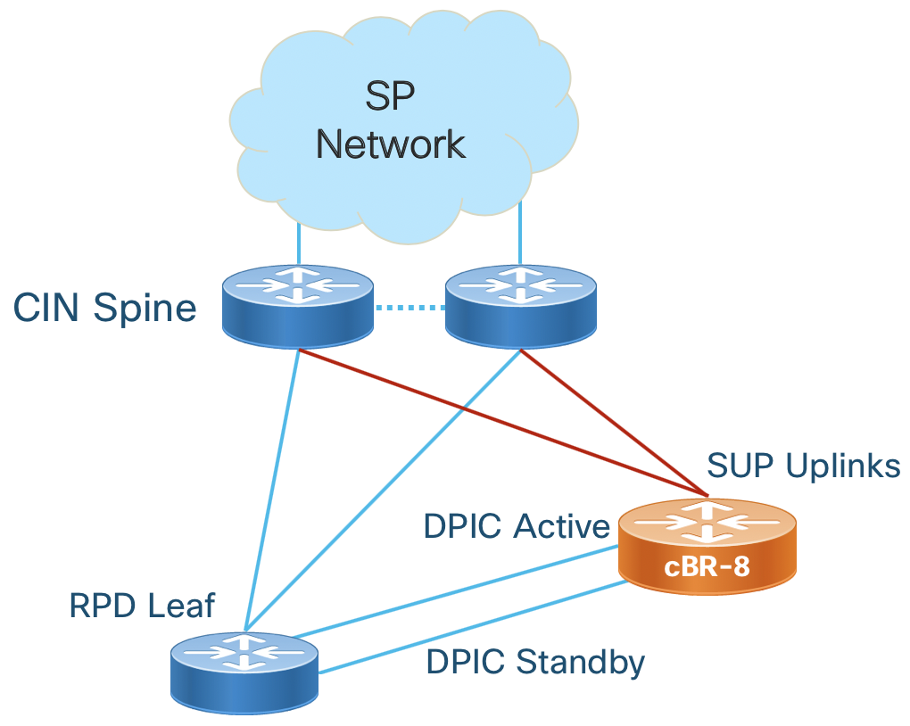
Collapsed RPD and cBR-8 DPIC Connectivity
This design connects each cBR-8 Digital PIC connection to the RPD leaf connected to the RPDs it will serve. This design can also be considered a “pod” design where cBR-8 and RPD connectivity is pre-planned. Careful planning is needed since the number of ports on a single device may not scale efficiently with bandwidth in this configuration.
 Collapsed or Pod cBR-8 Digital PIC and RPD connectivity
In the collapsed desigs care must be taken to ensure traffic between each RPD can reach the appropriate DPIC interface. If a leaf is single-homed to the aggregation router its DPIC interface is on, RPDs may not be able to reach their DPIC IP. The options with the shortest convergence time are: Adding interconnects between the agg devices or multiple uplinks from the leaf to agg devices.
Cisco Hardware
The following table highlights the Cisco hardware utilized within the Converged SDN Transport design for Remote PHY. This table is non-exhaustive. One highlight is all NCS platforms listed are built using the same NPU family and share most features across all platforms. See specific platforms for supported scale and feature support.
| Product | Role | 10GE SFP+ | 25G SFP28 | 100G QSFP28 | Timing | Comments |
|---|---|---|---|---|---|---|
| NCS-55A1-24Q6H-S | RPD leaf | 48 | 24 | 6 | Class B | |
| N540-ACC-SYS | RPD leaf | 24 | 8 | 2 | Class B | Smaller deployments |
| NCS-55A1-48Q6H-S | DPIC leaf | 48 | 48 | 6 | Class B | |
| NCS-55A2-MOD | Remote agg | 40 | 24 | upto 8 | Class B | CFP2-DCO support |
| NCS-55A1-36H-S | Spine | 144 (breakout) | 0 | 36 | Class B | |
| NCS-5502 | Spine | 192 (breakout) | 0 | 48 | None | |
| NCS-5504 | Multi | Upto 576 | x | Upto 144 | Class B | 4-slot modular platform |
Scalable L3 Routed Design
The Cisco validated design for cable CIN utilizes a L3 design with or without Segment Routing. Pure L2 networks are no longer used for most networks due to their inability to scale, troubleshooting difficulty, poor network efficiency, and poor resiliency. L2 bridging can be utilized on RPD aggregation routers to simplify RPD connectivity.
L3 IP Routing
Like the overall CST design, we utilize IS-IS for IPv4 and IPv6 underlay routing and BGP to carry endpoint information across the network. The following diagram illustrates routing between network elements using a reference deployment. The table below describes the routing between different functions and interfaces. See the implementation guide for specific configuration.
| Interface | Routing | Comments |
|---|---|---|
| cBR-8 Uplink | IS-IS | Used for BGP next-hop reachability to SP Core |
| cBR-8 Uplink | BGP | Advertise subscriber and cable-modem routes to SP Core |
| cBR-8 DPIC | Static default in VRF | Each DPIC interface should be in its own VRF on the cBR-8 so it has a single routing path to its connected RPDs |
| RPD Leaf Main | IS-IS | Used for BGP next-hop reachability |
| RPD Leaf Main | BGP | Advertise RPD L3 interfaces to CIN for cBR-8 to RPD connectivity |
| RPD Leaf Timing | BGP | Advertise RPD upstream timing interface IP to rest of network |
| DPIC Leaf | IS-IS | Used for BGP next-hop reachability |
| DPIC Leaf | BGP | Advertise cBR-8 DPIC L3 interfaces to CIN for cBR-8 to RPD connectivity |
| CIN Spine | IS-IS | Used for reachability between BGP endpoints, the CIN Spine does not participate in BGP in a SR-enabled network |
| CIN Spine RPD Timing | IS-IS | Used to advertise RPD timing interface BGP next-hop information and advertise default |
| CIN Spine | BGP (optional) | In a native IP design the spine must learn BGP routes for proper forwarding |
CIN Router to Router Interconnection
It is recommended to use multiple L3 links when interconnecting adjacent routers, as opposed to using LAG, if possible. Bundles increase the possibility for timing inaccuracy due to asymmetric timing traffic flow between slave and master. If bundle interfaces are utilized, care should be taken to ensure the difference in paths between two member links is kept to a minimum. All router links will be configured according to the global CST design. Leaf devices will be considered CST access PE devices and utilize BGP for all services routing.
Leaf Transit Traffic
In a single IGP network with equal IGP metrics, certain link failures may cause a leaf to become a transit node. Several options are available to keep transit traffic from transiting a leaf and potentially causing congestion. Using high metrics on all leaf to agg uplinks will prohibit this and is recommended in all configurations.
cBR-8 DPIC to CIN Interconnection
The cBR-8 supports two mechanisms for DPIC high availability outlined in the overview section. DPIC line card and link redundancy is recommended but not a requirement. In the CST reference design, if link redundancy is being used each port pair on the active and standby line cards is connected to a different router and the default active ports (even port number) is connected to a different router. In the example figure, port 0 from active DPIC card 0 is connected to R1 and port 0 from standby DPIC card 1 is connected to R2. DPIC link redundancy MUST be configured using the “cold” method since the design is using L3 to each DPIC interface and no intermediate L2 switching. This is done with the cable rphy link redundancy cold global command and will keep the standby link in a down/down state until switchover occurs.
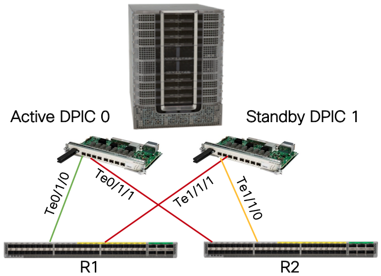 DPIC line card and link HA
DPIC Interface Configuration
Each DPIC interface should be configured in its own L3 VRF. This ensures traffic from an RPD assigned to a specific DPIC interface takes the traffic path via the specific interface and does not traverse the SUP interface for either ingress or egress traffic. It’s recommended to use a static default route within each DPIC VRF towards the CIN network. Dynamic routing protocols could be utilized, however it will slow convergence during redundancy switchover.
Router Interface Configuration
If no link redundancy is utilized each DPIC interface will connect to the router using a point to point L3 interface.
If using cBR-8 link HA, failover time is reduced by utilizing the same gateway MAC address on each router. Link HA uses the same IP and MAC address on each port pair on the cBR-8, and retains routing and ARP information for the L3 gateway. If a different MAC address is used on each router, traffic will be dropped until an ARP occurs to populate the GW MAC address on the router after failover. On the NCS platforms, a static MAC address cannot be set on a physical L3 interface. The method used to set a static MAC address is to use a BVI (Bridged Virtual Interface), which allows one to set a static MAC address. In the case of DPIC interface connectivity, each DPIC interface should be placed into its own bridge domain with an associated BVI interface. Since each DPIC port is directly connected to the router interface, the same MAC address can be utilized on each BVI.
If using IS-IS to distribute routes across the CIN, each DPIC physical interface or BVI should be configured as a passive IS-IS interface in the topology. If using BGP to distribute routing information the “redistribute connected” command should be used with an appropriate route policy to restrict connected routes to only DPIC interface. The BGP configuration is the same whether using L3VPN or the global routing table.
It is recommended to use a /31 for IPv4 and /127 for IPv6 addresses for each DPIC port whether using a L3 physical interface or BVI on the CIN router.
RPD to Router Interconnection
The Converged SDN Transport design supports both P2P L3 interfaces for RPD and DPIC aggregation as well as using Bridge Virtual Interfaces. A BVI is a logical L3 interface within a L2 bridge domain. In the BVI deployment the DPIC and RPD physical interfaces connected to a single leaf device share a common IP subnet with the gateway residing on the leaf router.
It is recommended to configure the RPD leaf using bridge-domains and BVI interfaces. This eases configuration on the leaf device as well as the DHCP configuration used for RPD provisioning.
The following shows the P2P and BVI deployment options.
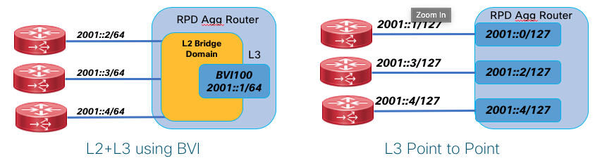
Native IP or L3VPN/mVPN Deployment
Two options are available and validated to carry Remote PHY traffic between the RPD and MAC function.
Native IP means the end to end communication occurs as part of the global routing table. In a network with SR-MPLS deployed such as the CST design, unicast IP traffic is still carried across the network using an MPLS header. This allows for fast reconvergence in the network by using SR and enabled the network to carry other VPN services on the network even if they are not used to carry Remote PHY traffic. In then native IP deployment, multicast traffic uses either PIM signaling with IP multicast forwarding or mLDP in-band signaling for label-switched multicast. The multicast profile used is profile 7 (Global mLDP in-band signaling).
L3VPN and mVPN can also be utilized to carry Remote PHY traffic within a VPN service end to end. This has the benefit of separating Remote PHY traffic from the network underlay, improving security and treating Remote PHY as another service on a converged access network. Multicast traffic in this use case uses mVPN profile 14. mLDP is used for label-switched multicast, and the NG-MVPN BGP control plane is used for all multicast discovery and signaling.
SR-TE
Segment Routing Traffic Engineering may be utilized to carry traffic end to end across the CIN network. Using On-Demand Networking simplifies the deployment of SR-TE Policies from ingress to egress by using specific color BGP communities to instruct head-end nodes to create policies satisfying specific user constraints. As an example, if RPD aggregation prefixes are advertised using BGP to the DPIC aggregation device, SR-TE tunnels following a user constraint can be built dynamically between those endpoints.
CIN Quality of Service (QoS)
QoS is a requirement for delivering trouble-free Remote PHY. This design uses sample QoS configurations for concept illustration, but QoS should be tailored for specific network deployments. New CIN builds can utilize the configurations in the implementation guide verbatim if no other services are being carried across the network. Please see the section in this document on QoS for general NCS QoS information and the implementation guide for specific details.
CST Network Traffic Classification
The following lists specific traffic types which should be treated with specific priority, default markings, and network classification points.
| Traffic Type | Ingress Interface | Priority | Default Marking | Comments |
|---|---|---|---|---|
| BGP | Routers, cBR-8 | Highest | CS6 (DSCP 48) | None |
| IS-IS | Routers, cBR-8 | Highest | CS6 | IS-IS is single-hop and uses highest priority queue by default |
| BFD | Routers | Highest | CS6 | BFD is single-hop and uses highest priority queue by default |
| DHCP | RPD | High | CS5 | DHCP COS is set explicitly |
| PTP | All | High | DSCP 46 | Default on all routers, cBR-8, and RPD |
| DOCSIS MAP/UCD | RPD, cBR-8 DPIC | High | DSCP 46 | |
| DOCSIS BWR | RPD, cBR-8 DPIC | High | DSCP 46 | |
| GCP | RPD, cBR-8 DPIC | Low | DSCP 0 | |
| DOCSIS Data | RPD, cBR-8 DPIC | Low | DSCP 0 | |
| Video | cBR-8 | Medium | DSCP 32 | Video within multicast L2TPv3 tunnel when cBR-8 is video core |
| MDD | RPD, cBR-8 | Medium | DSCP 40 |
CST and Remote-PHY Load Balancing
Unicast network traffic is load balanced based on MPLS labels and IP header criteria. The devices used in the CST design are capable of load balancing traffic based on MPLS labels used in the SR underlay and IP headers underneath any MPLS labels. In the higher bandwidth downstream direction, where a series of L2TP3 tunnels are created from the cBR-8 to the RPD, traffic is hashed based on the source and destination IP addresses of those tunnels. Downstream L2TPv3 tunnels from a single Digital PIC interface to a set of RPDs will be distributed across the fabric based on RPD destination IP address. The followUing illustrates unicast load balancing across the network.

Multicast traffic is not load balanced across the network. Whether the network is utilizing PIMv4, PIMv6, or mVPN, a multicast flow with two equal cost downstream paths will utilize only a single path, and only a single member link will be utilized in a link bundle. If using multicast, ensure sufficient bandwidth is available on a single link between two adjacencies.
SmartPHY RPD Automation
SmartPHY is an automation solution for managing deployed RPDs across the SP network. In a non-SmartPHY deployment providers must manually assign RPHY cores via DHCP and manually configure the cBR8 by CLI SmartPHY provides a flexible either GUI or API driven way to eliminate manual configuration. SmartPHY is configured as the RPHY core in the DHCP server for all RPDs. When the RPD boots it will initiate a GCP session to SmartPHY. SmartPHY identifies the RPD and if configured in SmartPHY, will redirect it to the proper RPHY core instance. When provisioning a new RPD, SmartPHY will also deploy the proper configuration to the RPHY core cBR8 node and verify the RPD is operational. The diagram below shows basic SmartPHY operation.
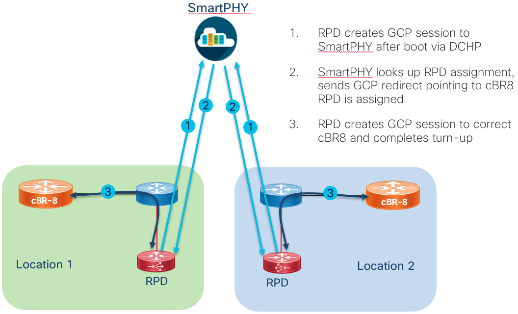
4G Transport and Services Modernization
While talk about deploying 5G services has reached a fever pitch, many providers are continuing to build and evolve their 4G networks. New services require more agile and scalable networks, satisfied by Cisco’s Converged SDN Transport. The services modernization found in Converged SDN Transport 2.0 follows work done in EPN 4.0 located here: https://www.cisco.com/c/dam/en/us/td/docs/solutions/Enterprise/Mobility/EPN/4_0/EPN_4_Transport_Infrastructure_DIG.pdf. Transport modernization requires simplification and new abilities. We evolve the EPN 4.0 design based on LDP and hierarchical BGP-LU to one using Segment Routing with an MPLS data plane and the SR-PCE to add inter-domain path computation, scale, and programmability. L3VPN based 4G services remain, but are modernized to utilize SR-TE On-Demand Next-Hop, reducing provisioning complexity, increasing scale, and adding advanced path computation constraints. 4G services utilizing L3VPN remain the same, but those utilizing L2VPN such as VPWS and VPLS transition to EVPN services. EVPN is the modern replacement for legacy LDP signalled L2VPN services, reducing complexity and adding advanced multi-homing functionality. The following table highlights the legacy and new way of delivering services for 4G.
| Element | EPN 4.0 | Converged SDN Transport |
|---|---|---|
| Intra-domain MPLS Transport | LDP | IS-IS w/Segment Routing |
| Inter-domain MPLS Transport | BGP Labeled Unicast | SR using SR-PCE for Computation |
| MPLS L3VPN (LTE S1,X2) | MPLS L3VPN | MPLS L3VPN w/ODN |
| L2VPN VPWS | LDP Pseudowire | EVPN VPWS w/ODN |
| eMBMS Multicast | Native / mLDP | Native / mLDP |
The CST 4G Transport modernization covers only MPLS-based access and not L2 access scenarios.
L3 IP Multicast and mVPN
IP multicast continues to be an optimization method for delivering content traffic to many endpoints, especially traditional broadcast video. Unicast content dominates the traffic patterns of most networks today, but multicast carries critical high value services, so proper design and implementation is required. In Converged SDN Transport 2.0 we introduced multicast edge and core validation for native IPv4/IPv6 multicast using PIM, global multicast using in-band mLDP (profile 7), and mVPN using mLDP with in-band signaling (profile 6). Converged SDN Transport 3.0 extends this functionality by adding support for mLDP LSM with the NG-MVPN BGP control plane (profile 14). Using BGP signaling adds additional scale to the network over in-band mLDP signaling and fits with the overall design goals of CST. More information about deployment of profile 14 can be found in the Converged SDN Transport implementation guide. Converged SDN Transport 3.0 supports mLDP-based label switched multicast within a single doman and across IGP domain boundaries. In the case of the Converged SDN Transport design multicast has been tested with the source and receivers on both access and ABR PE devices.
| Supported Multicast Profiles | Description |
|---|---|
| Profile 6 | mLDP VRF using in-band signaling |
| Profile 7 | mLDP global routing table using in-band signaling |
| Profile 14 | Partitioned MDT using BGP-AD and BGP c-multicast signaling |
LDP Auto-configuration
LDP can automatically be enabled on all IS-IS interfaces with the following configuration in the IS-IS configuration
router isis ACCESS
 address-family ipv4 unicast
  mpls ldp auto-config
LDP mLDP-only Session Capability (RFC 7473)
In Converged SDN Transport 3.0 we introduce the ability to only advertise mLDP state on each router adjacency, eliminating the need to filter LDP unicast FECs from advertisement into the network. This is done using the SAC (State Advertisement Control) TLV in the LDP initialization messages to advertise which LDP FEC classes to receive from an adjacent peer. We can restrict the capabilities to mLDP only using the following configuration. Please see the implementation guide and configurations for the full LDP configuration.
mpls ldp
 capabilities sac mldp-only
LDP Unicast FEC Filtering for SR Unicast with mLDP Multicast
The following is for historical context, please see the above section regarding disabling LDP unicast FECs using session capability advertisements.
The Converged SDN Transport design utilized Segment Routing with the MPLS dataplane for all unicast traffic. The first phase of multicast support in Converged SDN Transport 2.0 will use mLDP for use with existing mLDP based networks and new networks wishing to utilize label switcched multicast across the core. LDP is enabled on an interface for both unicast and multicast by default. Since SR is being used for unicast, one must filtering out all LDP unicast FECs to ensure they are not distributed across the network. SR is used for all unicast traffic in the presence of an LDP FEC for the same prefix, but filtering them reduces control-plane activity, may aid in re-convergence, and simplifies troubleshooting. The following should be applied to all interfaces which have mLDP enabled:
ipv4 access-list no-unicast-ldp
10 deny ipv4 any any
!
RP/0/RSP0/CPU0:Node-6#show run mpls ldp
mpls ldp
log
  neighbor
address-family ipv4
  label
   local
    allocate for no-unicast-ldp
L3 Multicast using Segment Routing TreeSID w/Static S,G Mapping
TreeSID Diagram
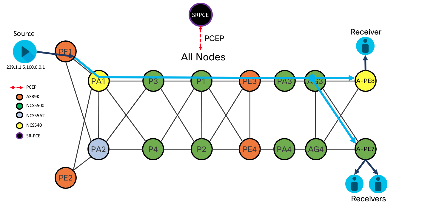
TreeSID Overview
Converged SDN Transport 3.5 introduces Segment Routing Tree SID across all IOS-XR nodes. TreeSID utilizes the programmability of SR-PCE to create and maintain an optimized multicast tree from source to receiver across an SR-only IPv4 network. In CST 3.5 TreeSID utilizes MPLS labels at each hop in the network. Each node in the network maintains a session to the same set of SR-PCE controllers. The SR-PCE creates the tree using PCE-initiated segments. TreeSID supports advanced functionality such as TI-LFA for fast protection and disjoint trees.
Traffic is forwarded across the tree in CST 3.5 using static S,G mappings at the head-end source nodes and tail-end receiver nodes. Providers needing a solution where dynamic joins and leaves are not common, such as broadcast video deployments, can be benefit from the simplicity static TreeSID brings, eliminating the need for distributed BGP mVPN signaling. TreeSID is supported for both default VRF (Global Routing Table) and mVPN.
Please see the CST 3.5 Implementation Guide for TreeSID configuration guidelines and examples.
EVPN Multicast
Multicast within a L2VPN EVPN has been supported since Converged SDN Transport 1.0. Multicast traffic within an EVPN is replicated to the endpoints interested in a specific group via EVPN signaling. EVPN utilizes ingress replication for all multicast traffic, meaning multicast is encapsulated with a specific EVPN label and unicast to each PE router with interested listeners for each multicast group. Ingress replication may add additional traffic to the network, but simplifies the core and data plane by eliminating multicast signaling, state, and hardware replication. EVPN multicast is also not subject to domain boundary restrictions.
LDP to Converged SDN Transport Migration
Very few networks today are built as greenfield networks, most new designs are migrated from existing ones and must support some level of interop during migration. In the Converged SDN Transport design we tackle one of the most common migration scenarios, LDP to the Converged SDN Transport design. The following sections explain the configuration and best practices for performing the migration. The design is applicable to transport and services originating and terminating in the same LDP domain.
Towards Converged SDN Transport Design
The Converged SDN Transport design utilizes isolated IGP domains in different parts of the network, with each domain separated at a logical boundary by an ASBR router. SR-PCE is used to provide end to end paths across the inter-domain network. LDP does not support inter-domain transport, only between LDP FECs in the same IGP domain. It is recommended to plan logical boundaries if necessary when doing a flat LDP migration to the Converged SDN Transport design, so that when migration is complete the future scale benefits can be realized.
Segment Routing Enablement
One must define the global Segment Routing Block (SRGB) to be used across the network on every node participating in SR. There is a default block enabled by default but it may not be large enough to support an entire network, so it’s advised to right-size this value for your deployment. The current maximum SRGB size for SR-MPLS is 256K entries.
Enabling SR in IS-IS requires only issuing the command “segment-routing mpls” under the IPv4 address-family and assigning a prefix-sid value to any loopback interfaces you require the node be addressed towards as a service destination. Enabling TI-LFA is done on a per-interface basis in the IS-IS configuration for each interface.
Enabling SR-Prefer within IS-IS aids in migration by preferring a SR prefix-sid to a prefix over an LDP prefix, allowing a seamless migration to SR without needing to enable SR completely within a domain.
Segment Routing Mapping Server Design
One component introduced with Segment Routing is the SR Mapping Server (SRMS), a control-plane element converting unicast LDP FECs to Segment Routing prefix-SIDs for advertisement throughout the Segment Routing domain. Each separate IGP domain requires a pair of SRMS nodes until full migratino to SR is complete.
Automation
Zero Touch Provisioning
In addition to model-driven configuration and operation, Converged SDN Transport 1.5 supports ZTP operation for automated device provisioning. ZTP is useful both in production as well as staging environments to automate initial device software installation, deploy an initial bootstrap configuration, as well as advanced functionality triggered by ZTP scripts. ZTP is supported on both out of band management interfaces as well as in-band data interfaces. When a device first boots, the IOS-XR ZTP process beging on the management interface of the device and if no response is received, or the the interface is not active, the ZTP process will begin the process on data ports. IOS-XR can be part of an ecosystem of automated device and service provisioning via Cisco NSO.
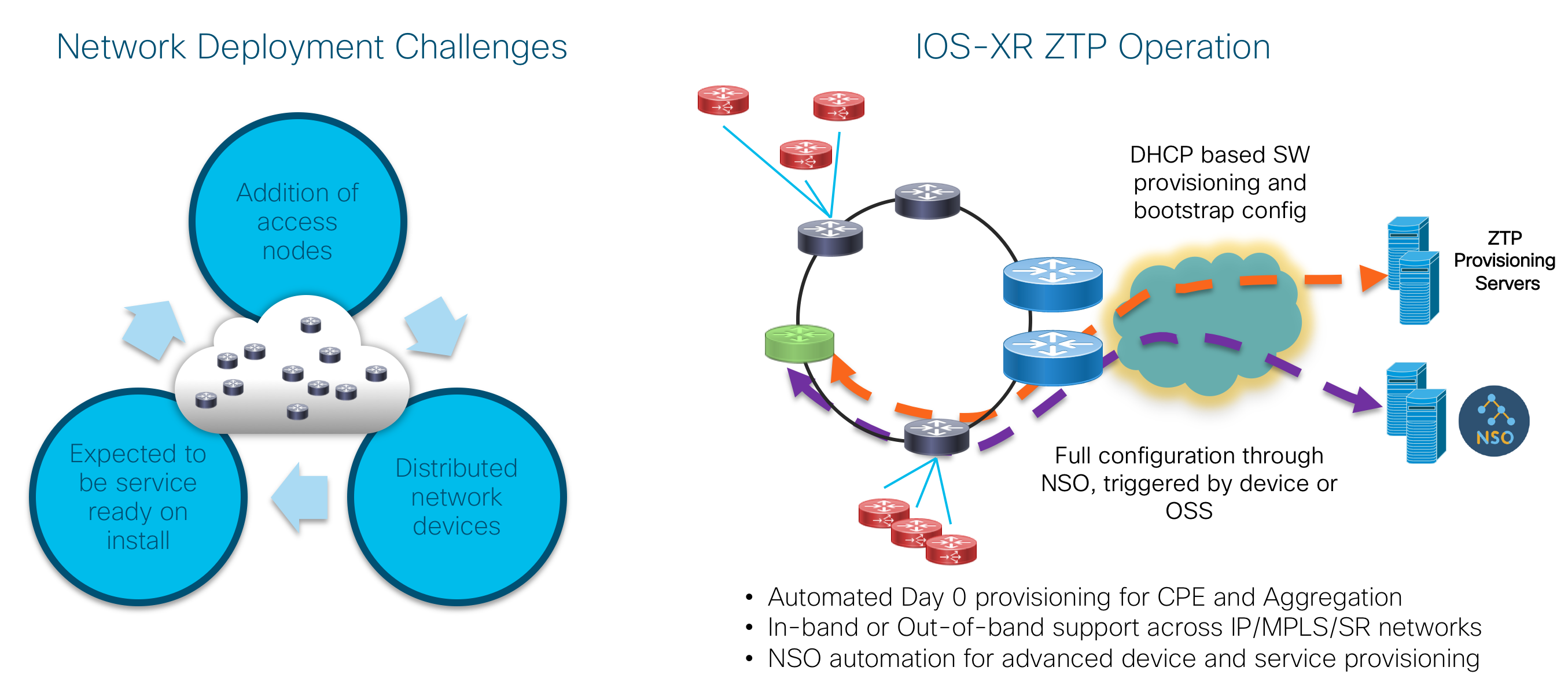
Model-Driven Telemetry
In the 3.0 release the implementation guide includes a table of model-driven telemetry paths applicable to different components within the design. More information on Cisco model-driven telemetry can be found at https://www.cisco.com/c/en/us/td/docs/iosxr/ncs5500/telemetry/66x/b-telemetry-cg-ncs5500-66x.html. Additional information about how to consume and visualize telemetry data can be found at https://xrdocs.io/telemetry. We also introduce integration with Cisco Crosswork Health Insights, a telemetry and automated remediation platform, and sensor packs correspondding to Converged SDN Transport components. More information on Crosswork Health Insights can be found at https://www.cisco.com/c/en/us/support/cloud-systems-management/crosswork-health-insights/model.html.
Network Services Orchestrator (NSO)
The NSO is a management and orchestration (MANO) solution for network services and Network Functions Virtualization (NFV). The NSO includes capabilities for describing, deploying, configuring, and managing network services and VNFs, as well as configuring the multi-vendor physical underlay network elements with the help of standard open APIs such as NETCONF/YANG or a vendor-specific CLI using Network Element Drivers (NED).
In the Converged SDN Transport design, the NSO is used for Services Management, Service Provisioning, and Service Orchestration.
The NSO provides several options for service designing as shown in Figure 32
Service model with service template
Service model with mapping logic
Service model with mapping logic and service templates
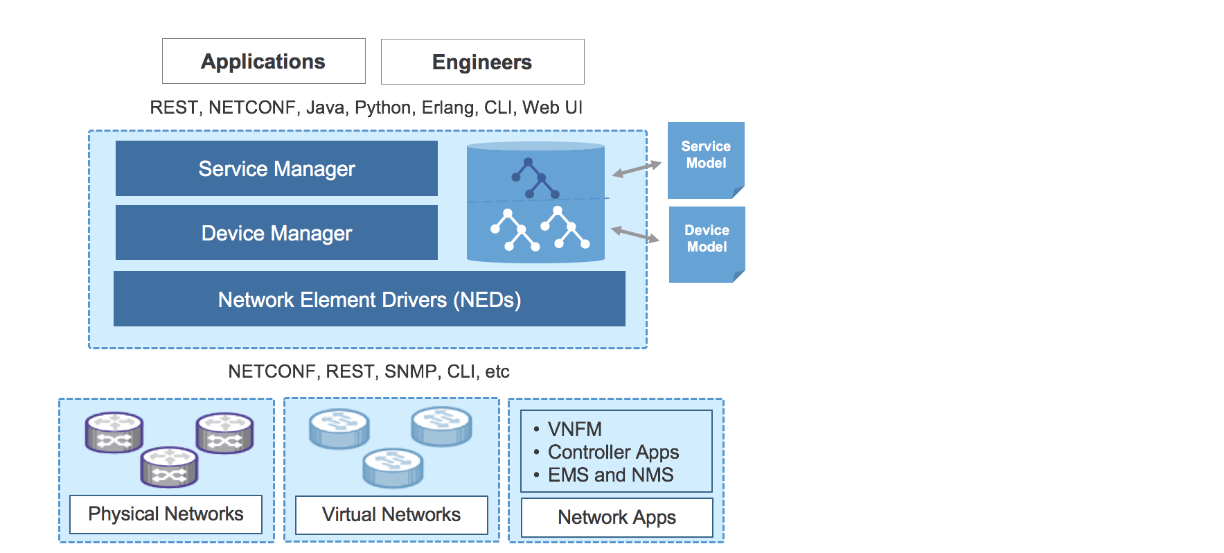
Figure 32: NSO – Components
A service model is a way of defining a service in a template format. Once the service is defined, the service model accepts user inputs for the actual provisioning of the service. For example, a E-Line service requires two endpoints and a unique virtual circuit ID to enable the service. The end devices, attachment circuit UNI interfaces, and a circuit ID are required parameters that should be provided by the user to bring up the E-Line service. The service model uses the YANG modeling language (RFC 6020) inside NSO to define a service.
Once the service characteristics are defined based on the requirements, the next step is to build the mapping logic in NSO to extract the user inputs. The mapping logic can be implemented using Python or Java. The purpose of the mapping logic is to transform the service models to device models. It includes mechanisms of how service related operations are reflected on the actual devices. This involves mapping a service operation to available operations on the devices.
Finally, service templates need to be created in XML for each device type. In NSO, the service templates are required to translate the service logic into final device configuration through CLI NED. The NSO can also directly use the device YANG models using NETCONF for device configuration. These service templates enable NSO to operate in a multi-vendor environment.
Converged SDN Transport Supported Service Models
Converged SDN Transport 1.5 and later supports the following NSO service models for provisioning both hierarchical and flat services across the fabric. All NSO service modules in 1.5 utilize the IOS-XR and IOS-XE CLI NEDs for configuration.
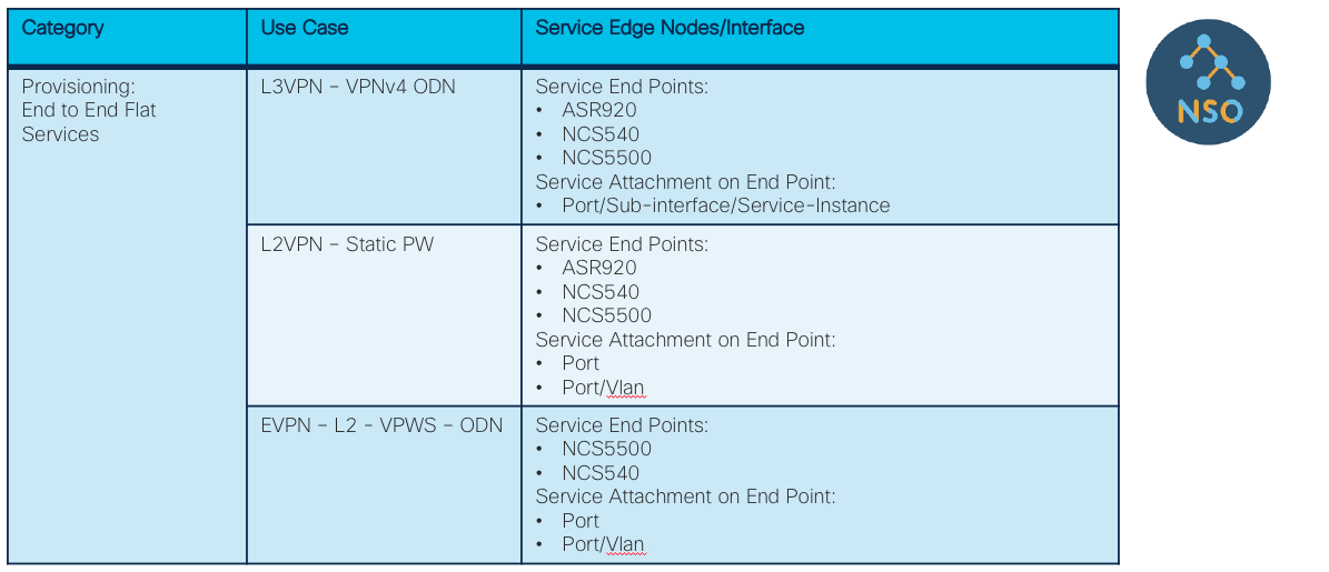
Figure 33: Automation – End-to-End Service Models
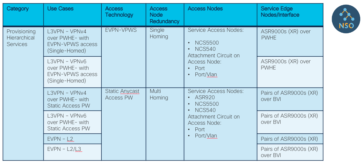
Figure 34: Automation – Hierarchical Service Models
Base Services supporting Advanced Use Cases
Overview
The Converged SDN Transport Design aims to enable simplification across all layers of a Service Provider network. Thus, the Converged SDN Transport services layer focuses on a converged Control Plane based on BGP.
BGP based Services include EVPNs and Traditional L3VPNs (VPNv4/VPNv6).
EVPN is a technology initially designed for Ethernet multipoint services to provide advanced multi-homing capabilities. By using BGP for distributing MAC address reachability information over the MPLS network, EVPN brought the same operational and scale characteristics of IP based VPNs to L2VPNs. Today, beyond DCI and E-LAN applications, the EVPN solution family provides a common foundation for all Ethernet service types; including E-LINE, E-TREE, as well as data center routing and bridging scenarios. EVPN also provides options to combine L2 and L3 services into the same instance.
To simplify service deployment, provisioning of all services is fully automated using Cisco Network Services Orchestrator (NSO) using (YANG) models and NETCONF. Refer to Section: “Network Services Orchestrator (NSO)”.
There are two types of services: End-To-End and Hierarchical. The next two sections describe these two types of services in more detail.
Ethernet VPN (EVPN)
EVPNs solve two long standing limitations for Ethernet Services in Service Provider Networks:
Multi-Homed & All-Active Ethernet Access
Service Provider Network - Integration with Central Office or with Data Center
Ethernet VPN Hardware Support
In CST 3.0 EVPN ELAN, ETREE, and VPWS services are supported on all IOS-XR devices. The ASR920 running IOS-XE does not support native EVPN services, but can integrate into an overall EVPN service by utilizing service hierarchy. Please see the tables under Flat and Hierarchical Services for supported service types. Please note ODN is NOT supported for EVPN ELAN services in IOS-XR 6.6.3.
Multi-Homed & All-Active Ethernet Access
Figure 21 demonstrates the greatest limitation of traditional L2 Multipoint solutions like VPLS.
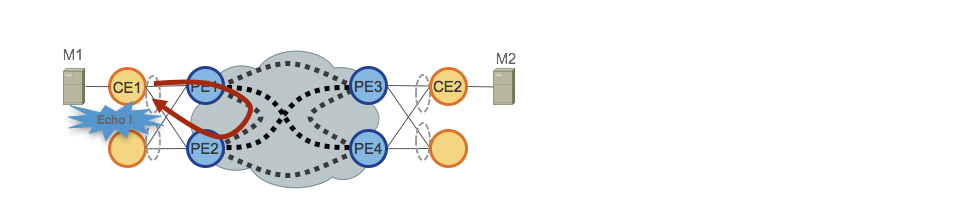
Figure 21: EVPN All-Active Access
When VPLS runs in the core, loop avoidance requires that PE1/PE2 and PE3/PE4 only provide Single-Active redundancy toward their respective CEs. Traditionally, techniques such mLACP or Legacy L2 protocols like MST, REP, G.8032, etc. were used to provide Single-Active access redundancy.
The same situation occurs with Hierarchical-VPLS (H-VPLS), where the access node is responsible for providing Single-Active H-VPLS access by active and backup spoke pseudowire (PW).
All-Active access redundancy models are not deployable as VPLS technology lacks the capability of preventing L2 loops that derive from the forwarding mechanisms employed in the Core for certain categories of traffic. Broadcast, Unknown-Unicast and Multicast (BUM) traffic sourced from the CE is flooded throughout the VPLS Core and is received by all PEs, which in turn flood it to all attached CEs. In our example PE1 would flood BUM traffic from CE1 to the Core, and PE2 would sends it back toward CE1 upon receiving it.
EVPN uses BGP-based Control Plane techniques to address this issue and enables Active-Active access redundancy models for either Ethernet or H-EVPN access.
Figure 22 shows another issue related to BUM traffic addressed by EVPN.
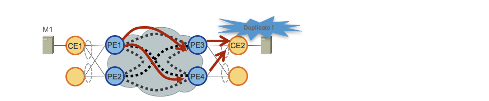
Figure 22: EVPN BUM Duplication
In the previous example, we described how BUM is flooded by PEs over the VPLS Core causing local L2 loops for traffic returning from the core.
Another issue is related to BUM flooding over VPLS Core on remote PEs. In our example either PE3 or PE4 receive and send the BUM traffic to their attached CEs, causing CE2 to receive duplicated BUM traffic.
EVPN also addresses this second issue, since the BGP Control Plane allows just one PE to send BUM traffic to an All-Active EVPN access.
Figure 23 describes the last important EVPN enhancement.
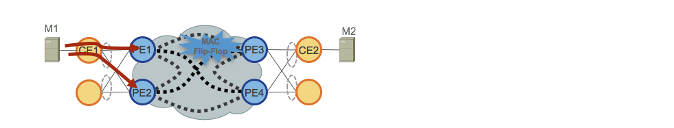
Figure 23: EVPN MAC Flip-Flopping
In the case of All-Active access, traffic is load-balanced (per-flow) over the access PEs (CE uses LACP to bundle multiple physical ethernet ports and uses hash algorithm to achieve per flow load-balancing). Remote PEs, PE3 and PE4, receive the same flow from different neighbors. With a VPLS core, PE3 and PE4 would rewrite the MAC address table continuously, each time the same mac address is seen from a different neighbor.
EVPN solves this by mean of “Aliasing”, which is also signaled via the BGP Control Plane.
Service Provider Network - Integration with Central Office or with Data Center
Another very important EVPN benefit is the simple integration with Central Office (CO) or with Data Center (DC). Note that Metro Central Office design is not covered by this document.
The adoption of EVPNs provides huge benefits on how L2 Multipoint technologies can be deployed in CO/DC. One such benefit is the converged Control Plane (BGP) and converged data plane (SR MPLS/SRv6) over SP WAN and CO/DC network.
Moreover, EVPNs can replace existing proprietary Ethernet Multi-Homed/All-Active solutions with a standard BGP-based Control Plane.
End-To-End (Flat) – Services
The End-To-End Services use cases are summarized in the table in Figure 24 and shown in the network diagram in Figure 25.
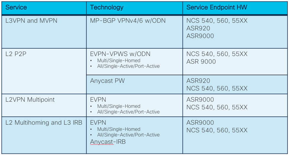
Figure 24: End-To-End – Services table
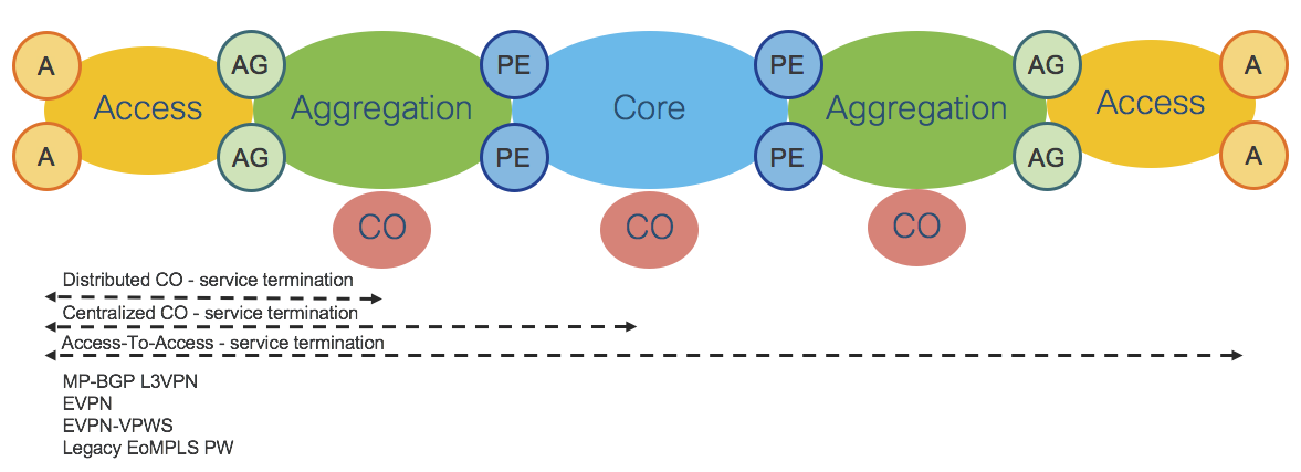
Figure 25: End-To-End – Services
All services use cases are based on BGP Control Plane.
Refer also to Section: “Transport and Services Integration”.
Hierarchical – Services
Hierarchical Services Use Cases are summarized in the table of Figure 26 and shown in the network diagram of Figure 27.
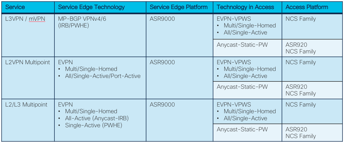
Figure 26: Hierarchical – Services table
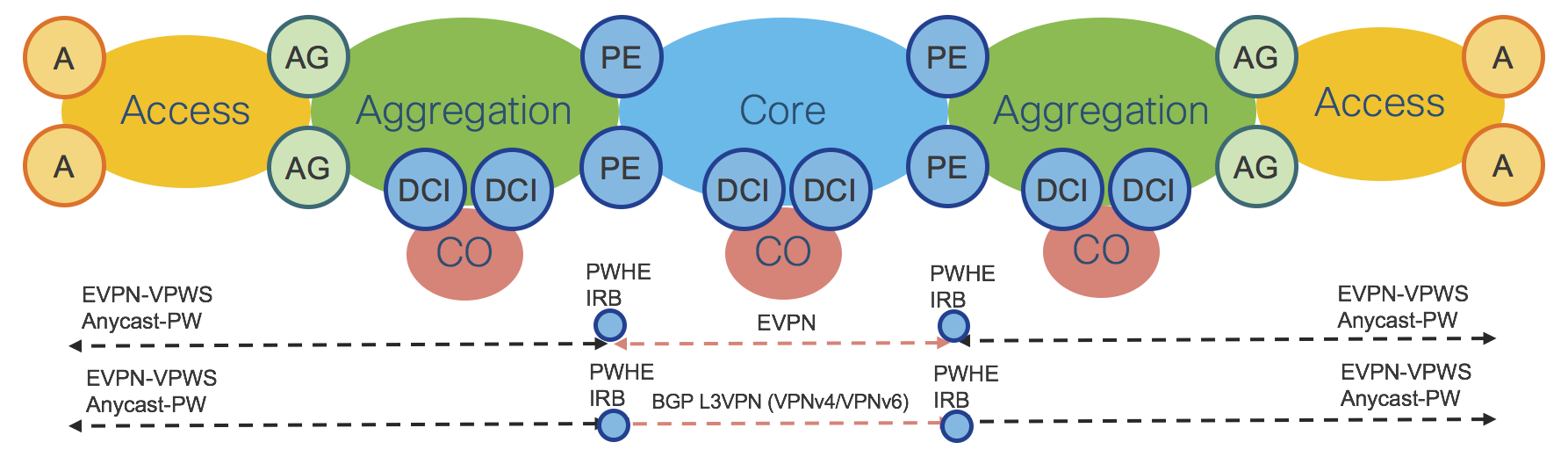
Figure 27: Hierarchical - Services
Hierarchical services designs are critical for Service Providers looking for limiting requirements on the access platforms and deploying more centralized provisioning models that leverage very rich features sets on a limited number of touch points.
Hierarchical Services can also be required by Service Providers who want to integrate their SP-WAN with the Central Office/Data Center network using well-established designs based on Data Central Interconnect (DCI).
Figure 27 shows hierarchical services deployed on PE routers, but the same design applies when services are deployed on AG or DCI routers.
The Converged SDN Transport Design offers scalable hierarchical services with simplified provisioning. The three most important use cases are described in the following sections:
Hierarchical L2 Multipoint Multi-Homed/All-Active
Hierarchical L2/L3 Multi/Single-Home, All/Single-Active Service (H-EVPN) and Anycast-IRB
Hierarchical L2/L3 Multipoint Multi-Homed/Single-Active (H-EVPN) and PWHE
Hierarchical L2 Multipoint Multi-Homed/All-Active
Figure 28 shows a very elegant way to take advantage of the benefits of Segment-Routing Anycast-SID and EVPN. This use case provides Hierarchical L2 Multipoint Multi-Homed/All-Active (Single-Homed Ethernet access) service with traditional access router integration.
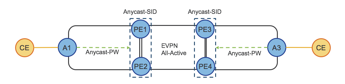
Figure 28: Hierarchical – Services (Anycast-PW)
Access Router A1 establishes a Single-Active static pseudowire (Anycast-Static-PW) to the Anycast IP address of PE1/PE2. PEs anycast IP address is represented by Anycast-SID.
Access Router A1 doesn’t need to establish active/backup PWs as in a traditional H-VPLS design and doesn’t need any enhancement on top of the established spoke pseudowire design.
PE1 and PE2 use BGP EVPN Control Plane to provide Multi-Homed/All-Active access, protecting from L2 loop, and providing efficient per-flow load-balancing (with aliasing) toward the remote PEs (PE3/PE4).
A3, PE3 and PE4 do the same, respectively.
Hierarchical L2/L3 Multi/Single-Home, All/Single-Active Service (H-EVPN) and Anycast-IRB
Figure 29 shows how EVPNs can completely replace the traditional H-VPLS solution. This use case provides the greatest flexibility as Hierarchical L2 Multi/Single-Home, All/Single-Active modes are available at each layer of the service hierarchy.
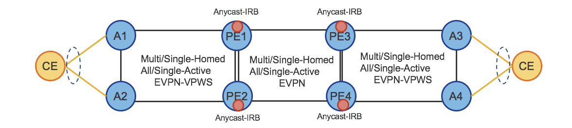
Figure 29: Hierarchical – Services (H-EVPN)
Optionally, Anycast-IRB can be used to enable Hierarchical L2/L3 Multi/Single-Home, All/Single-Active service and to provide optimal L3 routing.
Hierarchical L2/L3 Multipoint Multi-Homed/Single-Active (H-EVPN) and PWHE
Figure 30 shows how the previous H-EVPN can be extended by taking advantage of Pseudowire Headend (PWHE). PWHE with the combination of Multi-Homed, Single-Active EVPN provides an Hierarchical L2/L3 Multi-Homed/Single-Active (H-EVPN) solution that supports QoS.
It completely replaces traditional H-VPLS based solutions. This use case provides Hierarchical L2 Multi/Single-Home, All/Single-Active service.
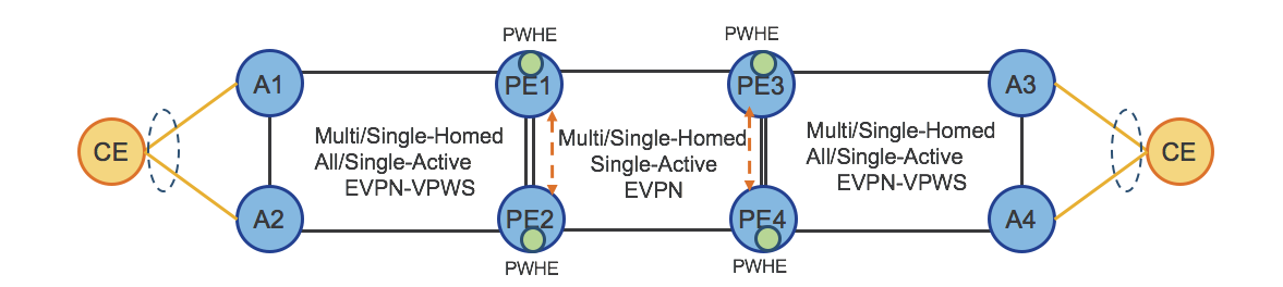
Figure 30: Hierarchical – Services (H-EVPN and PWHE)
Refer also to the section: “Transport and Services Integration”.
Services – Route-Reflector (S-RR)
Figure 31 shows the design of Services Router-Reflectors (S-RRs).
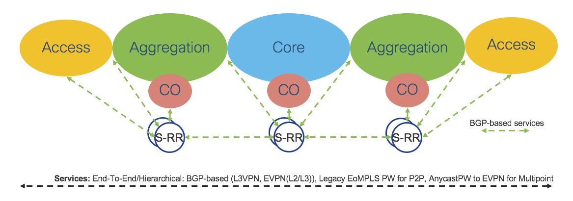
Figure 31: Services – Route-Reflectors
The Converged SDN Transport Design focuses mainly on BGP-based services, therefore it is important to provide a robust and scalable Services Route-Reflector (S-RR) design.
For Redundancy reasons, there are at least 2 S-RRs in any given IGP Domain, although Access and Aggregation are supported by the same pair of S-RRs.
Each node participating in BGP-based service termination has two BGP sessions with Domain Specific S-RRs and supports multiple address-Families: VPNv4, VPNv6, EVPN.
Core Domain S-RRs cover the core Domain. Aggregation Domain S-RRs cover Access and Aggregation Domains. Aggregation Domain S-RRs and Core S-RRs have BGP sessions among each other.
The described solution is very scalable and can be easily extended to scale to higher numbers of BGP sessions by adding another pair of S-RRs in the Access Domain.
Ethernet Services OAM using Ethernet CFM
Ethernet CFM using 802.1ag/Y.1731 has been added in the CST 3.0 design. Ethernet CFM provides end-to-end continuity monitoring and alerting on a per-service basis. Maintenance End Points (MEPs) are configured on PE-CE interfaces with periodic Continuity Check Messages (CCMs) sent between them utilizing the same forwarding path as service traffic. Ethernet CFM also enables the transmission of Alarm Indication Signal (AIS) messages to alert remote endpoints of local faults. Additional information on Ethernet CFM can be found in the CST Implementation Guide at https://xrdocs.io/design/blogs/latest-converged-sdn-transport-implementation-guide
Transport and Services Integration
Section: “Transport - Design” described how Segment Routing provides flexible End-To-End and Any-To-Any Highly-Available transport together with Fast Re-Route. A converged BGP Control Plane provides a scalable and flexible solution also at the services layer.
Figure 35 shows a consolidated view of the Converged SDN Transport network from a Control-Plane standpoint. Note that while network operators could use both PCEP and BGR-SR-TE at the same time, it is not typical.
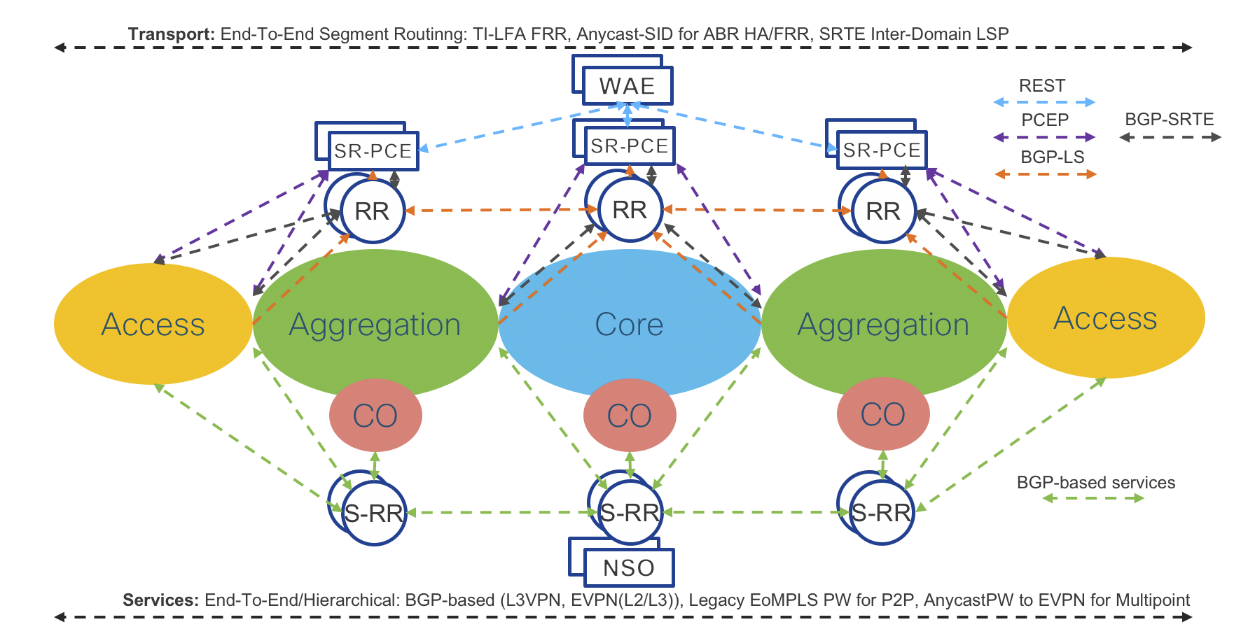
Figure 35: Converged SDN Transport – Control-Plane
As mentioned, service provisioning is independent of the transport layer. However, transport is responsible for providing the path based on service requirements (SLA). The component that enables such integration is On-Demand Next Hop (ODN). ODN is the capability of requesting to a controller a path that satisfies specific constraints (such as low latency). This is achieved by associating an SLA tag/attribute to the path request. Upon receiving the request, the SR-PCE controller calculates the path based on the requested SLA and use PCEP or BGP-SR-TE to dynamically program the Service End Point with a specific SR-TE Policy.
The Converged SDN Transport design also use MPLS Performance Management to monitor link delay/jitter/drop (RFC6374) to be able to create a Low Latency topology dynamically.
Figure 36 shows a consolidated view of the Converged SDN Transport network from a Data Plane standpoint.
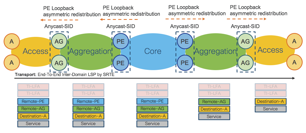
Figure 36: Converged SDN Transport – Data-Plane
The Converged SDN Transport Design
Transport
This section describes in detail the Converged SDN Transport design. This Converged SDN Transport design focuses on transport programmability using Segment Routing and BGP-based services adoption.
Figure 35 and Figure 36 show the network topology and transport Data Plane details for Phase 1. Refer also to the Access domain extension use case in Section: “Use Cases”.
The network is split into Access and Core IGP domains. Each IGP domain is represented by separate IGP processes. The Converged SDN Transport design uses ISIS IGP protocol for validation.
Validation will be done on two types of access platforms, IOS-XR and IOS-XE, to prove interoperability.
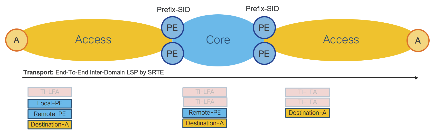
Figure 37: Access Domain Extension – End-To-End Transport
For the End-To-End LSP shown in Figure 35, the Access Router imposes 3 transport labels (SID-list) An additional label, the TI-LFA label, can be also added for FRR (node and link protection). In the Core and in the remote Access IGP Domain, 2 additional TI-LFA labels can be used for FRR (node and link protection). In Phase 1 PE ABRs are represented by Prefix-SID. Refer also to Section: “Transport Programmability - Phase 1”.
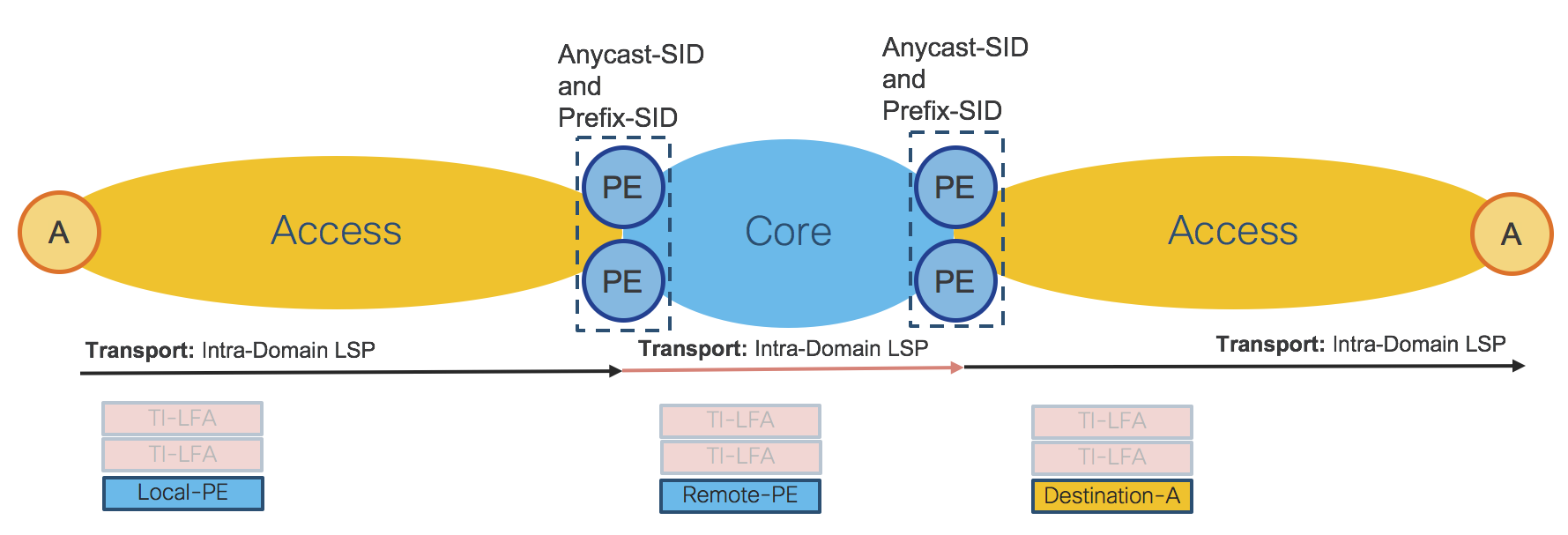
Figure 38: Access Domain Extension – Hierarchical Transport
Figure 38 shows how the Access Router imposes a single transport label to reach local PE ABRs, where the hierarchical service is terminated. Similarly, in the Core and in the remote Access IGP domain, the transport LSP is contained within the same IGP domain (Intra-Domain LSP). Routers in each IGP domain can also impose two additional TI-LFA labels for FRR (to provide node and link protection).
In the Hierarchical transport use case, PE ABRs are represented by Anycast-SID or Prefix-SID. Depending on the type of service, Anycast-SID or Prefix-SID is used for the transport LSP.
Transport Programmability
The Converged SDN Transport employs a distributed and highly available SR-PCE design as described in Section: “Transport Programmability”. Transport programmability is based on PCEP. Figure 39 shows the design when SR-PCE uses PCEP.

Figure 39: SR-PCE – PCEP
SR-PCE in the Access domain is responsible for Inter-Domain LSPs and provides the SID-list. PE ABRs are represented by Prefix-SID.
SR-PCE in the Core domain is responsible for On-Demand Nexthop (ODN) for hierarchical services. Refer to the table in Figure 41 to see what services use ODN. Refer to Section: “Transport Controller - Path Computation Engine (PCE)” to see more details about XR Transport Controller (SR-PCE). Note that Phase 1 uses the “Delegated Computation to SR-PCE” mode described in Section: “Path Computation Engine - Workflow” without WAE as shown in Figure 38.
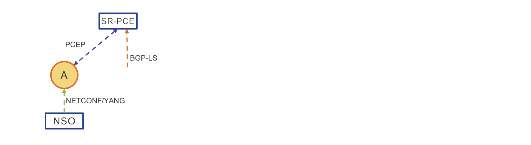
Figure 40: PCE Path Computation – Phase 1
Delegated Computation to SR-PCE
NSO provisions the service – Service can also be provisioned via CLI
Access Router requests a path
SR-PCE computes the path
SR-PCE provides the path to Access Router
Access Router confirms
Services
This section describes the Services used in the Converged SDN Transport Phase 1.
The table in Figure 41 describes the End-To-End services, while the network diagram in Figure 42 shows how services are deployed in the network. Refer also to Section: “Services - Design” of this document.
Figure 41: End-To-End Services table
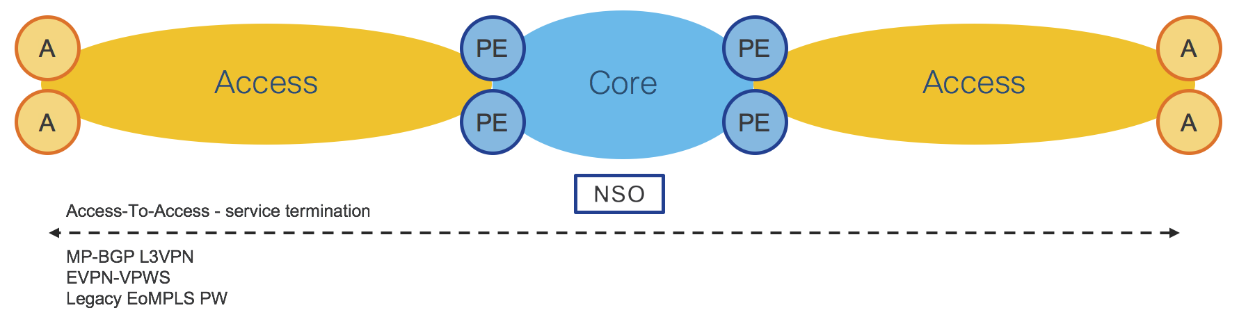
Figure 42: End-To-End Services
The table in Figure 43 describes the hierarchical services, while the network diagram in Figure 44 shows how services are deployed in the network. Refer also to Section: “Services - Design” of this document.
In addition, the table in Figure 44 shows where PE ABRs Anycast-SID is required and where ODN in the Core IGP domain is used.
Figure 43: Hierarchical Services table
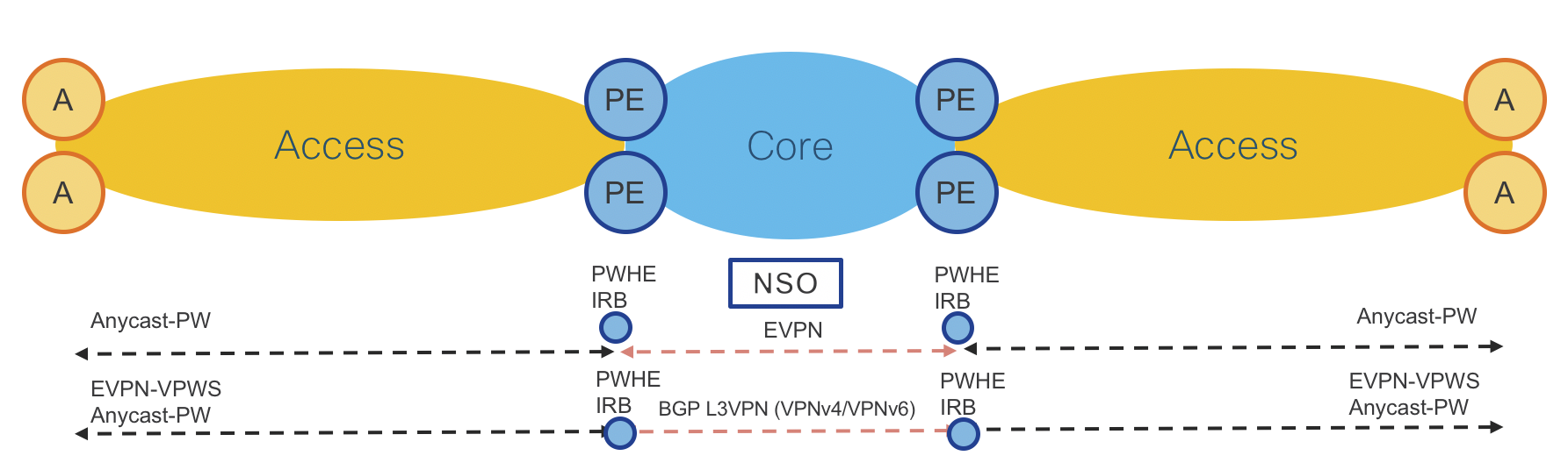
Figure 44: Hierarchical Services
The Converged SDN Transport uses the hierarchical Services Route-Reflectors (S-RRs) design described in Section: “Services - Route-Reflector (S-RR)”. Figure 45 shows in detail the S-RRs design used for Phase 1.
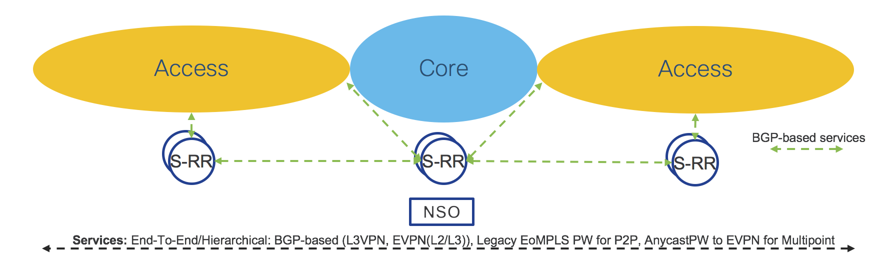
Figure 45: Services Route-Reflectors (S-RRs)
Network Services Orchestrator (NSO) is used for service provisioning. Refer to Section: “Network Services Orchestrator (NSO)”.
Transport and Services Integration
Transport and Services integration is described in Section: “Transport and Services Integration” of this document. Figure 46 shows an example of End-To-End LSP and services integration.
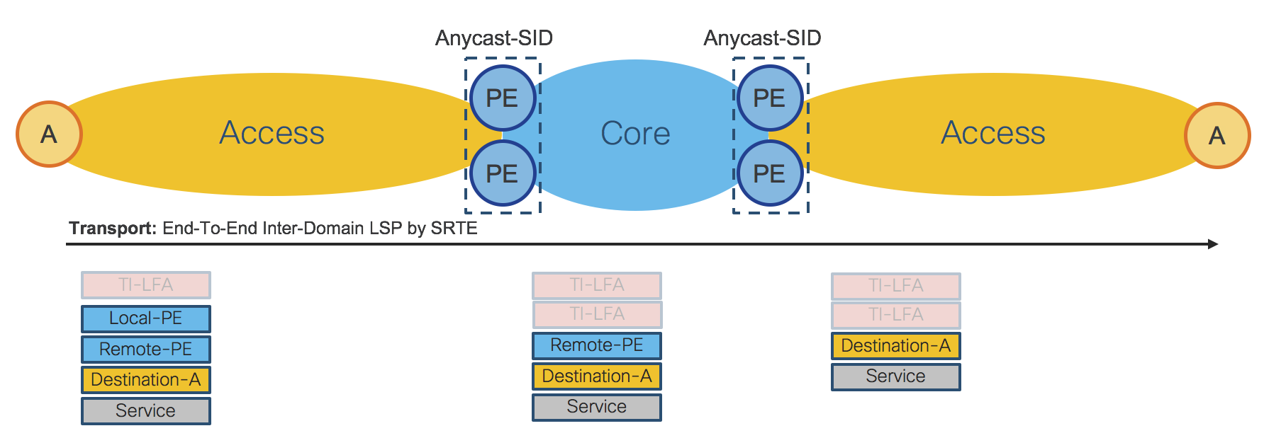
Figure 46: Transport and Services Data-Plane
Figure 47 shows a consolidated view of the Transport and Services Control-Plane.
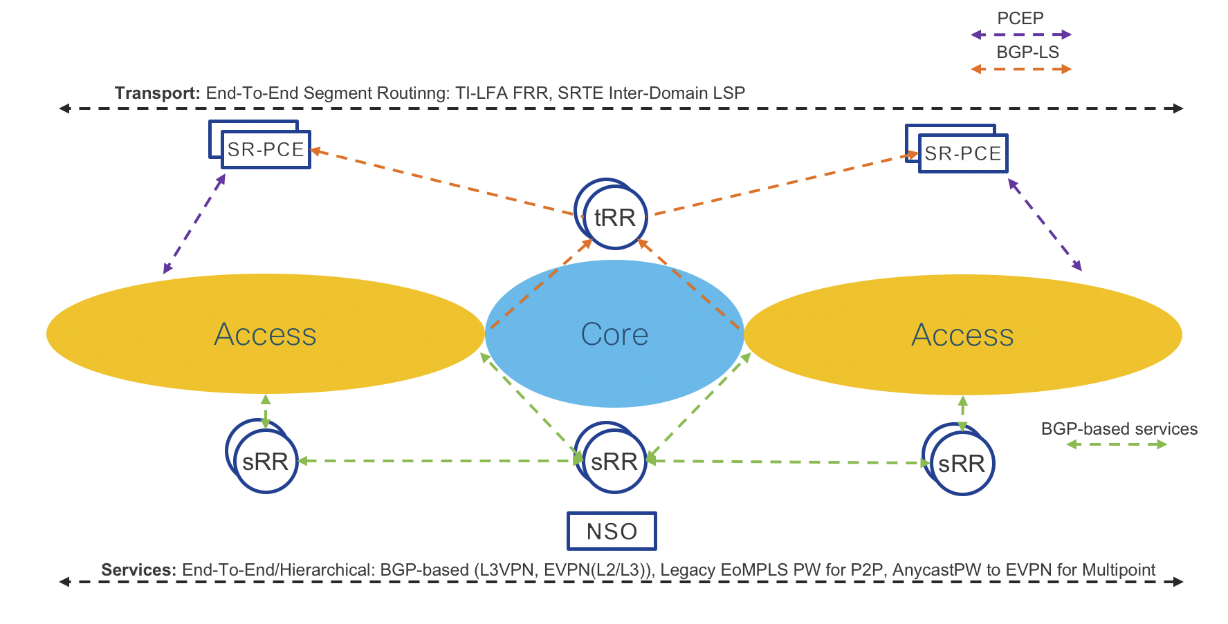
Figure 47: Transport and Services Control-Plane
Figure 48 shows the detailed topology of the testbed used for validation.
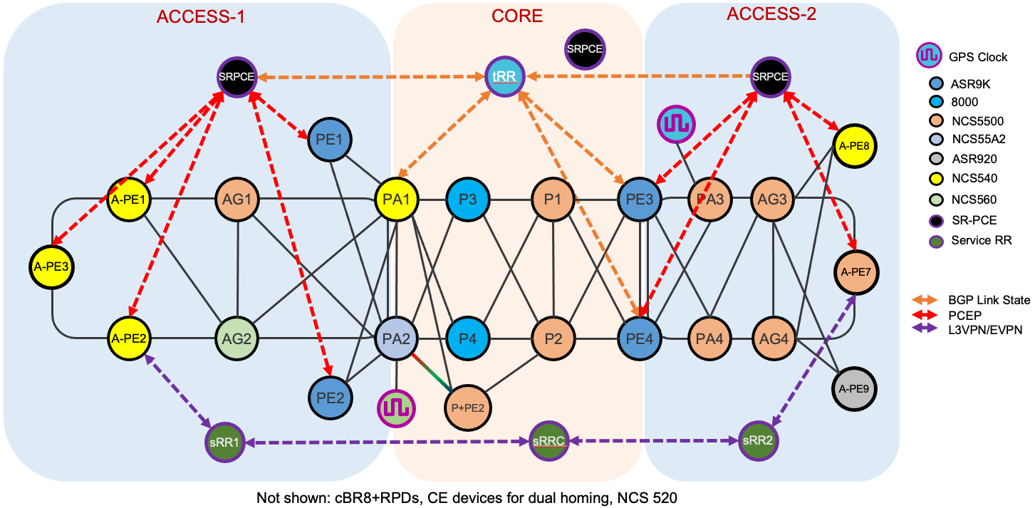
Figure 48: Testbed
Figure 49 shows the detailed topology of the testbed used for CIN and Remote PHY validation.
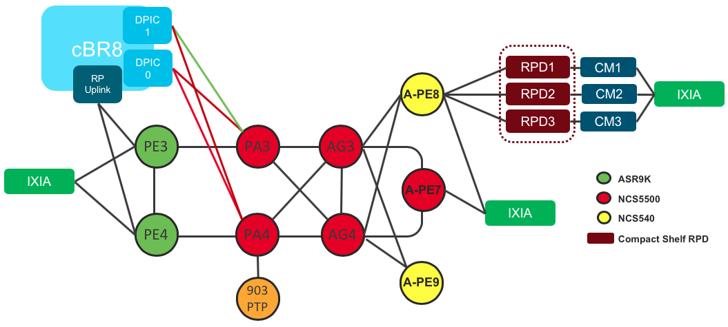
Figure 49: Remote PHY/CIN Validation Testbed
The Converged SDN Transport Design - Summary
The Converged SDN Transport brings huge simplification at the Transport as well as at the Services layers of a Service Provider network. Simplification is a key factor for real Software Defined Networking (SDN). Cisco continuously improves Service Provider network designs to satisfy market needs for scalability and flexibility.
From a very well established and robust Unified MPLS design, Cisco has embarked on a journey toward transport simplification and programmability, which started with the Transport Control Plane unification in Evolved Programmable Network 5.0 (EPN5.0). The Cisco Converged SDN Transport provides another huge leap forward in simplification and programmability adding Services Control Plane unification and centralized path computation.
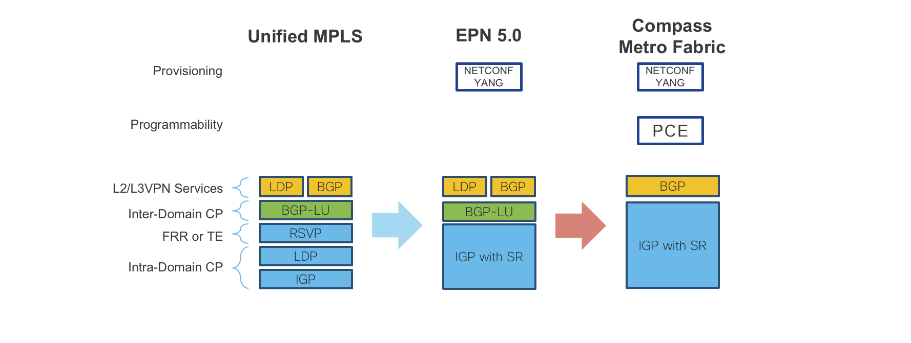
Figure 50: Converged SDN Transport – Evolution
The transport layer requires only IGP protocols with Segment Routing extensions for Intra and Inter Domain forwarding. Fast recovery for node and link failures leverages Fast Re-Route (FRR) by Topology Independent Loop Free Alternate (TI-LFA), which is a built-in function of Segment Routing. End to End LSPs are built using Traffic Engineering by Segment Routing, which does not require additional signaling protocols. Instead it solely relies on SDN controllers, thus increasing overall network scalability. The controller layer is based on standard industry protocols like BGP-LS, PCEP, BGP-SR-TE, etc., for path computation and NETCONF/YANG for service provisioning, thus providing a on open standards based solution.
For all those reasons, the Cisco Converged SDN Transport design really brings an exciting evolution in Service Provider Networking.
Leave a Comment