
Cisco Routed Optical Networking
Revision History
| Version | Date | Comments |
|---|---|---|
| 1.0 | 01/10/2022 | Initial Routed Optical Networking Publication |
Solution Component Software Versions
| Element | Version |
|---|---|
| IOS-XR | 7.3.2 |
| IOS-XR (NCS 540) | 7.4.1 |
| NCS 2000 SVO | 12.2 |
| Cisco Optical Network Controller | 1.1 |
| Crosswork Network Controller | 3.0 |
| Crosswork Hierarchical Controller | 5.1 |
| Cisco EPNM | 5.1.3 |
What is Routed Optical Networking?
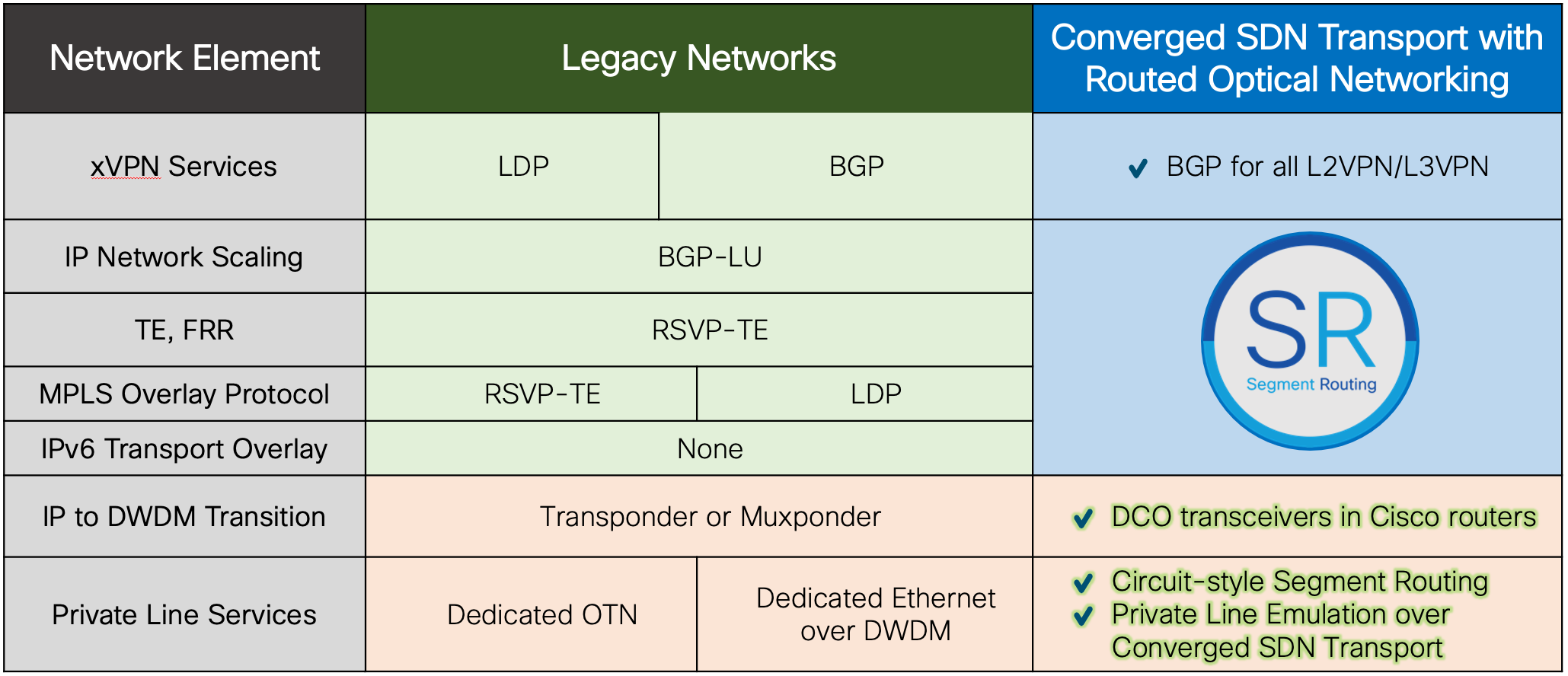
Routed Optical Networking as part of Cisco’s Converged SDN Transport architecture brings network simplification to the physical network infrastructure, just as EVPN and Segment Routing simplify the service and traffic engineering network layers. Routed Optical Networking collapses complex technologies and network layers into a single cost efficient and easy to manage network infrastructure. Here we present the Cisco Routed Optical Networking architecture and validated design.
Key Drivers
Changing Networks
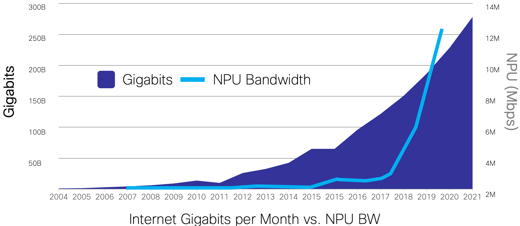
Internet traffic has seen a compounded annual growth rate of 30% or higher over the last ten years, as more devices are connected, end user bandwidth speeds increase, and applications continue to move to the cloud. The introduction of 5G in mobile carriers and backhaul providers is also a disruptor, networks must be built to handle the advanced services and traffic increase associated with 5G. Networks must evolve so the infrastructure layer can keep up with the service layer. 400G Ethernet is the next evolution for SP IP network infrastructure, and we must make that as efficient as possible.
Network Complexity
Computer networks at their base are a set of interconnected nodes to deliver data between two endpoints. In the very beginning, these networks were designed using a layered approach to separate functions. The OSI model is an example of how functional separation has led to innovation by allowing different standards bodies to work in parallel at each layer. In some cases even these OSI layers are further split into different layers. While these layers can bring some cost benefit, it also brings added complexity. Each layer has its own management, control plane, planning, and operational model.
Inefficiences Between Network Layers
OTN and IP network traffic must be converted into wavelength signals to traverse the DWDM network. This has traditionally required dedicated external hardware, a transponder. All of these layers bring complexity, and today some of those layers, such as OTN, bring little to the table in terms of efficiency or additional value. OTN switching, like ATM previously, has not been able to keep up with traffic demands due to very complex hardware. Unlike Ethernet/IP, OTN also does not have a widely interoperable control plane, locking providers into a single vendor or solution long-term.
Operational Complexity
Networks involving opaque layers are difficult to plan, build, and operate. IP and optical networks often have duplicate teams covering similar tasks. Network protection and restoration is also often complicated by different schemes running independently across layers. The industry has tried over decades to solve some of these issues with complex control planes such as GMPLS, but we are now at an evolution point where simplifying the physical layers and reducing control plane complexity in the optical layer allows a natural progression to a single control-plane and protection/restoration layer.
Network Cost
Simplyfing networks reduces both capex and opex. As we move to 400G, the network cost is shifted away from routers and router ports to optics. Any way we can reduce the number of 400G interconnects on the network will greatly reduce cost. Modeling networks with 400ZR and OpenZR+ optics in place of traditional transponders and muxponders shows this in almost any network scenario. It also results in a reduced space and power footprint.
Routed Optical Networking Solution Overview
As part of the Converged SDN Transport architecture, Routed Optical Networking extends the key tenet of network simplification. Routed Optical Networking tackles the challenges of building and managing networks by simplifying both the infrastructure and operations.
Today’s Complex Multi-Layer Network Infrastructure

DWDM
Most modern SP networks start at the physical fiber optic layer. Above the physical fiber is technology to allow multiple photonic wavelengths to traverse a single fiber and be switched at junction points, we will call that the DWDM layer.
OTN
In some networks, above this DWDM layer is an OTN layer, OTN being the evolution of traditional SONET/SDH networks. OTN grooms low speed TDM services into higher speed containers, and if OTN switching is involved, allows switching these services at intermediate points in the network. OTN is primarily used in network to carry guaranteed bandwidth services.
Ethernet/IP
In all high bandwidth networks today, there is an Ethernet layer on which IP services traverse, since almost all data traffic today is IP. Ethernet and IP is used due to its ability to support statistical multiplexing, topology flexibility, and widespread interoperability between different vendors based on well-defined standards. In larger networks today carrying Internet traffic, the Ethernet/IP layer does not typically traverse an OTN layer, the OTN layer is primarily used only for business services.
Enabling Technologies
Pluggable Digital Coherent Optics
Simple networks are easier to build and easier to operate. As networks scale to handle traffic growth, the level of network complexity must decline or at least remain flat.
IPoDWDM has attempted to move the transponder function into the router to remove the transponder and add efficiency to networks. In lower bandwidth applications, it has been a very successful approach. CWDM, DWDM SFP/SFP+, and CFP2-DCO pluggable transceivers have been used for many years now to build access, aggregation, and lower speed core networks. The evolution to 400G and advances in technology created an opportunity to unlock this potential in higher speed networks.
Transponder or muxponders have typically been used to aggregate multiple 10G or 100G signals into a single wavelength. However, with reach limitations, and the fact transponders are still operating at 400G wavelength speeds, the transponder becomes a 1:1 input to output stage in the network, adding no benefit.
The Routed Optical Networking architecture unlocks this efficiency for networks of all sizes, due to advancements in coherent plugable technology.
QSFP-DD and 400ZR and OpenZR+ Standards
As mentioned, the industry saw a point to improve network efficiency by shifting coherent DWDM functions to router pluggables. Technology advancements have shrunk the DCO components into the standard QSFP-DD form factor, meaning no specialized hardware and the ability to use the highest capacity routers available today. ZR/OpenZR+ QSFP-DD optics can be used in the same ports as the highest speed 400G non-DCO transceivers.
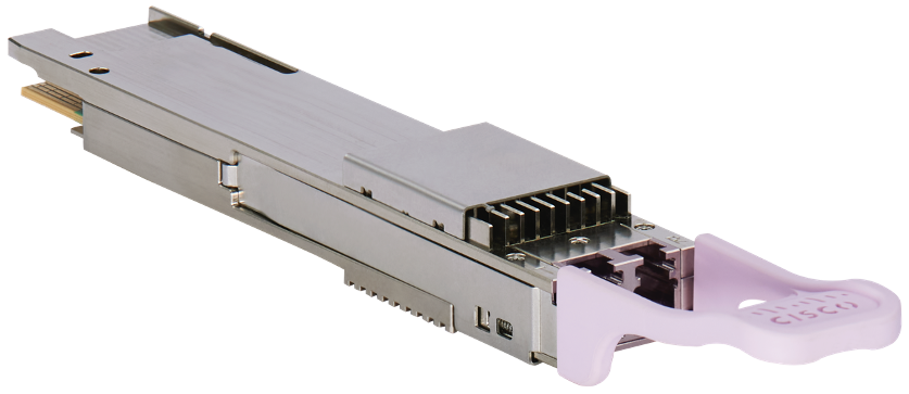
Cisco OpenZR+ Transceiver (QDD-400G-ZRP-S)
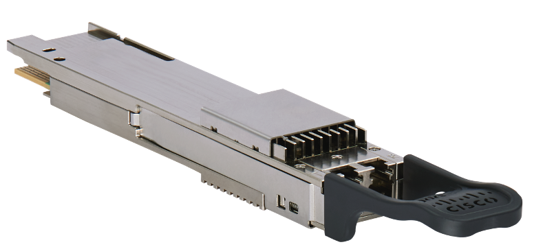
Cisco OIF 400ZR Transceiver (QDD-400G-ZR-S)
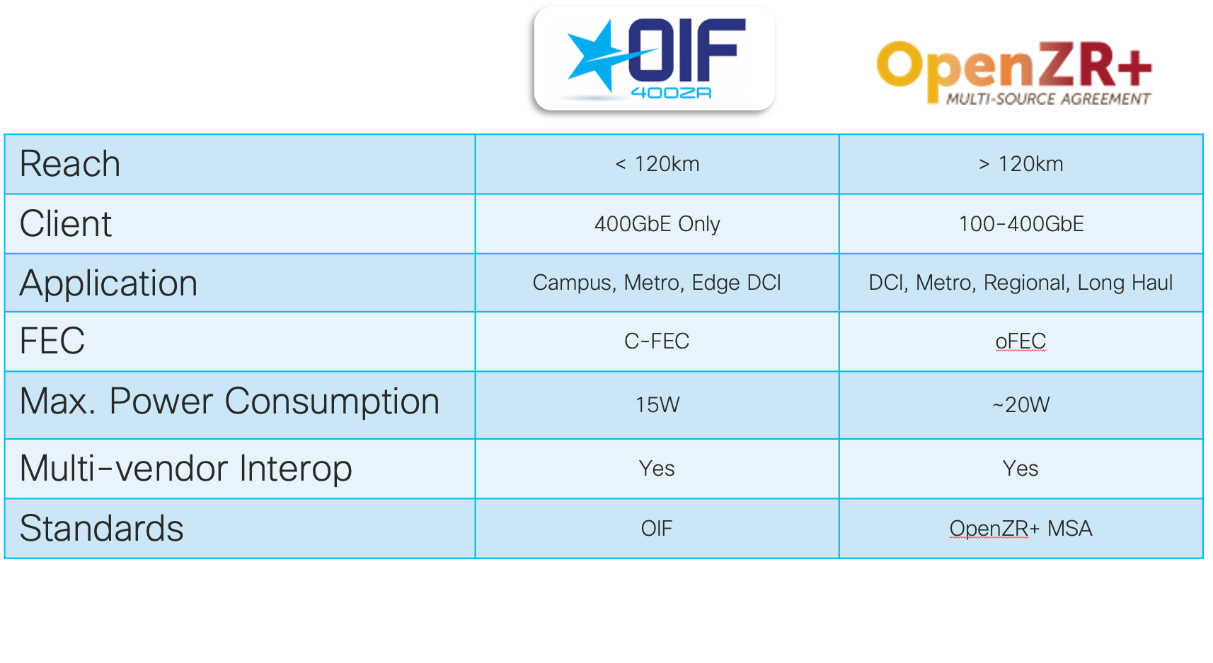
Two industry optical standards have emerged to cover a variety of use cases. The OIF created the 400ZR specification, https://www.oiforum.com/technical-work/hot-topics/400zr-2 as a 400G interopable standard for metro reach coherent optics. The industry saw the benefit of the approach, but wanted to cover longer distances and have flexibility in wavelength rates, so the OpenZR+ MSA was created, https://www.openzrplus.org. The following table outlines the specs of each standard. ZR400 and OpenZR+ transceivers are tunable across the ITU C-Band, 196.1 To 191.3 THz.
The following part numbers are used for Cisco’s ZR400 and OpenZR+ MSA transceivers
| Standard | Part |
|---|---|
| 400ZR | QDD-400G-ZR-S |
| OpenZR+ | QDD-400G-ZRP-S |
Cisco datasheet for these transceivers can be found at https://www.cisco.com/c/en/us/products/collateral/interfaces-modules/transceiver-modules/datasheet-c78-744377.html
Cisco Routers
We are at a point in NPU development where the pace of NPU bandwidth growth has outpaced network traffic growth. Single NPUs such as Cisco’s Silicon One have a capacity exceeding 12.8Tbps in a single NPU package without sacrificing flexibility and rich feature support. This growth of NPU capacity also brings reduction in cost, meaning forwarding traffic at the IP layer is more advantageous vs. a network where layer transitions happen often.
Cisco supports 400ZR and OpenZR+ optics across the NCS 540, NCS 5500, NCS 5700, ASR 9000, and Cisco 8000 series routers. This enabled providers to utilize the architecture across their end to end infrastructure in a variety of router roles. See
Cisco DWDM Network Hardware
Routed Optical Networking shifts an expensive and now often redundant transponder function into a pluggable transceiver. However, to make the most efficient use of a valuable resource, the underlying fiber optic network, we still need a DWDM layer. Routed Optical Networking is flexible enough to work across point to point, ROADM based optical networks, or a mix of both. Cisco multiplexers, amplifiers, and ROADMs can satisfy any network need. See the validated design hardware section for more information.
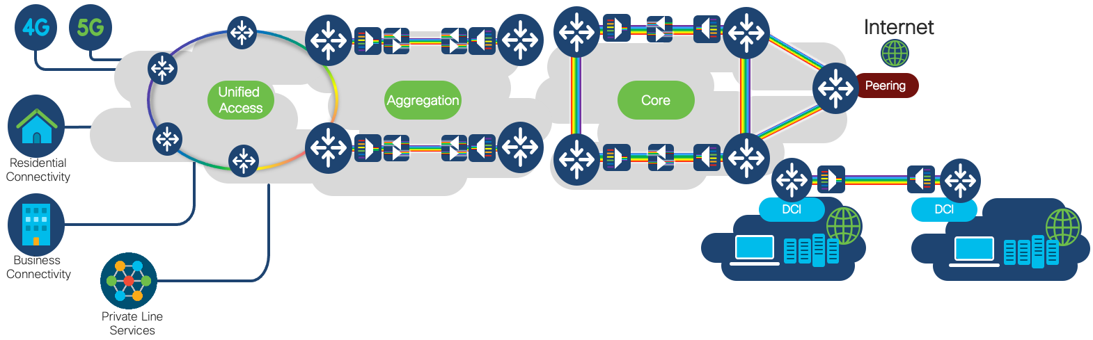
Routed Optical Networking Network Use Cases
Cisco is embracing Routed Optical Networking in every SP router role. Access, aggregation, core, peering, DCI, and even PE routers can be enabled with high speed DCO optics. Routed Optical Networking is also not limited to SP networks, there are applications across enterprise, government, and education networks.
Where to use 400ZR and where to use OpenZR+
The OIF 400ZR and OpenZR+ MSA standards have important differences.
400ZR supports 400G rates only, and targets metro distance point to point connections up to 120km. 400ZR mandates a strict power consumption of 15W as well. Networks requiring only 400G over distances less than 120km may benefit from using 400ZR optics. DCI and 3rd party peering interconnection are good use cases for 400ZR.
If a provider needs flexibility in rates and distances and wants to standardize on a single optics type, OpenZR+ can fulfill the need. In areas of the network where 400G may not be needed, OpenZR+ optics can be run at 100G or 200G. Additionally, hardware with QSFP-DD 100G ports can utilize OpenZR+ optics in 100G mode. This can be ideal for high density access and aggregation networks.
Supported DWDM Optical Topologies
For those unfamiliar with DWDM hardware, please see the overview of DWDM network hardware in Appendix A
The future of networks may be a flat L3 network with simple point to point interconnection, but it will take time to migrate to this type of architecture. Routed Optical Network supports an evolution to the architecture by working over most modern photonic DWDM networks. Below gives just a few of the supported optical topologies including both point to point and ROADM networks.
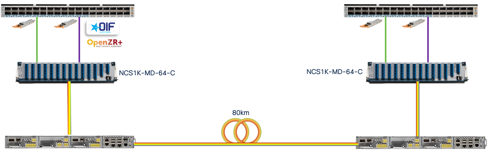
64 Channel FOADM P2P Deployment
This example provides up to 25.6Tb on a single network span, and highlights the simplicity of the Routed Optical Networking solution. The “optical” portion of the network including the ZR/ZR+ configuration can be completed in a matter of minutes from start to finish.
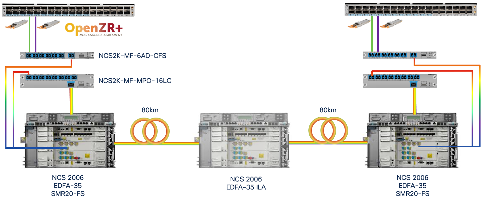
Colorless Add/Drop Deployment
Using the NCS2K-MF-6AD-CFS colorless NCS2K-MF-LC module along with the LC16 LC aggregation module, and SMR20-FS ROADM module, a scalable colorless add/drop complex can be deployed to support 400ZR and OpenZR+.
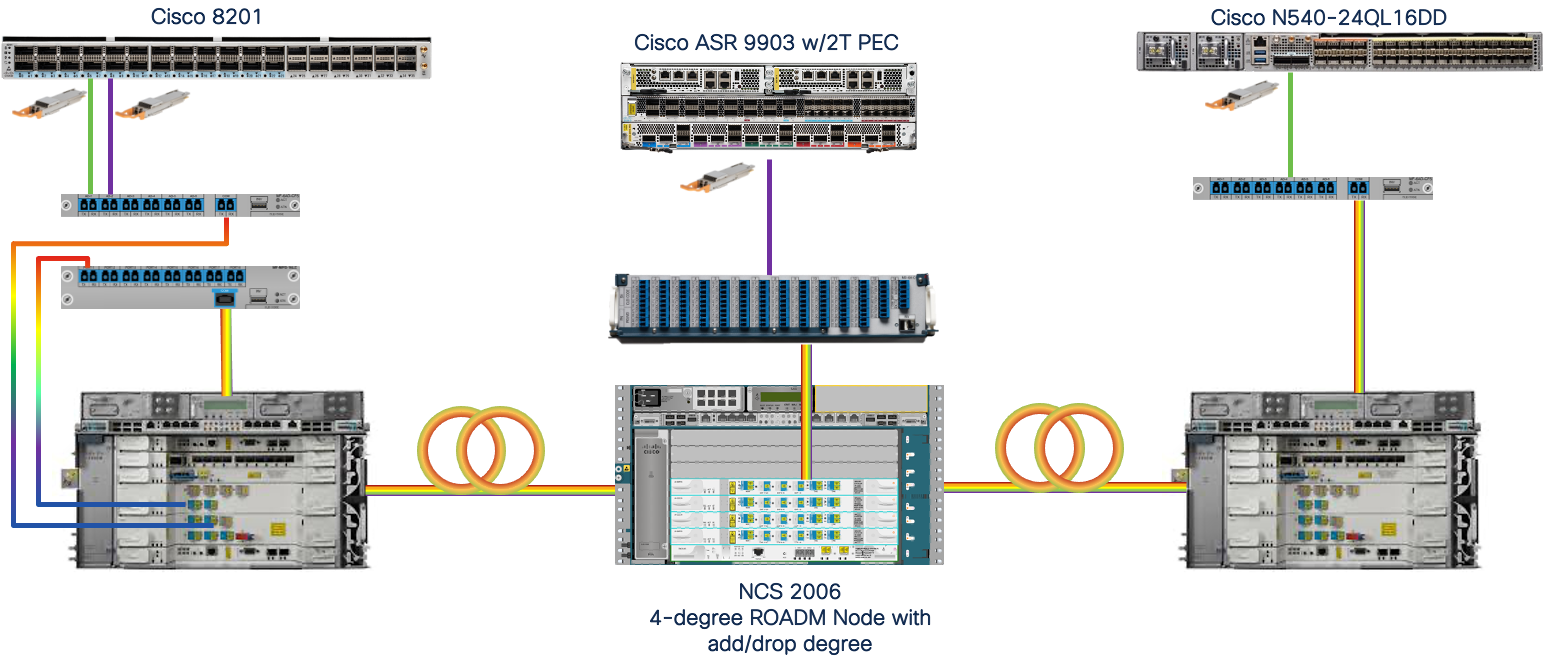
Multi-Degree ROADM Deployment
In this example a 3 degree ROADM node is shown with a local add/drop degree. The Routed Optical Networking solution fully supports ROADM based networks with optical bypass. The traffic demands of the network will dictate the most efficient network build. In cases where an existing or new build requires DWDM switching capability, ZR and ZR+ wavelengths are easily provisioned over the infrastructure.
Long-Haul Deployment
Cisco has demonstrated in a physical lab 400G OpenZR+ services provisioned across 1200km using NCS 2000 optical line systems. 300G, 200G, and 100G signals can achieve even greater distances. OpenZR+ is not just for shorter reach applications, it fulfills an ideal sweet spot in most provider networks in terms of bandwidth and reach.
Core Networks
Long-haul core networks also benefit from the CapEx and OpEx savings of moving to Routed Optical Networking. Moving to a simpler IP enabled converged infrastructure makes networks easier to manage and operate vs. networks with complex underlying optical infrastructure. The easiest place to start in the journey is replacing external transponders with OpenZR+ QSFP-DD transceivers. At 400G connecting a 400G gray Ethernet port to a transponder with a 400G or 600G line side is not cost or environmentally efficient. Cisco can assist in modeling your core network to determine the TCO of Routed Optical Networking compared to traditional approaches.
Metro Aggregation
Tiered regional or metro networks connecting hub locations to larger aggregation site or datacenters can also benefit from Routed Optical Networking. Whether deployed in a hub and spoke topology or hop by hop IP ring, Routed Optical Networking satisfied provider’s growth demands at a lower cost than traditional approaches.
Access
Access deployments in a ring or point-to-point topology are ideal for Routed Optical Networking. Shorter distances over dark fiber may not require active optical equipment, and with up to 400G per span may provide the bandwidth necessary for growth over a number of years without the use of additional multiplexers.
DCI and 3rd Party Location Interconnect
In this use case, Routed Optical Networking simplifies deployments by eliminating active transponders, reducing power, space, and cabling requirements between end locations. 25.6Tbps of bandwidth is available over a single fiber using 64 400G wavelengths and simple optical amplifiers and multiplexers requiring no additional configuration after initial turn-up.
Routed Optical Networking Architecture Hardware
All Routed Optical Networking solution routers are powered by Cisco IOS-XR.
Routed Optical Networking Validated Routers
Below is a non-exhaustive snapshot of platforms validated for use with ZR and OpenZR+ transceivers. Cisco supports Routed Optical Networking in the NCS 540, NCS 5500/5700, ASR 9000, and Cisco 8000 router families. The breadth of coverage enabled the solution across all areas of the network.
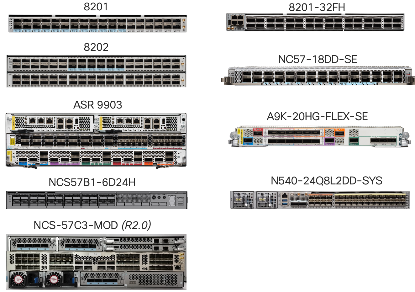
Cisco 8000 Series
The Cisco 8000 and its Silicone One NPU represents the next generation in routers, unprecedented capacity at the lowest power consumption while supporting a rich feature set applicable for a number of network roles.
See more information on Cisco 8000 at https://www.cisco.com/c/en/us/products/collateral/routers/8000-series-routers/datasheet-c78-742571.html
Specific information on ZR/ZR+ support can be found at https://www.cisco.com/c/en/us/td/docs/iosxr/cisco8000/Interfaces/73x/configuration/guide/b-interfaces-config-guide-cisco8k-r73x/m-zr-zrp-cisco-8000.html
Cisco 5700 Systems and NCS 5500 Line Cards
The Cisco 5700 family of fixed and modular systems and line cards are flexible enough to use at any location in the networks. The platform has seen widespread use in peering, core, and aggregation networks.
See more information on Cisco NCS 5500 and 5700 at https://www.cisco.com/c/en/us/products/collateral/routers/network-convergence-system-5500-series/datasheet-c78-736270.html and https://www.cisco.com/c/en/us/products/collateral/routers/network-convergence-system-5500-series/datasheet-c78-744698.html
Specific information on ZR/ZR+ support can be found at https://www.cisco.com/c/en/us/td/docs/iosxr/ncs5500/interfaces/73x/configuration/guide/b-interfaces-hardware-component-cg-ncs5500-73x/m-zr-zrp.html
ASR 9000 Series
The ASR 9000 is the most widely deployed SP router in the industry. It has a rich heritage dating back almost 20 years, but Cisco continues to innovate on the ASR 9000 platform. The ASR 9000 series now supports 400G QSFP-DD on a variety of line cards and the ASR 9903 2.4Tbps 3RU platform.
See more information on Cisco ASR 9000 at https://www.cisco.com/c/en/us/products/collateral/routers/asr-9000-series-aggregation-services-routers/data_sheet_c78-501767.html
Specific information on ZR/ZR+ support can be found at https://www.cisco.com/c/en/us/td/docs/routers/asr9000/software/asr9k-r7-3/interfaces/configuration/guide/b-interfaces-hardware-component-cg-asr9000-73x/m-zr-zrp.html#Cisco_Concept.dita_59215d6f-1614-4633-a137-161ebe794673
NCS 500 Series
The 1Tbps N540-24QL16DD-SYS high density router brings QSFP-DD and Routed Optical Networking ZR/OpenZR+ optics to a flexible access and aggregation platform. Using OpenZR+ optics it allows a migration path from 100G to 400G access rings or uplinks when used in an aggregation role.
See more information on Cisco NCS 540 at https://www.cisco.com/c/en/us/products/collateral/routers/network-convergence-system-500-series-routers/ncs-540-large-density-router-ds.html
Routed Optical Networking Optical Hardware
Below gives an overview of some of the supported equipment used to build the DWDM layer of the Routed Optical Networking Solution.
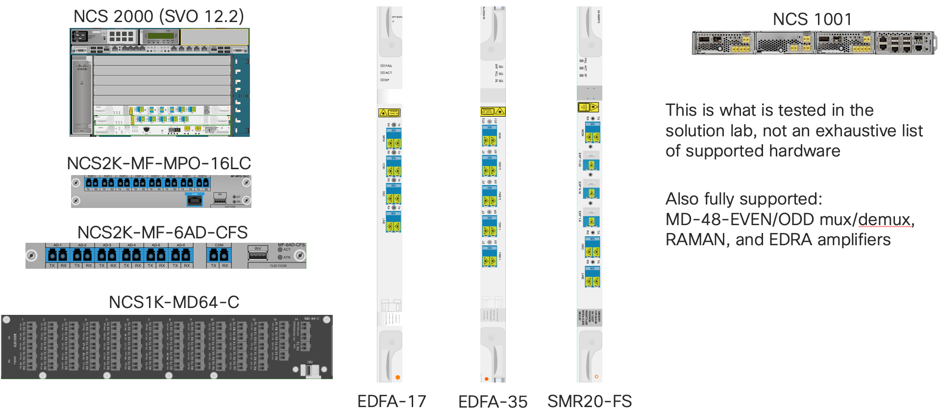
Network Convergence System 2000
The NCS 2000 Optical Line System is a flexible platform supporting all modern optical topologies and deployment use cases. Simple point to point to multi-degree CDC deployments are all supported as part of Routed Optical Networking.
See more information on the NCS 2000 series at https://www.cisco.com/c/en/us/products/optical-networking/network-convergence-system-2000-series/index.html
Network Convergence System 1000 Multiplexer
The NCS1K-MD-64-C is a new fixed multiplexer designed specifically for the 400G 75Ghz 400ZR and OpenZR+ wavelengths, allowing up to 25.6Tbps on a single fiber.
Network Convergence System 1001
The NCS 1001 is utiized in point to point network spans as an amplifier and optionally protection switch. The NCS 1001 now has specific support for 75Ghz spaced 400ZR and OpenZR+ wavelengths, with the ability to monitor incoming wavelengths for power. The 1001 features the ability to determine the proper amplifier gain setpoints based on the desired user power levels.
See more information on the NCS 1001 at https://www.cisco.com/c/en/us/products/collateral/optical-networking/network-convergence-system-1000-series/datasheet-c78-738782.html
Routed Optical Networking Automation
Overview
Routed Optical Networking by definition is a disaggregated optical solution, creating efficiency by moving coherent endpoints in the router. The solution requires a new way of managing the network, one which unifies the IP and Optical layers, replacing the traditional siloed tools used in the past. Real transformation in operations comes from unifying teams and workflows, rather than trying to make an existing tool fit a role it was not originally designed for. Cisco’s standards based hierarchical SDN solution allows providers to manage a multi-vendor Routed Optical Networking solution using standard interfaces and YANG models.
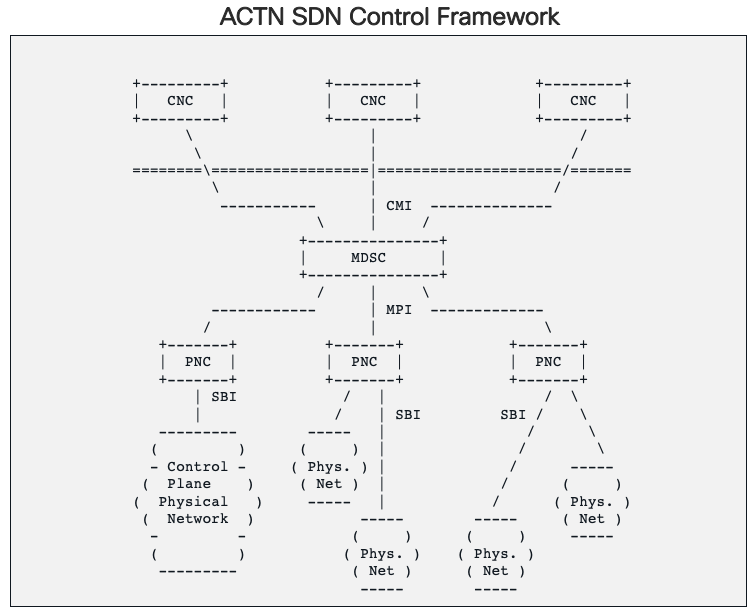
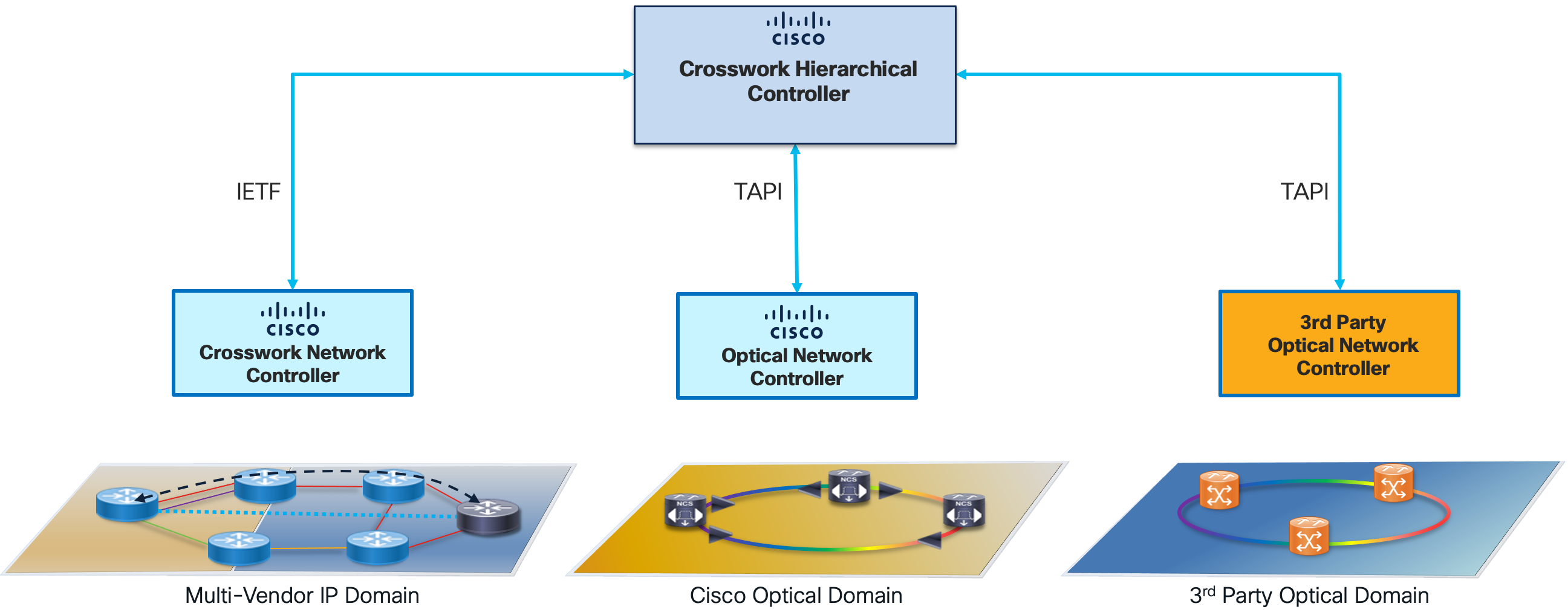
IETF ACTN SDN Framework
The IETF Action and Control of Traffic Engineered Networks group (ACTN) has defined a hierarchical controller framework to allow vendors to plug components into the framework as needed. The lowest level controller, the Provisioning Network Controller (PNC), is responsible for managing physical devices. These controller expose their resources through standard models and interface to a Hierarchical Controller (HCO), called a Multi-Domain Service Controller (MDSC) in the ACTN framework.
Note that while Cisco is adhering to the IETF framework proposed in RFC8453 , Cisco is supporting the most widely supported industry standards for controller to controller communication and service definition. In optical the de facto standard is Transport API from the ONF for the management of optical line system networks and optical services. In packet we are leveraging Openconfig device models where possible and IETF models for packet topology (RFC8345) and xVPN services (L2NM and L3NM)
Cisco’s SDN Controller Automation Stack
Aligning to the ACTN framework, Cisco’s automation stack includes a multi-vendor IP domain controller (PNC), optical domain controller (PNC), and multi-vendor hierarchical controller (HCO/MDSC).
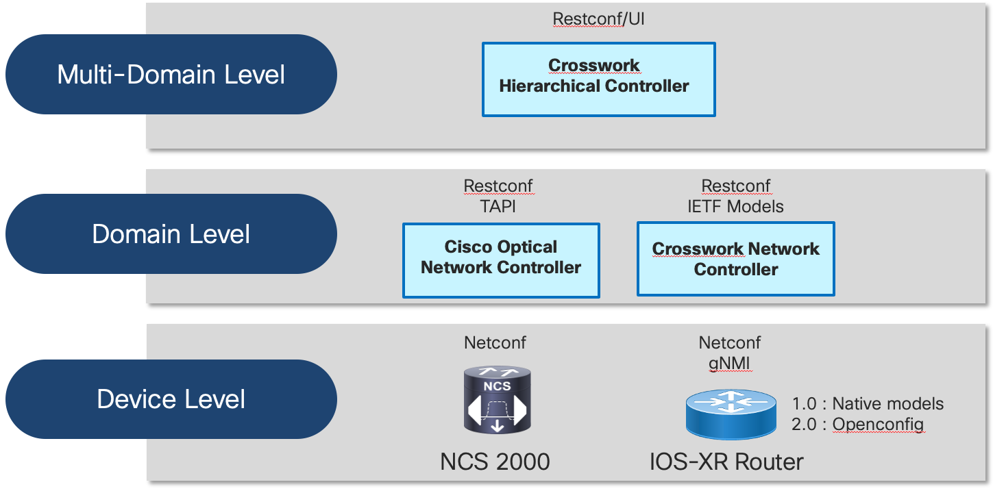
Cisco Open Automation
Cisco believes not all providers consume automation in the same way, so we are dedicated to make sure we have open interfaces at each layer of the network stack. At the device level, we utilize standard NETCONF, gRPC, and gNMI interfaces along with native, standard, and public consortium YANG models. There is no aspect of a Cisco IOS-XR router today not covered by YANG models. At the domain level we have Cisco’s network controllers, which use the same standard interfaces to communicate with devices and expose standards based NBIs. Our multi-layer/multi-domain controller likewise uses the same standard interfaces.
Crosswork Hierarchical Controller
Responsible for Multi-Layer Automation is the Crosswork Hierarchical Controller. Crosswork Hierarchical Controller is responsible for the following network functions:
- CW HCO unifies data from the IP and optical networks into a single network model. HCO utilizes industry standard IETF topology models for IP and TAPI for optical topology and service information. HCO can also leverage legacy EMS/NMS systems or device interrogation.
- Responsible for managing multi-layer Routed Optical Networking links using a single UI.
- Providing assurance at the IP and optical layers in a single tool. The network model allows users to quickly correlate faults and identify at which layer faults have occurred.
- Additional HCO applications include the Root Cause Analysis tool, able to quickly correlate upper layer faults to an underlying cause.
Please see the following resources for more information on Crosswork HCO. https://www.cisco.com/c/en/us/products/collateral/cloud-systems-management/crosswork-network-automation/solution-overview-c22-744695.html
Crosswork Network Controller
Crosswork Network Controller is a multi-vendor IP domain controller. Crosswork Network Controller is responsible for the following IP network functions.
- Collecting Ethernet, IP, RSVP-TE, and SR network information for internal applications and exposing northbound via IETF RFC 8345 topology models
- Collecting traffic information from the network for use with CNC’s traffic optimization application, Crosswork Optimization Engine
- Perform provisioning of SR-TE, RSVP-TE, L2VPN, and L3VPN using standard industry models (IETF TEAS-TE, L2NM, L3NM) via UI or northbound API
- Visualization and assurance of SR-TE, RSVP-TE, and xVPN services
- Use additional Crosswork applications to perform telemetry collection/alerting, zero-touch provisioning, and automated and assurance network changes
More information on Crosswork and Crosswork Network Controller can be found at https://www.cisco.com/c/en/us/products/collateral/cloud-systems-management/crosswork-network-automation/datasheet-c78-743456.html
Cisco Optical Network Controller
Cisco Optical Network Controller (Cisco ONC) is responsible for managing Cisco optical line systems and circuit services. Cisco ONC exposes a ONF TAPI northbound interface, the de facto industry standard for optical network management. Cisco ONC runs as an application on the same Crosswork Infrastructure as CNC.
More information on Cisco ONC can be found at https://www.cisco.com/c/en/us/support/optical-networking/optical-network-controller/series.html
Cisco Network Services Orchestrator and Routed Optical Networking ML Core Function Pack
Cisco NSO is the industry standard for service orchestration and device configuration management. The RON-ML CFP can be used to fully configure an IP link between routers utilizing 400ZR/OpenZR+ optics over a Cisco optical line system using Cisco ONC. This includes IP addressing and adding links to an existing Ethernet LAG. The CFP can also support optical-only provisioning on the router to fit into existing optical provisioning workflows.
Routed Optical Networking Service Management
Supported Provisioning Methods
We support multiple ways to provision Routed Optical Networking services based on existing provider workflows.
- Unified IP and Optical using Crosswork Hierarchical Controller
- Unified IP and Optical using Cisco NSO Routed Optical Networking Multi-Layer Function Pack
- ZR/ZR+ Optics using IOS-XR CLI
- ZR/ZR+ Optics using IOS-XR Netconf
OpenZR+ and 400ZR Properties
ZR/ZR+ Supported Frequencies
The frequency on Cisco ZR/ZR+ transceivers may be set between 191.275Thz and 196.125Thz in increments of 6.25Ghz, supporting flex spectrum applications. To maximize the available C-Band spectrum, these are the recommended 64 75Ghz-spaced channels, also aligning to the NCS1K-MD-64-C fixed channel add/drop multiplexer.
| 196.100 | 196.025 | 195.950 | 195.875 | 195.800 | 195.725 | 195.650 | 195.575 |
| 195.500 | 195.425 | 195.350 | 195.275 | 195.200 | 195.125 | 195.050 | 194.975 |
| 194.900 | 194.825 | 194.75 | 194.675 | 194.600 | 194.525 | 194.450 | 194.375 |
| 194.300 | 194.225 | 194.150 | 194.075 | 194.000 | 193.925 | 193.850 | 193.775 |
| 193.700 | 193.625 | 193.550 | 193.475 | 193.400 | 193.325 | 193.250 | 193.175 |
| 193.100 | 193.025 | 192.950 | 192.875 | 192.800 | 192.725 | 192.650 | 192.575 |
| 192.500 | 192.425 | 192.350 | 192.275 | 192.200 | 192.125 | 192.050 | 191.975 |
| 191.900 | 191.825 | 191.750 | 191.675 | 191.600 | 191.525 | 191.450 | 191.375 |
Supported Line Side Rate and Modulation
OIF 400ZR transceivers support 400G only per the OIF specification. OpenZR+ transceivers can support 100G, 200G, 300G, or 400G line side rate. See router platform documentation for supported rates. The modulation is determined by the line side rate. 400G will utilize 16QAM, 300G 8QAM, and 200G/100G rates will utilize QPSK.
Crosswork Hierarchical Controller UI Provisioning
End-to-End IP+Optical provisioning can be done using Crosswork Hierarchical Controller’s GUI IP Link provisioning. Those familiar with traditional GUI EMS/NMS systems for service management will have a very familiar experience. Crosswork Hierarchical Controller provisioning will provision both the router optics as well as the underlying optical network to support the ZR/ZR+ wavelength.
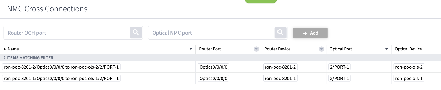
Inter-Layer Link Definition
End to end provisioning requires first defining the Inter-Layer link between the router ZR/ZR+ optics and the optical line system add/drop ports. This is done using a GUI based NMC (Network Media Channel) Cross-Link application in Crosswork HCO. The below screenshot shows defined NMC cross-links.
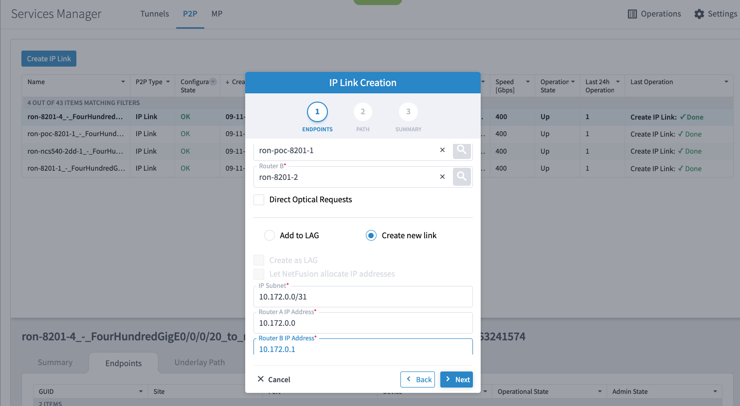
IP Link Provisioning
Once the inter-layer links are created, the user can then proceed in provisioning an end to end circuit. The provisioning UI takes as input the two router endpoints, the associated ZR/ZR+ ports, and the IP addressing or bundle membership of the link. The optical line system provisioning is abstracted from the user, simplifying the end to end workflow. The frequency and power is automatically derived by Cisco Optical Network Controller based on the add/drop port and returned as a parameter to be used in router optics provisioning.
Operational Discovery
The Crosswork Hierarchical Controller provisioning process also performs a discovery phase to ensure the service is operational before considering the provisioning complete. If operational discovery fails, the end to end service will be rolled back.
NSO RON-ML CFP Provisioning
Providers familiar with using Cisco Network Service Orchestrator have an option to utilize NSO to perform IP+Optical provisioning of Routed Optical Networking services. Cisco has created the Routed Optical Network Multi-Layer Core Function Pack, RON-ML CFP to perform end to end provisioning of services. The aforementioned Crosswork HCO provisioning utilizes the RON-ML CFP to perform end device provisioning.
Please see the Cisco Routed Optical Networking RON-ML CFP documentation located at
Routed Optical Networking Inter-Layer Links
Similar to the use case with CW HCO provisioning, before end to end provisioning can be performed, inter-layer links must be provisioned between the optical ZR/ZR+ port and the optical line system add/drop port. This is done using the “inter-layer-link” NSO service. The optical end point can be defined as either a TAPI SIP or by the TAPI equipment inventory identifier. Inter-layer links are not required for router-only provisioning.
RON-ML End to End Service
The RON-ML service is responsible for end to end IP+optical provisioning. RON-ML supports full end to end provisioning, router-only provisioning, or optical-only provisioning where only the router ZR/ZR+ configuration is performed. The frequency and transmit power can be manually defined or optionally provided by Cisco ONC when end to end provisioning is performed.
RON-ML API Provisioning
Use the following URL for NSO provisioning: http://<nso host>/restconf/data
Inter-Layer Link Service
{
  "data": {
    "cisco-ron-cfp:ron": {
      "inter-layer-link": [
        {
          "end-point-device": "ron-8201-1",
          "line-port": "0/0/0/20",
          "ols-domain": {
            "network-element": "ron-ols-1",
            "optical-add-drop": "1/2008/1/13,14",
            "optical-controller": "onc-real-new"
          }
        }
      ]
    }
  }
}
Provisioning ZR+ optics and adding interface to Bundle-Ether 100 interface
{
    "cisco-ron-cfp:ron": {
      "ron-ml": [
        {
          "name": "E2E_Bundle_ZRP_ONC57_2",
          "mode": "transponder",
          "bandwidth": "400",
          "circuit-id": "E2E Bundle ONC-57 S9|chan11 - S10|chan11",
          "grid-type": "100mhz-grid",
          "ols-domain": {
            "service-state": "UNLOCKED"
          },
          "end-point": [
            {
              "end-point-device": "ron-8201-1",
              "terminal-device-optical": {
                "line-port": "0/0/0/11",
                "transmit-power": -100
              },
              "ols-domain": {
                "end-point-state": "UNLOCKED"
              },
              "terminal-device-packet": {
                "bundle": [
                  {
                    "id": 100
                  }
                ],
                "interface": [
                  {
                    "index": 0,
                    "membership": {
                      "bundle-id": 100,
                      "mode": "active"
                    }
                  }
                ]
              }
            },
            {
              "end-point-device": "ron-8201-2",
              "terminal-device-optical": {
                "line-port": "0/0/0/11",
                "transmit-power": -100
              },
              "ols-domain": {
                "end-point-state": "UNLOCKED"
              },
              "terminal-device-packet": {
                "bundle": [
                  {
                    "id": 100
                  }
                ],
                "interface": [
                  {
                    "index": 0,
                    "membership": {
                      "bundle-id": 100,
                      "mode": "active"
                    }
                  }
                ]
              }
            }
          ]
        }
      ]
    }
  }
IOS-XR CLI Configuration
Configuring the router portion of the Routed Optical Networking link is very simple. All optical configuration related to the ZR/ZR+ optics configuration is located under the optics controller relevent to the faceplate port. Default configuration the optics will be in an up/up state using a frequency of 193.10Thz.
The basic configuration with a specific frequency of 195.65 Thz is located below,
the only required component is the bolded channel frequency setting.
ZR/ZR+ Optics Configuration
controller Optics0/0/0/20
 transmit-power -100
 dwdm-carrier 100MHz-grid frequency 1956500
 logging events link-status
IOS-XR NETCONF Configuration
All configuration performed in IOS-XR today can also be done using NETCONF/YANG. The following payload exhibits the models and configuration used to perform router optics provisioning. This is a more complete example showing the FEC, power, modulation, and line side rate (200G) configuration.
<data xmlns="urn:ietf:params:xml:ns:netconf:base:1.0">
 <interface-configurations xmlns="http://cisco.com/ns/yang/Cisco-IOS-XR-ifmgr-cfg">
 <interface-configuration>
 <active>act</active>
 <interface-name>Optics0/0/0/20</interface-name>
    <description> Managed by NSO .58, do not change manually</description>
 <optics xmlns="http://cisco.com/ns/yang/Cisco-IOS-XR-controller-optics-cfg">
  <optics-transmit-power>-100</optics-transmit-power>
  <optics-performance-monitoring>true</optics-performance-monitoring>
     <optics-modulation>16qam</optics-modulation>
 <optics-fec>fec-ofec</optics-fec>
 <optics-dwdm-carrier>
  <grid-type>100Mhz-grid</grid-type>
  <param-type>frequency</param-type>
   <param-value>1956500 </param-value>
  </optics-dwdm-carrier>
 </optics>
 <breakout xmlns="http://cisco.com/ns/yang/Cisco-IOS-XR-optics-driver-cfg">2x100</breakout>
 </interface-configuration>
</interface-configurations>
</data>
Routed Optical Networking Assurance
Crosswork Hierarchical Controller
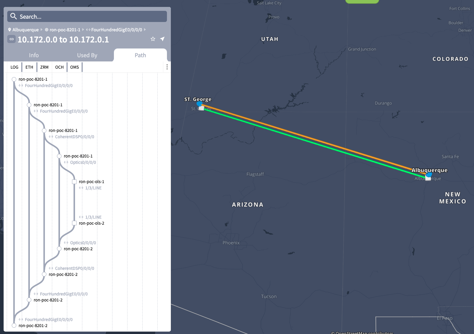
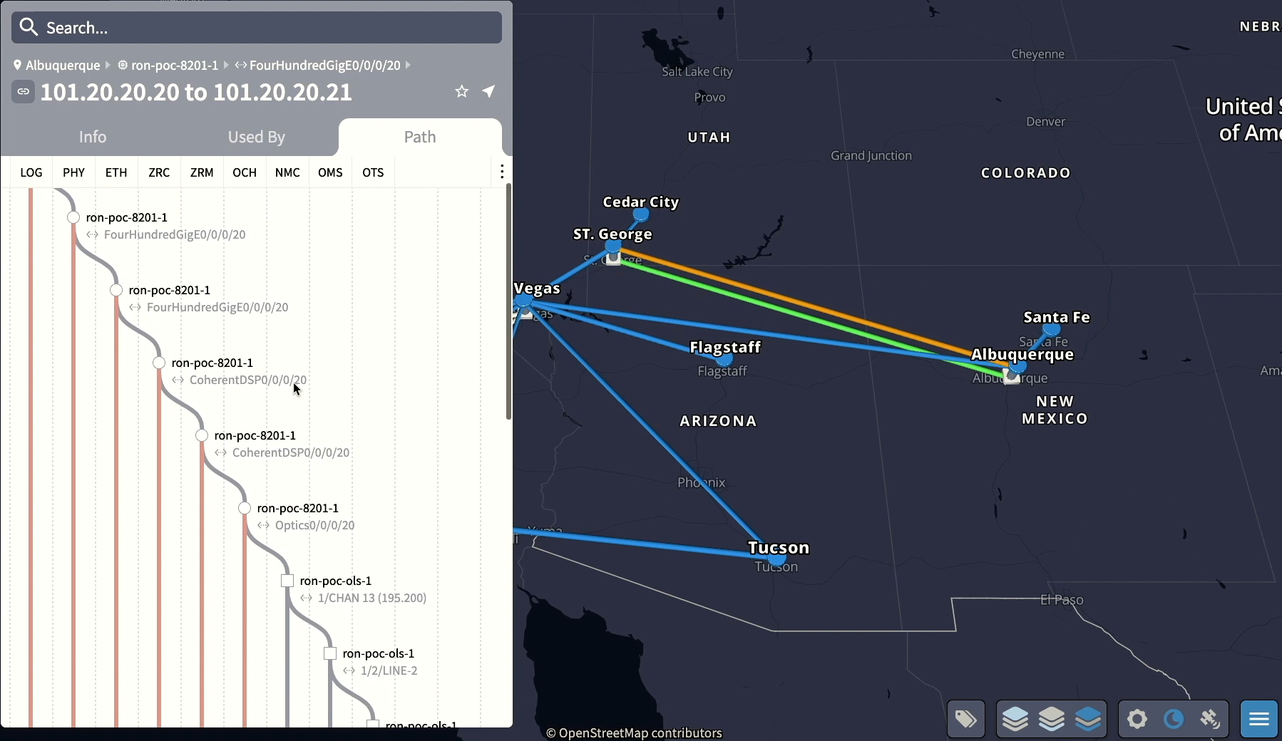
Multi-Layer Path Trace
Using topology and service data from both the IP and Optical network CW HCO can display the full service from IP services layer to the physical fiber. Below is an example of the “waterfall” trace view from the OTS (Fiber) layer to the Segment Routing TE layer across all layers. CW HCO identifies specific Routed Optical Networking links using ZR/ZR+ optics as seen by the ZRC (ZR Channel) and ZRM (ZR Media) layers from the 400ZR specification.
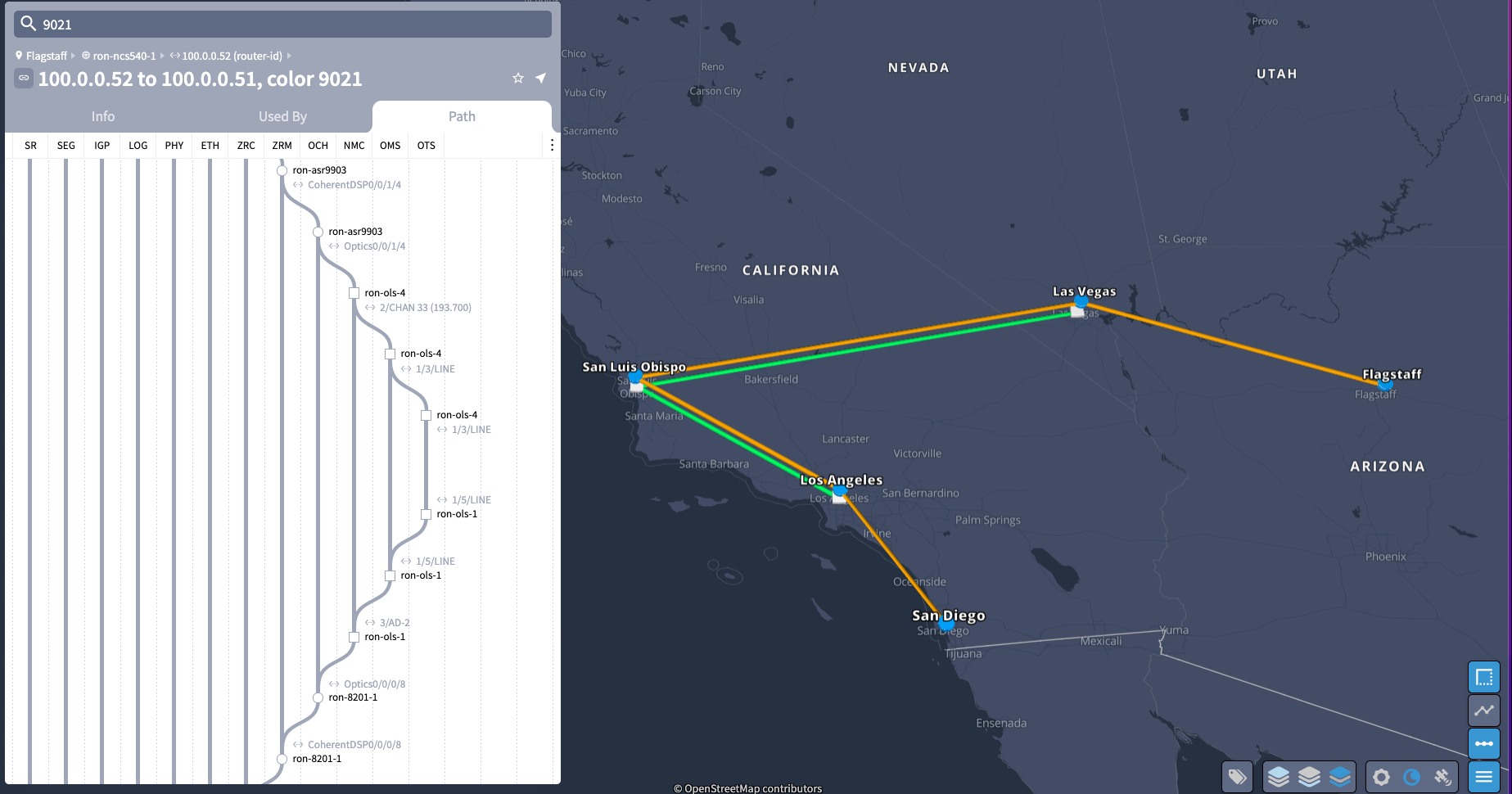
When faults occur at a specific layer, faults will be highlighted in red, quickly identifying the layer a fault has occurred.
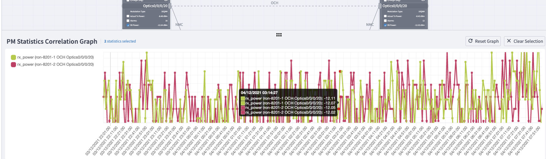
Routed Optical Networking Link Assurance
The Link Assurance application isolates the multi-layer path of a single Routed Optical Networking service, showing both the router termination points as well as the optical layer. This information is further enhanced with telemetry data coming from both the ZR/ZR+ optics as well as the optical link system nodes.
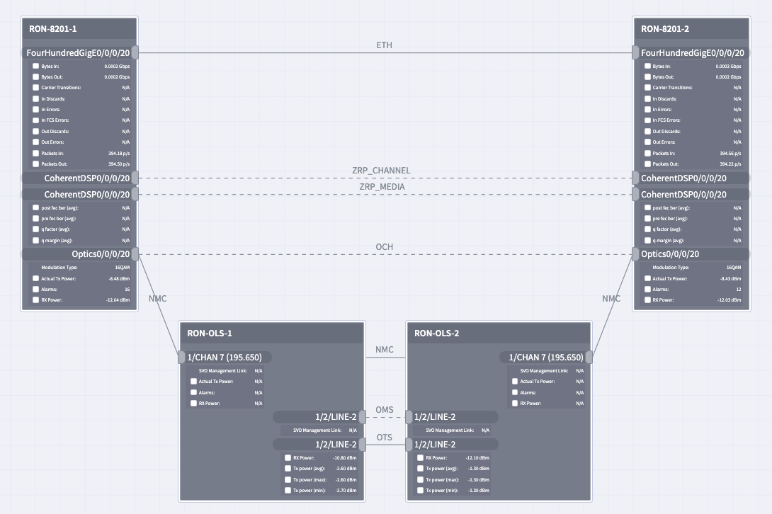
Optionally the user can see graphs of collected telemetry data to quickly identify trends or changes in specific operational data.
IOS-XR CLI Monitoring of ZR400/OpenZR+ Optics
Optics Controller
The optics controller represents the physical layer of the optics. In the case of ZR/ZR+ optics this includes the frequency information, RX/TX power, OSNR, and other associated physical layer information.
RP/0/RP0/CPU0:ron-8201-1#show controllers optics 0/0/0/20
Thu Jun  3 15:34:44.098 PDT

 Controller State: Up
 Transport Admin State: In Service
 Laser State: On
 LED State: Green
 FEC State: FEC ENABLED

 Optics Status

         Optics Type:  QSFPDD 400G ZR
         DWDM carrier Info: C BAND, MSA ITU Channel=10, Frequency=195.65THz,
         Wavelength=1532.290nm

         Alarm Status:
         -------------
         Detected Alarms: None

         LOS/LOL/Fault Status:

         Alarm Statistics:

         -------------
         HIGH-RX-PWR = 0            LOW-RX-PWR = 0
         HIGH-TX-PWR = 0            LOW-TX-PWR = 4
         HIGH-LBC = 0               HIGH-DGD = 1
         OOR-CD = 0                 OSNR = 10
         WVL-OOL = 0                MEA  = 0
         IMPROPER-REM = 0
         TX-POWER-PROV-MISMATCH = 0
         Actual TX Power = -7.17 dBm
         RX Power = -9.83 dBm
         RX Signal Power = -9.18 dBm
         Frequency Offset = 9 MHz
         Baud Rate =  59.8437500000 GBd
         Modulation Type: 16QAM
         Chromatic Dispersion 6 ps/nm
         Configured CD-MIN -2400 ps/nm  CD-MAX 2400 ps/nm
         Second Order Polarization Mode Dispersion = 34.00 ps^2
         Optical Signal to Noise Ratio = 35.50 dB
         Polarization Dependent Loss = 1.20 dB
         Polarization Change Rate = 0.00 rad/s
         Differential Group Delay = 2.00 ps
Performance Measurement Data
RP/0/RP0/CPU0:ron-8201-1#show controllers optics 0/0/0/20 pm current 30-sec optics 1
Thu Jun  3 15:39:40.428 PDT

Optics in the current interval [15:39:30 - 15:39:40 Thu Jun 3 2021]

Optics current bucket type : Valid
             MIN       AVG       MAX      Operational      Configured      TCA   Operational      Configured     TCA
                                          Threshold(min)   Threshold(min) (min) Threshold(max)   Threshold(max) (max)
LBC[% ]      : 0.0       0.0       0.0      0.0               NA              NO   100.0            NA              NO
OPT[dBm]     : -7.17     -7.17     -7.17    -15.09            NA              NO   0.00             NA              NO
OPR[dBm]     : -9.86     -9.86     -9.85    -30.00            NA              NO   8.00             NA              NO
CD[ps/nm]    : -489      -488      -488     -80000            NA              NO   80000            NA              NO
DGD[ps ]     : 1.00      1.50      2.00     0.00              NA              NO   80.00            NA              NO
SOPMD[ps^2]  : 28.00     38.80     49.00    0.00              NA              NO   2000.00          NA              NO
OSNR[dB]     : 34.90     35.12     35.40    0.00              NA              NO   40.00            NA              NO
PDL[dB]      : 0.70      0.71      0.80     0.00              NA              NO   7.00             NA              NO
PCR[rad/s]   : 0.00      0.00      0.00     0.00              NA              NO   2500000.00       NA              NO
RX_SIG[dBm]  : -9.23     -9.22     -9.21    -30.00            NA              NO   1.00             NA              NO
FREQ_OFF[Mhz]: -2        -1        4        -3600             NA              NO   3600             NA              NO
SNR[dB]      : 16.80     16.99     17.20    7.00              NA              NO   100.00           NA              NO
Coherent DSP Controller
The coherent DSP controller represents the framing layer of the optics. It includes Bit Error Rate, Q-Factor, and Q-Margin information.
RP/0/RP0/CPU0:ron-8201-1#show controllers coherentDSP 0/0/0/20
Sat Dec  4 17:24:38.245 PST

Port                                            : CoherentDSP 0/0/0/20
Controller State                                : Up
Inherited Secondary State                       : Normal
Configured Secondary State                      : Normal
Derived State                                   : In Service
Loopback mode                                   : None
BER Thresholds                                  : SF = 1.0E-5  SD = 1.0E-7
Performance Monitoring                          : Enable
Bandwidth                                       : 400.0Gb/s

Alarm Information:
LOS = 10        LOF = 0 LOM = 0
OOF = 0 OOM = 0 AIS = 0
IAE = 0 BIAE = 0        SF_BER = 0
SD_BER = 0      BDI = 0 TIM = 0
FECMISMATCH = 0 FEC-UNC = 0     FLEXO_GIDM = 0
FLEXO-MM = 0    FLEXO-LOM = 3   FLEXO-RDI = 0
FLEXO-LOF = 5
Detected Alarms                                 : None

Bit Error Rate Information
PREFEC  BER                                     : 1.7E-03
POSTFEC BER                                     : 0.0E+00
Q-Factor                                        : 9.30 dB
Q-Margin                                        : 2.10dB


FEC mode                                        : C_FEC
Performance Measurement Data
RP/0/RP0/CPU0:ron-8201-1#show controllers coherentDSP 0/0/0/20 pm current 30-sec fec
Thu Jun  3 15:42:28.510 PDT

g709 FEC in the current interval [15:42:00 - 15:42:28 Thu Jun 3 2021]

FEC current bucket type : Valid
    EC-BITS   : 20221314973             Threshold : 83203400000            TCA(enable)  : YES
    UC-WORDS  : 0                       Threshold : 5                      TCA(enable)  : YES

                                      MIN       AVG        MAX      Threshold      TCA     Threshold     TCA
                                                                       (min)     (enable)    (max)     (enable)
PreFEC BER                     :   1.5E-03   1.5E-03   1.6E-03         0E-15        NO       0E-15        NO
PostFEC BER                    :     0E-15     0E-15     0E-15         0E-15        NO       0E-15        NO
Q[dB]                          :      9.40      9.40      9.40          0.00        NO        0.00        NO
Q_Margin[dB]                   :      2.20      2.20      2.20          0.00        NO        0.00        NO
Cisco IOS-XR Model-Driven Telemetry for ZR/ZR+ Monitoring
All operational data on IOS-XR routers can be monitored using streaming telemetry based on YANG models. Routed Optical Networking is no different, so a wealth of information can be streamed from the routers in intervals as low as 5s.
The following represents a list of validated sensor paths useful for monitoring the DCO optics in IOS-XR and the data fields available within these sensor paths. Note PM fields also support 15m and 24h paths in addition to the 30s paths shown in the table below.
| Sensor Path | Fields |
|---|---|
| Cisco-IOS-XR-controller-optics-oper:optics-oper/optics-ports/optics-port/optics-info | alarm-detected, baud-rate, dwdm-carrier-frequency, controller-state, laser-state, optical-signal-to-noise-ratio, temperature, voltage |
| Cisco-IOS-XR-controller-optics-oper:optics-oper/optics-ports/optics-port/optics-lanes/optics-lane | receive-power, receive-signal-power, transmit-power |
| Cisco-IOS-XR-controller-otu-oper:otu/controllers/controller/info | bandwidth, ec-value, post-fec-ber, pre-fec-ber, qfactor, qmargin, uc |
| Cisco-IOS-XR-pmengine-oper:performance-management/optics/optics-ports/optics-port/optics-current/optics-second30/optics-second30-optics/optics-second30-optic | dd__average, dgd__average, opr__average, opt__average, osnr__average, pcr__average, pmd__average, rx-sig-pow__average, snr__average, sopmd__average |
| Cisco-IOS-XR-pmengine-oper:performance-management/otu/otu-ports/otu-port/otu-current/otu-second30/otu-second30fecs/otu-second30fec | ec-bits__data, post-fec-ber__average, pre-fec-ber__average, q__average, qmargin__average, uc-words__data |
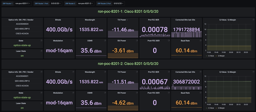
Open-source ZR/ZR+ Monitoring
Cisco model-driven telemetry along with the open source collector Telegraf and the open source dashboard software Grafana can be used to quickly build powerful dashboards to monitor ZR/ZR+ performance.
Additional Resources
Cisco Routed Optical Networking Home
- https://www.cisco.com/c/en/us/solutions/service-provider/routed-optical-networking.html
Cisco Routed Optical Networking Tech Field Day
- Solution Overview: https://techfieldday.com/video/build-your-network-with-cisco-routed-optical-networking-solution/
- Automation Demo: https://techfieldday.com/video/cisco-routed-optical-networking-solution-demo/
Cisco Champion Podcasts
- Cisco Routed Optical Networking Solution for the Next Decade https://smarturl.it/CCRS8E24
- Simplify Network Operations with Crosswork Hierarchical Controller: https://smarturl.it/CCRS8E48
Cisco Routed Optical Networking 1.0 Solution Guide
Appendix A
Acronyms
| DWDM | Dense Waveform Division Multiplexing |
| OADM | Optical Add Drop Multiplexer |
| FOADM | Fixed Optical Add Drop Multiplexer |
| ROADM | Reconfigurable Optical Add Drop Multiplexer |
| DCO | Digital Coherent Optics |
| FEC | Forward Error Correction |
| OSNR | Optical Signal to Noise Ratio |
| BER | Bit Error Rate |
DWDM Network Hardware Overview
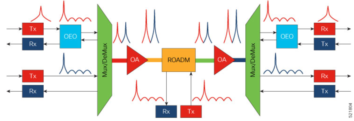
Optical Transmitters and Receivers
Optical transmitters provide the source signals carried across the DWDM network. They convert digital electrical signals into a photonic light stream on a specific wavelength. Optical receivers detect pulses of light and and convert signals back to electrical signals. In Routed Optical Networking, digital coherent QSFP-DD OpenZR+ and 400ZR transceivers in routers are used as optical transmitters and receivers.
Multiplexers/Demultiplexers
Multiplexers take multiple wavelengths on separate fibers and combine them into a single fiber. The output of a multiplexer is a composite signal. Demultiplexers take composite signals that compatible multiplexers generate and separate the individual wavelengths into individual fibers.
Optical Amplifiers
Optical amplifiers amplify an optical signal. Optical amplifiers increase the total power of the optical signal to enable the signal transmission across longer distances. Without amplifiers, the signal attenuation over longer distances makes it impossible to coherently receive signals. We use different types of optical amplifiers in optical networks. For example: preamplifiers, booster amplifiers, inline amplifiers, and optical line amplifiers.
Optical add/drop multiplexers (OADMs)
OADMs are devices capable of adding one or more DWDM channels into or dropping them from a fiber carrying multiple channels.
Reconfigurable optical add/drop multiplexers (ROADMs)
ROADMs are programmable versions of OADMs. With ROADMs, you can change the wavelengths that are added or dropped. ROADMs make optical networks flexible and easily modifiable.
Leave a Comment