Cisco SDN Controller Architecture
| Version | Date | Comments |
|---|---|---|
| 1.0 | 09/01/2022 | Initial Publication |
Software Defined Networking Overview
Software Defined Networking or "SDN" is the utilization of external software elements and APIs to manage physical network infrastructure and the services traversing the network. The external software elements continuously communicate with the network, consuming changes in topology, performance data, and fault information to enact intelligent network modifications.
A set of SDN applications used to mange a defined set of resources are combined in what is called a network "controller."
SDN Network Variations
Non-SDN Network
A network without SDN uses the traditional distributed control plane protocols to create network adjacencies and distribute IP routing information end to end across the network. At each node the routing information is used to create local forwarding entries. The logic used to program forwarding entries is based only on the information carried in the routing protocols. Most networks today fall under the umbrella of "non-SDN" networks.

SDN-Only Network
The physical separation of the network "control plane" and "data plane" was a key component of the original SDN definition. Proponents of SDN claimed it would help simplify the network infrastructure hardware, eschewing the distributed control plane and using a much simpler API to program hop by hop forwarding entries. Due to a variety of reasons, this purist view of SDN did not take hold in packet networks, however we do see instances today of SDN-only optical transport networks.
The other main component to any SDN network is the use of open APIs and programming interfaces, in the original SDN network that was a lower level API interface directly to the forwarding plane such as OpenFlow.

Hybrid SDN Network
Hybrid SDN represents a more pragmatic approach to SDN. Hybrid SDN adds intelligence to networks by augmenting the traditional distributed control plane with external software applications.
Open APIs are still critical in a hybrid SDN network, however instead of interfacing with the forwarding layer directly, SDN controllers may interface with higher layer control plane elements within the network infrastructure.
Intent Based Networking
Intent based networking often goes hand in hand with SDN. Intent based networking uses a declarative configuration model to define the end state of the network instead of building an explicit list of network instructions. The job of the SDN controller is to process the abstracted -state configuration and decompose it into the instructions required to achieve the end state.
An example of an intent based declarative configuration is "I need a low-latency EVPN-VPWS between endpoint A and endpoint Z." An IP layer controller may decompose this into the the following instructions:
- Provision low-latency SR-TE Policies PAZ and PZA between Node A, Node Z, if successful move to step 2.
- Dynamically allocate physical interface on Node A, Node Z
- Dynamically allocate EVPN EVI on Node A, Node Z
- Provision EVPN-VPWS on Node A, Node Z using SR-TE Policy PAZ and PZA.
- Enable proactive service assurance on EVPN-VPWS service
Key Drivers for SDN
Dynamic Network Programmability
Agility and flexibility are two tenets of a modern SDN network. SDN software allows operators to react to network changes such as traffic congestion quickly. Human intervention adds orders of magnitude of additional time in terms of MTTD (Mean Time to Detection) and MTTR (Mean Time To Repair).
Network Efficiency
Optimization of network resources is paramount for service providers today. Efficient networks are provisioned with the minimum amount of capacity to satisfy the bandwidth and resiliency requirements. Many networks today are over provisioned since they do not dynamically re-optimize network infrastructure and traffic.
Reducing the complexity of the network and overall TCO (Total Cost of Ownership) requires network planning and
Network Visibility and Assurance
Global view, data collection
Internet traffic has seen a compounded annual growth rate of 30- or higher over the last ten years, as more devices are connected, end user bandwidth speeds increase, and applications continue to move to the cloud. The introduction of 5G in mobile carriers and backhaul providers is also a disruptor, networks must be built to handle the advanced services and traffic increase associated with 5G. Networks must evolve so the infrastructure layer can keep up with the service layer. 400G Ethernet is the next evolution for SP IP network infrastructure, and we must make that as efficient as possible.
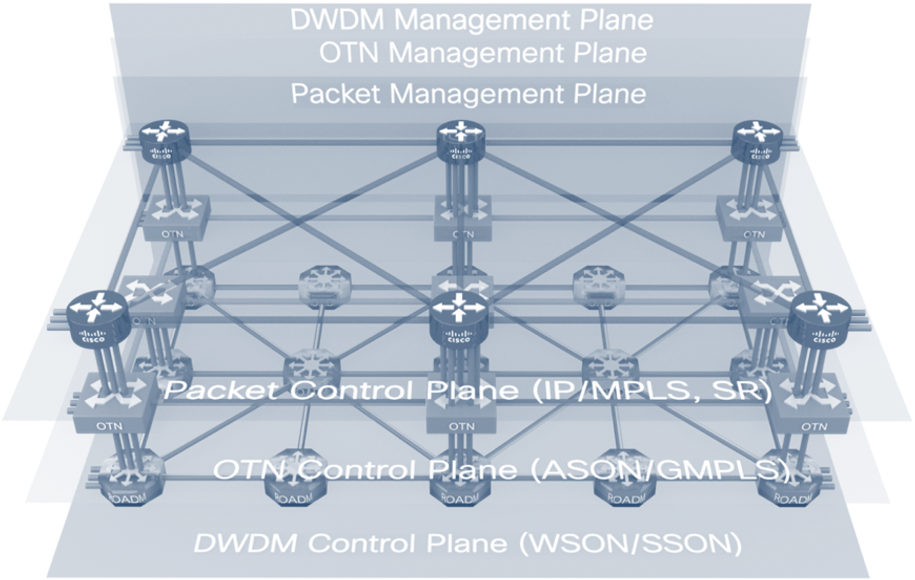
Network Complexity
Computer networks at their base are a set of interconnected nodes to deliver data between two endpoints. In the very beginning, these networks were designed using a layered approach to separate functions. The OSI model is an example of how functional separation has led to innovation by allowing different standards bodies to work in parallel at each layer. In some cases even these OSI layers are further split into different layers. While these layers can bring some cost benefit, it also brings added complexity. Each layer has its own management, control plane, planning, and operational model.
Components Required for SDN Control
Model-Driven Configuration
YANG (Yet Another Network Grammar) has emerged as the de-facto standard language used to describe network configuration. Device-level models are used to configure end devices, network models are used to describe higher layer network infrastructure, and service models are used to standardize how common network services are defined. Standardized models should be use wherever possible to enable multi-vendor controller to controller and controller to device communication.
Network Data Collection
The key to adding intelligence to the physical network is data. The source of the data can be from the network itself, from probes external to the network, or from completely external data sources containing information that can be used to make more intelligent routing decisions. As an example, application layer health can be used to effect underlay network routing.
Industry Initiatives
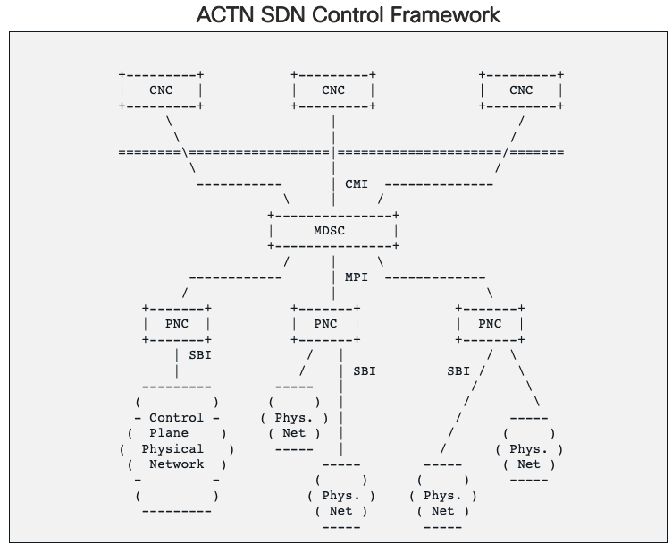
IETF ACTN SDN Framework
The IETF Action and Control of Traffic Engineered Networks group (ACTN) has defined a hierarchical controller framework to allow vendors to plug components into the framework as needed. The lowest level controller, the Provisioning Network Controller (PNC), is responsible for managing physical devices. These controller expose their resources through standard models and interface to a Hierarchical Controller (HCO), called a Multi-Domain Service Controller (MDSC) in the ACTN framework.
Note that while Cisco is adhering to the IETF framework proposed in RFC8453 , Cisco is supporting the most widely supported industry standards for controller to controller communication and service definition. In optical the de facto standard is Transport API from the ONF for the management of optical line system networks and optical services. In packet we are leveraging Openconfig device models where possible and IETF models for packet topology (RFC8345) and xVPN services (L2NM and L3NM)
Open Networking Foundation - Telecom Infra Project
Today's Complex Multi-Layer Network Infrastructure
Cisco's SDN Controller Automation Stack
Aligning to the ACTN framework, Cisco's automation stack includes a multi-vendor IP domain controller (PNC), optical domain controller (PNC), and multi-vendor hierarchical controller (HCO/MDSC).
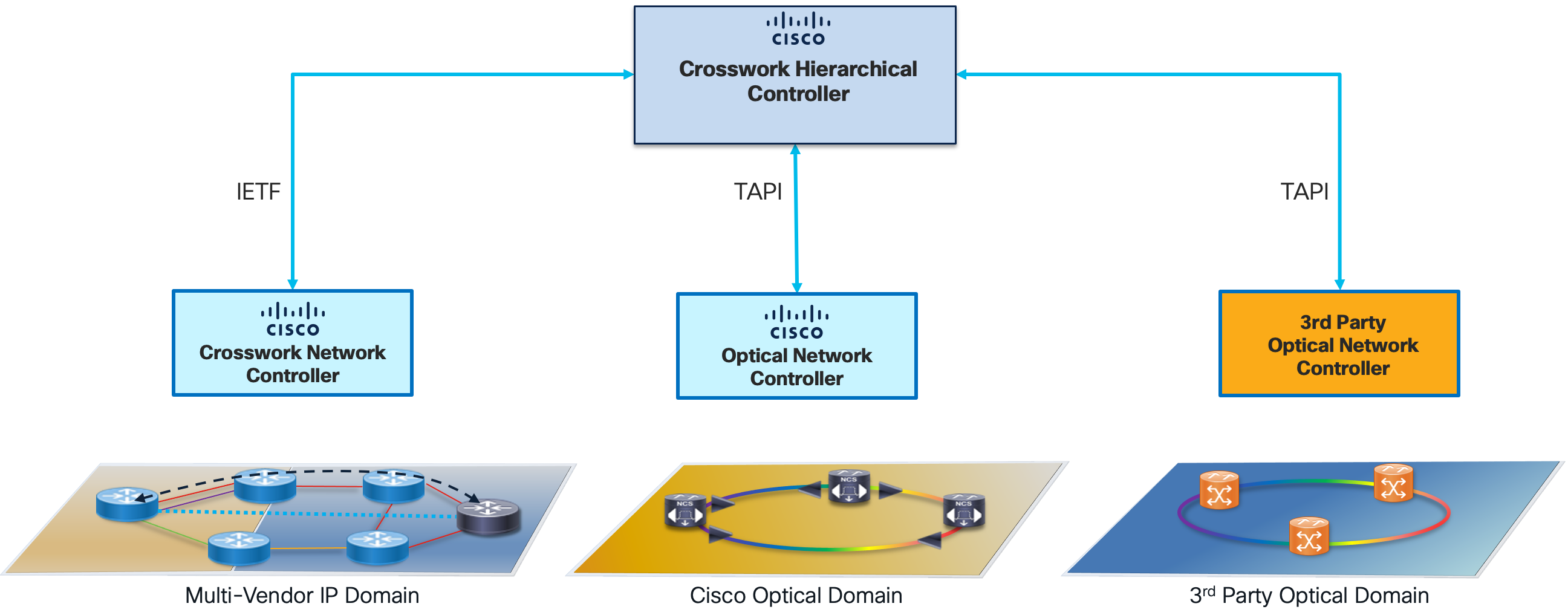
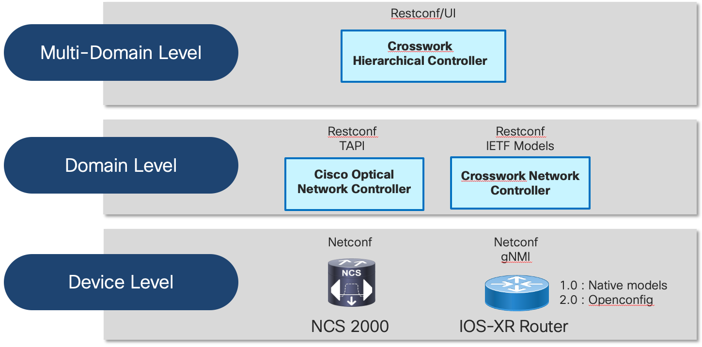
Cisco believes not all providers consume automation in the same way, so we are dedicated to make sure we have open interfaces at each layer of the network stack. At the device level, we utilize standard NETCONF, gRPC, and gNMI interfaces along with native, standard, and public consortium YANG models. There is no aspect of a Cisco IOS-XR router today not covered by YANG models. At the domain level we have Cisco's network controllers, which use the same standard interfaces to communicate with devices and expose standards based NBIs. Our multi-layer/multi-domain controller likewise uses the same standard interfaces.
Crosswork Hierarchical Controller
Responsible for Multi-Layer Automation is the Crosswork Hierarchical Controller. Crosswork Hierarchical Controller is responsible for the following network functions:
- CW HCO unifies data from the IP and optical networks into a single network model. HCO utilizes industry standard IETF topology models for IP and TAPI for optical topology and service information. HCO can also leverage legacy EMS/NMS systems or device interrogation.
- Responsible for managing multi-layer Routed Optical Networking links using a single UI.
- Providing assurance at the IP and optical layers in a single tool. The network model allows users to quickly correlate faults and identify at which layer faults have occurred.
- Additional HCO applications include the Root Cause Analysis tool, able to quickly correlate upper layer faults to an underlying cause.
Please see the following resources for more information on Crosswork HCO. https://www.cisco.com/c/en/us/products/collateral/cloud-systems-management/crosswork-network-automation/solution-overview-c22-744695.html
Crosswork Network Controller
Crosswork Network Controller is a multi-vendor IP domain controller. Crosswork Network Controller is responsible for the following IP network functions.
- Collecting Ethernet, IP, RSVP-TE, and SR network information for internal applications and exposing northbound via IETF RFC 8345 topology models
- Collecting traffic information from the network for use with CNC's traffic optimization application, Crosswork Optimization Engine
- Perform provisioning of SR-TE, RSVP-TE, L2VPN, and L3VPN using standard industry models (IETF TEAS-TE, L2NM, L3NM) via UI or northbound API
- Visualization and assurance of SR-TE, RSVP-TE, and xVPN services
- Use additional Crosswork applications to perform telemetry collection/alerting, zero-touch provisioning, and automated and assurance network changes
More information on Crosswork and Crosswork Network Controller can be found at https://www.cisco.com/c/en/us/products/collateral/cloud-systems-management/crosswork-network-automation/datasheet-c78-743456.html
Cisco Optical Network Controller
Cisco Optical Network Controller (Cisco ONC) is responsible for managing Cisco optical line systems and circuit services. Cisco ONC exposes a ONF TAPI northbound interface, the de facto industry standard for optical network management. Cisco ONC runs as an application on the same Crosswork Infrastructure as CNC.
More information on Cisco ONC can be found at https://www.cisco.com/c/en/us/support/optical-networking/optical-network-controller/series.html
Cisco Network Services Orchestrator and Routed Optical Networking ML Core Function Pack
Cisco NSO is the industry standard for service orchestration and device configuration management. The RON-ML CFP can be used to fully configure an IP link between routers utilizing 400ZR/OpenZR+ optics over a Cisco optical line system using Cisco ONC. This includes IP addressing and adding links to an existing Ethernet LAG. The CFP can also support optical-only provisioning on the router to fit into existing optical provisioning workflows.
Routed Optical Networking Service Management
Routed Optical Networking Assurance
Crosswork Hierarchical Controller
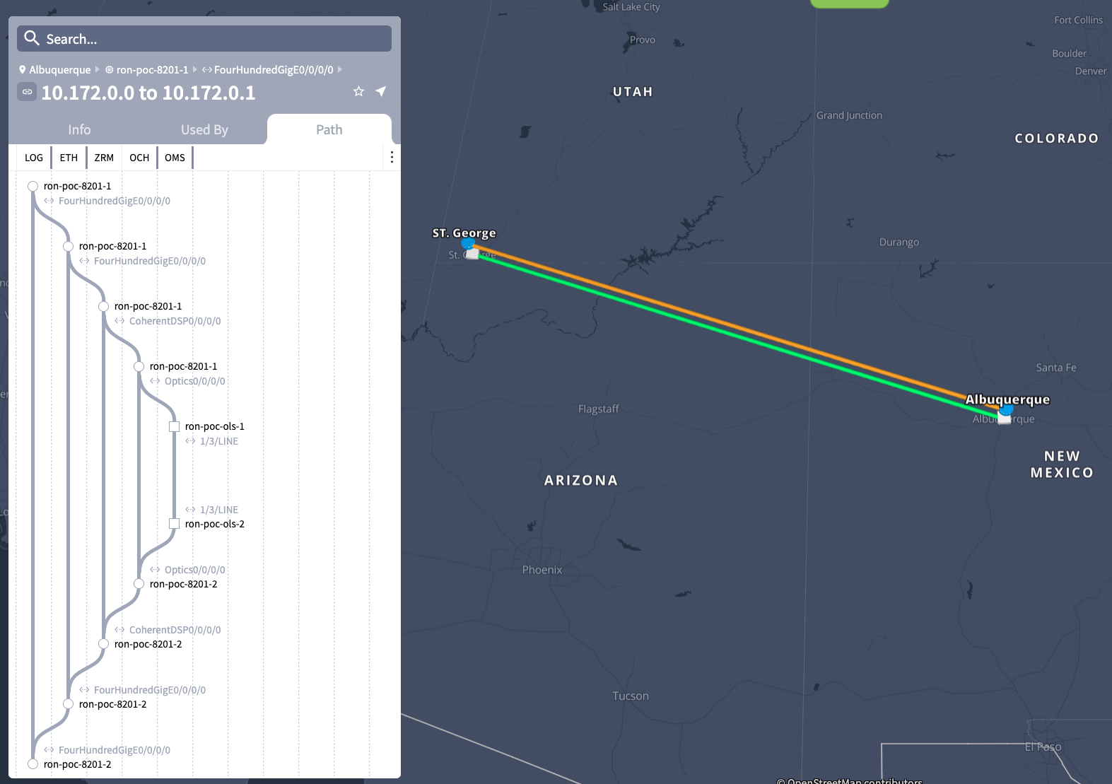
Multi-Layer Path Trace
Using topology and service data from both the IP and Optical network CW HCO can display the full service from IP services layer to the physical fiber. Below is an example of the "waterfall" trace view from the OTS (Fiber) layer to the Segment Routing TE layer across all layers. CW HCO identifies specific Routed Optical Networking links using ZR/ZR+ optics as seen by the ZRC (ZR Channel) and ZRM (ZR Media) layers from the 400ZR specification.

When faults occur at a specific layer, faults will be highlighted in red, quickly identifying the layer a fault has occurred.
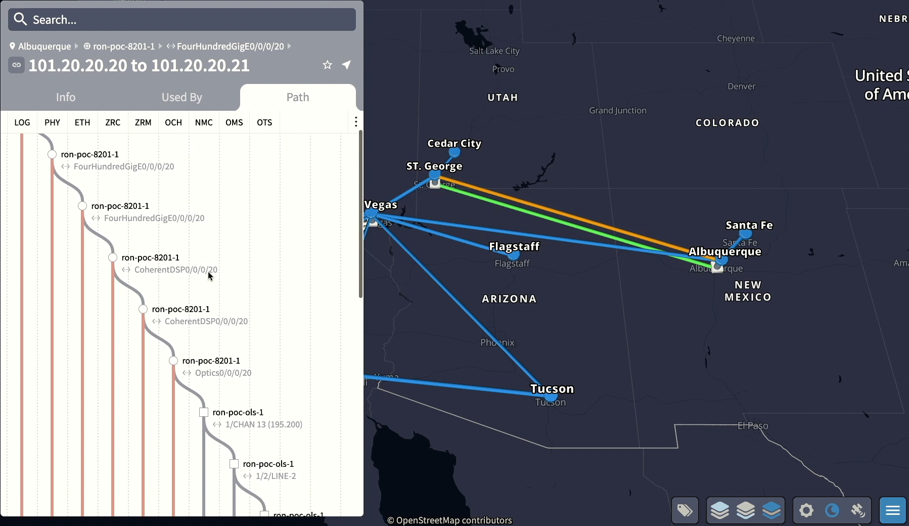
Routed Optical Networking Link Assurance
The Link Assurance application isolates the multi-layer path of a single Routed Optical Networking service, showing both the router termination points as well as the optical layer. This information is further enhanced with telemetry data coming from both the ZR/ZR+ optics as well as the optical link system nodes.
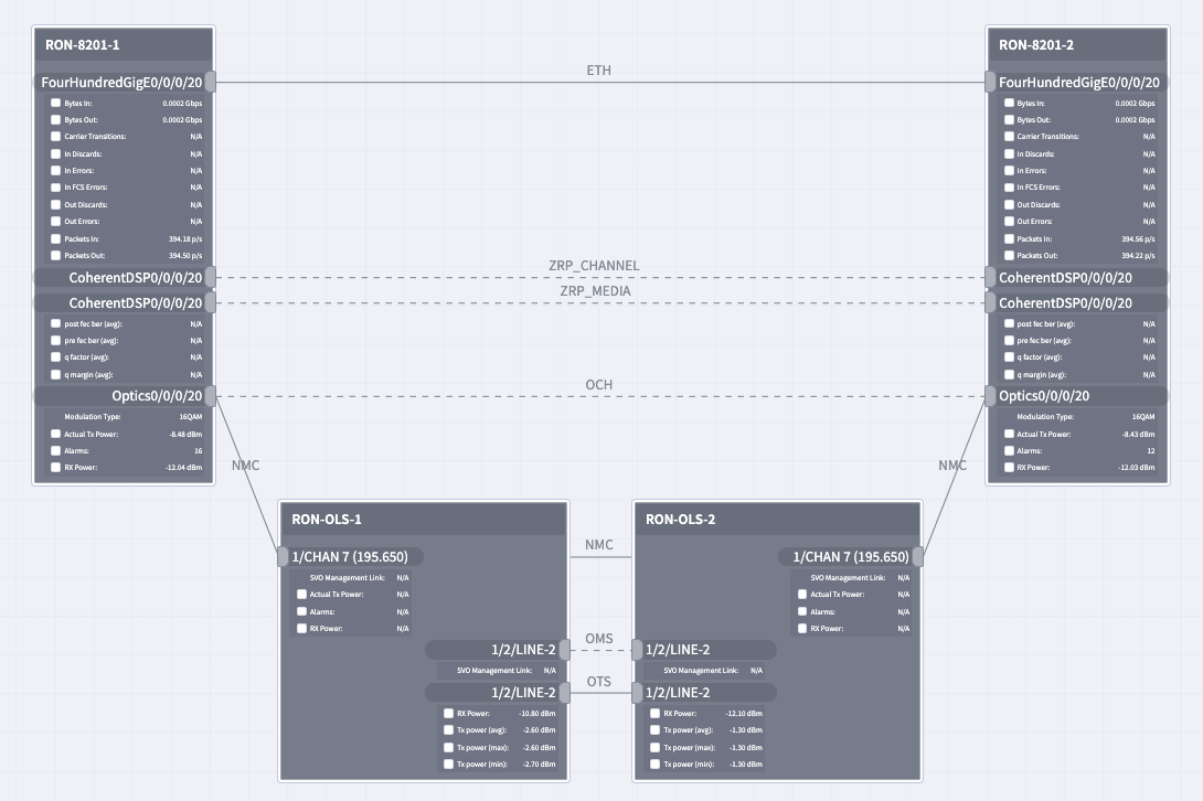
Optionally the user can see graphs of collected telemetry data to quickly identify trends or changes in specific operational
data.
tu-current/otu-second30/otu-second30fecs/otu-second30fec|ec-bits__data, post-fec-ber__average, pre-fec-ber__average, q__average, qmargin__average, uc-words__data |
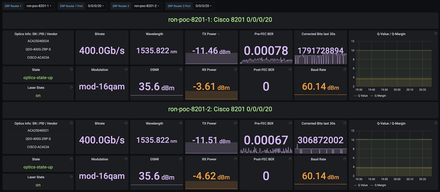
Open-source ZR/ZR+ Monitoring
Cisco model-driven telemetry along with the open source collector Telegraf and the open source dashboard software Grafana can be used to quickly build powerful dashboards to monitor ZR/ZR+ performance.
Additional Resources
Cisco Routed Optical Networking Home
Cisco Routed Optical Networking Tech Field Day
- Solution Overview: https://techfieldday.com/video/build-your-network-with-cisco-routed-optical-networking-solution/
- Automation Demo: https://techfieldday.com/video/cisco-routed-optical-networking-solution-demo/
Cisco Champion Podcasts
- Cisco Routed Optical Networking Solution for the Next Decade https://smarturl.it/CCRS8E24
- Simplify Network Operations with Crosswork Hierarchical Controller: <https://smarturl.it/CCRS8E48 >
Cisco Routed Optical Networking 1.0 Solution Guide
Appendix A
Acronyms
| DWDM | Dense Waveform Division Multiplexing |
| OADM | Optical Add Drop Multiplexer |
| FOADM | Fixed Optical Add Drop Multiplexer |
| ROADM | Reconfigurable Optical Add Drop Multiplexer |
| DCO | Digital Coherent Optics |
| FEC | Forward Error Correction |
| OSNR | Optical Signal to Noise Ratio |
| BER | Bit Error Rate |