
Converged SDN Transport Implementation Guide
Version
The following aligns to and uses features from Converged SDN Transport 5.0, please see the overview High Level Design document at https://xrdocs.io/design/blogs/latest-converged-sdn-transport-hld
Targets
-
Hardware:
- ASR 9000 as Centralized Provider Edge (C-PE) router
- NCS 5500, NCS 560, and NCS 55A2 as Aggregation and Pre-Aggregation router
- NCS 5500 as P core router
- ASR 920, NCS 540, and NCS 5500 as Access Provider Edge (A-PE)
- cBR-8 CMTS with 8x10GE DPIC for Remote PHY
- Compact Remote PHY shelf with three 1x2 Remote PHY Devices (RPD)
-
Software:
- IOS-XR 7.5.2 on Cisco 8000, NCS 560, NCS 540, NCS 5500, and NCS 55A2 routers
- IOS-XR 7.5.2 on ASR 9000 routers for non-cnBNG use
- IOS-XR 7.4.2 on ASR 9000 routers for cnBNG use
- IOS-XE 16.12.03 on ASR 920
- IOS-XE 17.03.01w on cBR-8
-
Key technologies
- Transport: End-To-End Segment-Routing
- Network Programmability: SR-TE Inter-Domain LSPs with On-Demand Next Hop
- Network Availability: TI-LFA/Anycast-SID
- Services: BGP-based L2 and L3 Virtual Private Network services (EVPN and L3VPN/mVPN)
- Network Timing: G.8275.1 and G.8275.2
- Network Assurance: 802.1ag
Testbed Overview
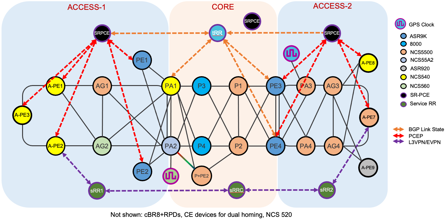
Devices
Access PE (A-PE) Routers
- Cisco NCS-5501-SE (IOS-XR) – A-PE7
- Cisco N540-24Z8Q2C-M (IOS-XR) - A-PE1, A-PE2, A-PE3
- Cisco N540-FH-CSR-SYS - A-PE8
- Cisco ASR-920 (IOS-XE) – A-PE9
Pre-Aggregation (PA) Routers
- Cisco NCS5501-SE (IOS-XR) – PA3, PA4
Aggregation (AG) Routers
- Cisco NCS5501-SE (IOS-XR) – AG2, AG3, AG4
- Cisco NCS 560-4 w/RSP-4E (IOS-XR) - AG1
High-scale Provider Edge Routers
- Cisco ASR9000 w/Tomahawk Line Cards (IOS-XR) – PE1, PE2
- Cisco ASR9000 w/Tomahawk and Lightspeed+ Line Cards (IOS-XR) – PE3, PE4
Area Border Routers (ABRs)
- Cisco ASR9000 (IOS-XR) – PE3, PE4
- Cisco 55A2-MOD-SE - PA2
- Cisco NCS540 - PA1
Core Routers
- Cisco 55A1-36H (36x100G) - P1,P2
- Cisco 8201-32FH - P3,P4
Service and Transport Route Reflectors (RRs)
- Cisco IOS XRv 9000 – tRR1-A, tRR1-B, sRR1-A, sRR1-B, sRR2-A, sRR2-B, sRR3-A, sRR3-B
Segment Routing Path Computation Element (SR-PCE)
- Cisco IOS XRv 9000 – SRPCE-A1-A, SRPCE-A1-B, SRPCE-A2-A, SRPCE-A2-A, SRPCE-CORE-A, SRPCE-CORE-B
Key Resources to Allocate
- IP Addressing
- IPv4 address plan
- IPv6 address plan, recommend dual plane day 1
- Plan for SRv6 in the future
- Color communities for ODN
- Segment Routing Blocks
- SRGB (segment-routing address block)
- Keep in mind anycast SID for ABR node pairs
- Allocate 3 SIDs for potential future Flex-algo use
- SRLB (segment routing local block)
- Local significance only
- Can be quite small and re-used on each node
- IS-IS unique instance identifiers for each domain
Role-Based Router Configuration
IOS-XR Router Configuration
Underlay Bundle interface configuration with BFD
interface Bundle-Ether100
 bfd mode ietf
 bfd address-family ipv4 timers start 180
 bfd address-family ipv4 multiplier 3
 bfd address-family ipv4 destination 10.1.2.1
 bfd address-family ipv4 fast-detect
 bfd address-family ipv4 minimum-interval 50
 mtu 9216
 ipv4 address 10.15.150.1 255.255.255.254
 ipv4 unreachables disable
 load-interval 30
 dampening
Underlay physical interface configuration
interface HundredGigE0/0/0/24
 mtu 9216
 ipv4 address 10.15.150.1 255.255.255.254
 ipv4 unreachables disable
 load-interval 30
 dampening
Performance Measurement
Interface delay metric dynamic configuration
Starting with CST 3.5 we now support end to end dynamic link delay measurements across all IOS-XR nodes. The feature in IOS-XR is called Performance Measurement and all configuration is found under the performance-measurement configuration hierarchy. There are a number of configuration options utilized when configuring performance measurement, but the below configuration will enable one-way delay measurements on physical links. The probe measurement-mode options are either one-way or two-way. One-way mode requires nodes be time synchronized to a common PTP clock, and should be used if available. In the absence of a common PTP clock source, two-way mode can be used which calculates the one-way delay using multiple timestamps at the querier and responder.
The advertisement options specify when the advertisements are made into the IGP. The periodic interval sets the minimum interval, with the threshold setting the difference required to advertise a new delay value. The accelerated threshold option sets a percentage change required to trigger and advertisement prior to the periodic interval timer expiring. Performance measurement takes a series of measurements within each computation interval and uses this information to derive the min, max, and average link delay.
Full documentation on Performance Measurement can be found at: https://www.cisco.com/c/en/us/td/docs/routers/asr9000/software/asr9k-r7-5/segment-routing/configuration/guide/b-segment-routing-cg-asr9000-75x/configure-performance-measurement.html
performance-measurement
 interface TenGigE0/0/0/20
  delay-measurement
  !
 !
 interface TenGigE0/0/0/21
  delay-measurement
  !
 !
 protocol twamp-light
  measurement delay
   unauthenticated
    querier-dst-port 12345
   !
  !
 !
 delay-profile interfaces
  advertisement
   accelerated
    threshold 25
   !
   periodic
    interval 120
    threshold 10
   !
  !
  probe
   measurement-mode two-way
   protocol twamp-light
   computation-interval 60
  !
 !
!
end
Interface delay metric static configuration
In the absence of dynamic realtime one-way latency monitoring for physical interfaces, the interface delay can be set manually. The one-way delay measurement value is used when computing SR Policy paths with the “latency” constraint type. The configured value is advertised in the IGP using extensions defined in RFC 7810, and advertised to the PCE using BGP-LS extensions. Keep in mind the delay metric value is defined in microseconds, so if you are mixing dynamic computation with static values they should be set appropriately.
performance-measurement
 interface TenGigE0/0/0/10
  delay-measurement
   advertise-delay 15000
 interface TenGigE0/0/0/20
  delay-measurement
   advertise-delay 10000
SR Policy Delay Measurement Profile
Properties for SR Policy end to end measurement can be customized to set specific intervals, logging, delay thresholds, and protocol. The “default” profile will be used for all SR Policies with delay measurement enabled unless a specific profile is specified.
delay-profile sr-policy default
  advertisement
   accelerated
    threshold 25
   !
   periodic
    interval 120
    threshold 10
   !
   threshold-check
    average-delay
   !
  !
  probe
   tos
    dscp 46
   !
   measurement-mode two-way
   protocol twamp-light
   computation-interval 60
   burst-interval 60
  !
 !
 protocol twamp-light
  measurement delay
   unauthenticated
    querier-dst-port 12345
Enabling SR Policy Delay Measurement
policy srte_c_5227_ep_100.0.0.27
   color 5227 end-point ipv4 100.0.0.27
   candidate-paths
    preference 100
     dynamic
      metric
       type igp
      !
     !
    !
   !
   performance-measurement
    delay-measurement
SR Policy Liveness Detection Profile
Note on platforms with HW enabled probe generation, the minimum interval is 3.3ms, on platforms with CPU probe generation, the minimum interval is 30ms (30000us).
performance-measurement
 liveness-profile name cst
  liveness-detection
   multiplier 3
  !
  probe
   tx-interval 30000
SR Policy with Liveness Detection Enabled
This example uses the default liveness detection profile. In this case when three probes are missed, the SR Policy will transition to a “down” state due to the “invalidation-action down” command. If this is omitted, path changes will be logged but no action will be taken.
segment-routing
 traffic-eng
  policy sr-policy-liveness
   color 5000 end-point ipv4 100.0.0.25
   candidate-paths
    preference 200
     dynamic
      pcep
      !
      anycast-sid-inclusion
      !
     !
     constraints
      segments
       sid-algorithm 130
      !
     !
    !
   !
   performance-measurement
    liveness-detection
     invalidation-action down
IOS-XR SR-MPLS Transport
Segment Routing SRGB and SRLB Definition
It’s recommended to first configure the Segment Routing Global Block (SRGB) across all nodes needing connectivity between each other. In most instances a single SRGB will be used across the entire network. In a SR MPLS deployment the SRGB and SRLB correspond to the label blocks allocated to SR. IOS-XR has a maximum configurable SRGB limit of 512,000 labels, however please consult platform-specific documentation for maximum values. The SRLB corresponds to the labels allocated for SIDs local to the node, such as Adjacency-SIDs. It is recommended to configure the same SRLB block across all nodes. The SRLB must not overlap with the SRGB. The SRGB and SRLB are configured in IOS-XR with the following configuration:
segment-routing
 global-block 16000 23999
 local-block 15000 15999
IGP protocol (ISIS) and Segment Routing MPLS configuration
The following section documents the configuration without Flex-Algo, Flex-Algo configuration is found in the Flex-Algo configuration section.
Key chain global configuration for IS-IS authentication
key chain ISIS-KEY
 key 1
 accept-lifetime 00:00:00 january 01 2018 infinite
 key-string password 00071A150754
 send-lifetime 00:00:00 january 01 2018 infinite
 cryptographic-algorithm HMAC-MD5
IS-IS router configuration
All routers, except Area Border Routers (ABRs), are part of one IGP domain and L2 area (ISIS-ACCESS or ISIS-CORE). Area border routers
run two IGP IS-IS processes (ISIS-ACCESS and ISIS-CORE). Note that Loopback0 is part of both IGP processes.
router isis ISIS-ACCESS
 set-overload-bit on-startup 360
 is-type level-2-only
 net 49.0001.0101.0000.0110.00
 nsr
 distribute link-state
 nsf cisco
 log adjacency changes
 lsp-gen-interval maximum-wait 5000 initial-wait 5 secondary-wait 100
 lsp-refresh-interval 65000
 max-lsp-lifetime 65535
 lsp-password keychain ISIS-KEY
 address-family ipv4 unicast
  metric-style wide
  advertise link attributes
  spf-interval maximum-wait 1000 initial-wait 5 secondary-wait 100
  segment-routing mpls
  spf prefix-priority high tag 1000
  maximum-redistributed-prefixes 100 level 2
 !
 address-family ipv6 unicast
  metric-style wide
  spf-interval maximum-wait 5000 initial-wait 50 secondary-wait 200
  maximum-redistributed-prefixes 100 level 2
Note: ABR Loopback 0 on domain boundary is part of both IGP processes together with same “prefix-sid absolute” value
Note: The prefix SID can be configured as either absolute or index. The index configuration is required for interop with nodes using a different SRGB.
IS-IS Loopback and node SID configuration
 interface Loopback0
  ipv4 address 100.0.1.50 255.255.255.255
  address-family ipv4 unicast
   prefix-sid absolute 16150
   tag 1000
IS-IS Physical and Bundle interface configuration with BFD
interface HundredGigE0/0/0/20/0
  circuit-type level-2-only
  bfd minimum-interval 5
  bfd multiplier 5
  bfd fast-detect ipv4
  point-to-point
  address-family ipv4 unicast
   fast-reroute per-prefix
   fast-reroute per-prefix ti-lfa
   metric 10
MPLS-TE Configuration
Enabling the use of Segment Routing Traffic Engineering requires first configuring basic MPLS TE so the router Traffic Engineering Database (TED) is populated with the proper TE attributes. The configuration requires no
mpls traffic-eng
Unnumbered Interfaces
IS-IS and Segment Routing/SR-TE utilized in the Converged SDN Transport design supports using unnumbered interfaces. SR-PCE used to compute inter-domain SR-TE paths also supports the use of unnumbered interfaces. In the topology database each interface is uniquely identified by a combination of router ID and SNMP IfIndex value.
Unnumbered interface configuration
interface TenGigE0/0/0/2
 description to-AG2
 mtu 9216
 ptp
  profile My-Slave
  port state slave-only
  local-priority 10
 !
 service-policy input core-ingress-classifier
 service-policy output core-egress-exp-marking
 ipv4 point-to-point
 ipv4 unnumbered Loopback0
 frequency synchronization
  selection input
  priority 10
  wait-to-restore 1
 !
!
Unnumbered Interface IS-IS Database
The IS-IS database will reference the node SNMP IfIndex value
Metric: 10         IS-Extended A-PE1.00
    Local Interface ID: 1075, Remote Interface ID: 40
    Affinity: 0x00000000
    Physical BW: 10000000 kbits/sec
    Reservable Global pool BW: 0 kbits/sec
    Global Pool BW Unreserved:
      [0]: 0        kbits/sec          [1]: 0        kbits/sec
      [2]: 0        kbits/sec          [3]: 0        kbits/sec
      [4]: 0        kbits/sec          [5]: 0        kbits/sec
      [6]: 0        kbits/sec          [7]: 0        kbits/sec
    Admin. Weight: 90
    Ext Admin Group: Length: 32
      0x00000000   0x00000000
      0x00000000   0x00000000
      0x00000000   0x00000000
      0x00000000   0x00000000
    Link Average Delay: 1 us
    Link Min/Max Delay: 1/1 us
    Link Delay Variation: 0 us
    Link Maximum SID Depth:
      Label Imposition: 12
    ADJ-SID: F:0 B:1 V:1 L:1 S:0 P:0 weight:0 Adjacency-sid:24406
    ADJ-SID: F:0 B:0 V:1 L:1 S:0 P:0 weight:0 Adjacency-sid:24407
Anycast SID ABR node configuration
Anycast SIDs are SIDs existing on two more ABR nodes to offer a redundant fault tolerant path for traffic between Access PEs and remote PE devices. In CST 3.5 and above, anycast SID paths can either be manually configured on the head-end or computed by the SR-PCE. When SR-PCE computes a path it will inspect the topology database to ensure the next SID in the computed segment list is reachable from all anycast nodes. If not, the anycast SID will not be used. The same IP address and prefix-sid must be configured on all shared anycast nodes, with the n-flag clear option set. Note when anycast SID path computation is used with SR-PCE, only IGP metrics are supported.
IS-IS Configuration for Anycast SID
router isis ACCESS
 interface Loopback100
  ipv4 address 100.100.100.1 255.255.255.255
  address-family ipv4 unicast
   prefix-sid absolute 16150 n-flag clear
   tag 1000
Conditional IGP Loopback advertisement While not the only use case for conditional advertisement, it is a required component when using anycast SIDs with static segment list. Conditional advertisement will not advertise the Loopback interface if certain routes are not found in the RIB. If the anycast Loopback is withdrawn, the segment list will be considered invalid on the head-end node. The conditional prefixes should be all or a subset of prefixes from the adjacent IGP domain.
route-policy check
 if rib-has-route in async remote-prefixes
   pass
   endif
 end-policy

prefix-set remote-prefixes
  100.0.2.52,
  100.0.2.53
router isis ACCESS
 interface Loopback100
 address-family ipv4 unicast
 advertise prefix route-policy check
IS-IS logical interface configuration with TI-LFA
It is recommended to use manual adjacency SIDs. A protected SID is eligible for backup path computation, meaning if a packet ingresses the node with the label a backup path will be provided in case of a link failure. In the case of having multiple adjacencies between the same two nodes, use the same adjacency-sid on each link. Unnumbered interfaces are configured using the same configuration.
 interface TenGigE0/0/0/10
  point-to-point
  hello-password keychain ISIS-KEY
  address-family ipv4 unicast
   fast-reroute per-prefix
   fast-reroute per-prefix ti-lfa
   adjacency-sid absolute 15002 protected
   metric 100
  !
  address-family ipv6 unicast
   fast-reroute per-prefix
   fast-reroute per-prefix ti-lfa
   metric 100
Segment Routing Data Plane Monitoring
In CST 3.5 we introduce SR DPM across all IOS-XR platforms. SR DPM uses MPLS OAM mechanisms along with specific SID lists in order to exercise the dataplane of the originating node, detecting blackholes typically difficult to diagnose. SR DPM ensures the nodes SR-MPLS forwarding plane is valid without a drop in traffic towards adjacent nodes and other nodes in the same IGP domain. SR DPM is a proactive approach to blackhole detection and mitigation.
SR DPM first performs interface adjacency checks by sending an MPLS OAM packet to adjacent nodes using the interface adjacency SID and its own node SID in the SID list. This ensures the adjacent node is sending traffic back to the node correctly.
Once this connectivity is verified, SR DPM will then test forwarding to all other node SIDs in the IGP domain across each adjacency. This is done by crafting a MPLS OAM packet with SID list {Adj-SID, Target Node SID} with TTL=2. The packet is sent to the adjacent node, back to the SR DPM testing node, and then onto the target node via SR-MPLS forwarding. The downstream node towards the target node will receive the packet with TTL=0 and send an MPLS OAM response to the SR DPM originating node. This communicates valid forwarding across the originating node towards the target node.
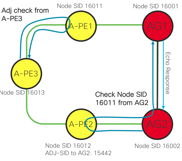
It is recommended to enable SR DPM on all CST IOS-XR nodes.
SR Data Plane Monitoring Configuration
mpls oam
  dpm
   pps 10
   interval 60 (minutes)
MPLS Segment Routing Traffic Engineering (SR-TE) configuration
The following configuration is done at the global ISIS configuration level and should be performed for all IOS-XR nodes.
router isis ACCESS
 address-family ipv4 unicast
  mpls traffic-eng level-2-only
  mpls traffic-eng router-id Loopback0
MPLS Segment Routing Traffic Engineering (SR-TE) TE metric configuration
The TE metric is used when computing SR Policy paths with the “te” or “latency” constraint type. The TE metric is carried as a TLV within the TE opaque LSA distributed across the IGP area and to the PCE via BGP-LS.
The TE metric is used in the CST 5G Transport use case. If no TE metric is defined the local CSPF or PCE will utilize the IGP metric.
segment-routing
 traffic-eng
  interface TenGigE0/0/0/6
   metric 1000
IOS-XR SR Flexible Algorithm Configuration
Segment Routing Flexible Algorithm offers a way to to easily define multiple logical network topologies satisfying a specific network constraint. Flex-Algo definitions must first be configured in each IGP domain on all nodes participating in Flex-Algo. By default, all nodes participate in Algorithm 0, mapping to “use lowest IGP metric” path computation. In the CST design, ABR nodes must have Flex-Algo definitions in both IS-IS instances if an inter-domain path is required.
Flex-Algo IS-IS Definition
Each Flex-Algo is defined on the nodes participating in the Flex-Algo. In this configuration IS-IS is configured to advertise the definition network wide. This is not required on each node in the domain, only a single node needs to advertise the definition, but there is no downside to having each node advertise the definition. In this case we are also defining a link affinity to be used in the 131 Flex-Algo. The same affinity-map must be used on all nodes in the IGP domain. The link affinity is configured under specific interfaces in the IS-IS interface configuration as shown with interface TenGigE0/0/0/20 below. The configuration for 131 is set to exclude links matching the “red” affinity, so any path utilizing Flex-Algo 131 as a constraint will not utilize the TenGigE0/0/0/20 path. The Flex-Algo link affinity is applied to both local and remote interfaces matching the affinity.
Also note non-Flex-Algo configuration can utilize link affinities, which are defined under segment-routing->traffic-engineering->interface->affinity.
As of CST 4.0, delay is the only metric-type supported. Utilizing the delay metric-type for a Flex-Algo will ensure a path will utilize only the lowest delay path, even if a single destination SID is referenced in the SR-TE path.
router isis ACCESS
  affinity-map red bit-position 0
  flex-algo 128
    advertise-definition
  !
  flex-algo 129
    advertise-definition
  !
  flex-algo 130
    metric-type delay
    advertise-definition
  !
  flex-algo 131
    advertise-definition
    affinity exclude-any red
    !
  !
  interface TenGigE0/0/0/20
    affinity flex-algo red
Flex-Algo Node SID Configuration
Flex-Algo works by allocating a globally unique node SID referencing the algorithm on each node participating in the Flex-Algo topology. This requires additional Node SID configuration on the Loopback0 interface for each router. The following is an example for a node participating in four different Flex-Algo domains in addition to the default Algo 0 domain, covered by the base Node SID configuration. Each SID belongs to the same global SRGB.
router isis ACCESS
 interface Loopback0
  address-family ipv4 unicast
   prefix-sid index 150
   prefix-sid algorithm 128 absolute 18003
   prefix-sid algorithm 129 absolute 19003
   prefix-sid algorithm 130 absolute 20003
   prefix-sid algorithm 131 absolute 21003
If one inspects the IS-IS database for the nodes, you will see the Flex-Algo SID entries.
RP/0/RP0/CPU0:NCS540-A-PE3#show isis database NCS540-A-PE3.00-00 verbose
  Router Cap:     100.0.1.50 D:0 S:0
    Segment Routing: I:1 V:0, SRGB Base: 16000 Range: 8000
    SR Local Block: Base: 15000 Range: 1000
    Node Maximum SID Depth:
      Label Imposition: 12
    SR Algorithm:
      Algorithm: 0
      Algorithm: 1
      Algorithm: 128
      Algorithm: 129
      Algorithm: 130
      Algorithm: 131
    Flex-Algo Definition:
      Algorithm: 128 Metric-Type: 0 Alg-type: 0 Priority: 128
    Flex-Algo Definition:
      Algorithm: 129 Metric-Type: 0 Alg-type: 0 Priority: 128
    Flex-Algo Definition:
      Algorithm: 130 Metric-Type: 1 Alg-type: 0 Priority: 128
    Flex-Algo Definition:
      Algorithm: 131 Metric-Type: 0 Alg-type: 0 Priority: 128
      Flex-Algo Exclude-Any Ext Admin Group:
        0x00000001
IOS-XE Nodes - SR-MPLS Transport
Segment Routing MPLS configuration
mpls label range 6001 32767 static 16 6000

segment-routing mpls
 !
 set-attributes
  address-family ipv4
   sr-label-preferred
  exit-address-family
 !
 global-block 16000 24999
 !
Prefix-SID assignment to loopback 0 configuration
 connected-prefix-sid-map
  address-family ipv4
   100.0.1.51/32 index 151 range 1
  exit-address-family
 !
Basic IGP protocol (ISIS) with Segment Routing MPLS configuration
key chain ISIS-KEY
 key 1
  key-string cisco
   accept-lifetime 00:00:00 Jan 1 2018 infinite
   send-lifetime 00:00:00 Jan 1 2018 infinite
!
router isis ACCESS
 net 49.0001.0102.0000.0254.00
 is-type level-2-only
 authentication mode md5
 authentication key-chain ISIS-KEY
 metric-style wide
 fast-flood 10
 set-overload-bit on-startup 120
 max-lsp-lifetime 65535
 lsp-refresh-interval 65000
 spf-interval 5 50 200
 prc-interval 5 50 200
 lsp-gen-interval 5 5 200
 log-adjacency-changes
 segment-routing mpls
 segment-routing prefix-sid-map advertise-local
TI-LFA FRR configuration
 fast-reroute per-prefix level-2 all
 fast-reroute ti-lfa level-2
 microloop avoidance protected
!

interface Loopback0
 ip address 100.0.1.51 255.255.255.255
 ip router isis ACCESS
 isis circuit-type level-2-only
end
IS-IS and MPLS interface configuration
interface TenGigabitEthernet0/0/12
 mtu 9216
 ip address 10.117.151.1 255.255.255.254
 ip router isis ACCESS
 mpls ip
 isis circuit-type level-2-only
 isis network point-to-point
 isis metric 100
end
MPLS Segment Routing Traffic Engineering (SR-TE)
router isis ACCESS
 mpls traffic-eng router-id Loopback0
 mpls traffic-eng level-2
Area Border Routers (ABRs) IPv4/IPv6 route distribution using BGP
The ABR nodes must provide IP reachability for RRs, SR-PCEs and NSO between ISIS-ACCESS and ISIS-CORE IGP domains. One use case is SR Tree-SID, which requires all nodes have a PCEP session to a single SR-PCE.
The recommended method to achieve reachability to nodes in the Core domain from access domain routers is to utilize BGP to advertise the Loopback addresses of specific nodes to the ABR nodes, and use either BGP to IGP redistribution or IPv4/IPv6 Unicast BGP between ABR and access nodes to distribute those routes. If unicast BGP is used, the ABR nodes will act as inline Route Reflectors.
Reachability to the access routers from the core routes is provided by advertising access domain aggregate routes from each access domain via BGP to core nodes requiring them. If the core element such as SR-PCE is a router, SR-MPLS and BGP can enabled, with the ABRs advertising the aggregates directly. If the element is not a router, then the router it is connected to will receive and advertise BGP prefixes to establish end to end connectivity.
The following is an example from one ABR node and one SR-PCE node.
Core SR-PCE BGP Configuration
The following configuration is for SR-PCE with Loopback 101.0.0.100. 101.0.0.3 and 101.0.0.4 are ABRs for one access domain, 101.0.1.1 and 101.0.1.2 the other. The optional route policies are used as a strict check to make sure only the proper routes are being received.
route-policy access1-in
  if destination in (101.0.1.0/24) then
    pass
  else
    drop
  endif
end-policy
!
route-policy access2-in
  if destination in (101.0.2.0/24) then
    pass
  else
    drop
  endif
end-policy

router bgp 100
 nsr
 bgp router-id 101.0.0.100
 bgp redistribute-internal
 bgp graceful-restart
 nexthop validation color-extcomm sr-policy
 nexthop validation color-extcomm disable
 ibgp policy out enforce-modifications
 address-family ipv4 unicast
  network 101.0.0.100/32
 !
 neighbor 101.0.0.3
  remote-as 100
  update-source Loopback0
  address-family ipv4 unicast
   route-policy access1-in in
  !
 !
 neighbor 101.0.0.4
  remote-as 100
  update-source Loopback0
  address-family ipv4 unicast
   route-policy access1-in in
  !
 !
 neighbor 101.0.1.1
  remote-as 100
  update-source Loopback0
  address-family ipv4 unicast
   route-policy access2-in in
  !
 !
 neighbor 101.0.1.2
  remote-as 100
  update-source Loopback0
  address-family ipv4 unicast
   route-policy access2-in in
  !
 !
ABR BGP Configuration
In this example the ABR node advertises the aggregate 100.0.1.0/24 covering A-PE loopback addresses in the Access-1 IGP domain to the core SR-PCE node. It uses the IPv4 unicast AFI to advertise the SR-PCE Loopback prefix to the A-PE nodes. Route policies are used to restrict the prefixes advertised in both directions.
router static
address-family ipv4 unicast
  100.0.1.0/24 Null0
prefix-set ACCESS-PE-PREFIX
  100.0.1.0/24
end-set
prefix-set SRPCE-PREFIX
  100.0.0.100/32
end-set

route-policy ABR-to-SRPCE
  if destination in ACCESS-PE-PREFIX then
    pass
  else
    drop
  endif
end-policy
!
route-policy ABR-to-APE
  if destination in SRPCE-PREFIX then
    pass
  else
    drop
  endif
end-policy
!

router bgp 100
 nsr
 bgp router-id 101.0.0.3
 bgp redistribute-internal
 bgp graceful-restart
 nexthop validation color-extcomm sr-policy
 nexthop validation color-extcomm disable
 ibgp policy out enforce-modifications
 address-family ipv4 unicast
 network 100.0.1.0/24
 !
 address-family ipv6 unicast
 !
 neighbor-group BGP-APE
  remote-as 100
  update-source Loopback0
  !
  address-family ipv4 unicast
   route-reflector-client
   route-policy ABR-to-APE out
   next-hop-self
  !
  address-family ipv6 unicast
   route-reflector-client
   next-hop-self
  !
 !
 neighbor 101.0.2.52
  use neighbor-group BGP-APE
 !
 neighbor 101.0.2.53
  use neighbor-group BGP-APE
 !
 neighbor 101.0.0.100
  description SR-PCE
  remote-as 100
  update-source Loopback0
  address-family ipv4 unicast
   route-policy ABR-to-SRPCE out
   next-hop-self
  !
 !
Deprecated Area Border Routers (ABRs) IGP-ISIS Redistribution configuration (IOS-XR)
Note the following is for historical reference and has been deprecated, IGP redistribution is not recommended for production deployments
The ABR nodes must provide IP reachability for RRs, SR-PCEs and NSO between ISIS-ACCESS and ISIS-CORE IGP domains. This is done by IP prefix redistribution. The ABR nodes have static hold-down routes for the block of IP space used in each domain across the network, those static routes are then redistributed into the domains using the redistribute static command with a route-policy. The distance command is used to ensure redistributed routes are not preferred over local IS-IS routes on the opposite ABR. The distance command must be applied to both ABR nodes.
router static
address-family ipv4 unicast
  100.0.0.0/24 Null0
  100.0.1.0/24 Null0
  100.1.0.0/24 Null0
  100.1.1.0/24 Null0
prefix-set ACCESS-PCE_SvRR-LOOPBACKS
  100.0.1.0/24,
  100.1.1.0/24
end-set
prefix-set RR-LOOPBACKS
    100.0.0.0/24,
  100.1.0.0/24
end-set
Redistribute Core SvRR and TvRR loopback into Access domain
route-policy CORE-TO-ACCESS1
  if destination in RR-LOOPBACKS then
    pass
  else
    drop
  endif
end-policy
!
router isis ACCESS
 address-family ipv4 unicast
  distance 254 0.0.0.0/0 RR-LOOPBACKS
  redistribute static route-policy CORE-TO-ACCESS1
Redistribute Access SR-PCE and SvRR loopbacks into CORE domain
route-policy ACCESS1-TO-CORE
  if destination in ACCESS-PCE_SvRR-LOOPBACKS then
    pass
  else
    drop
  endif
end-policy
!
router isis CORE
 address-family ipv4 unicast
  distance 254 0.0.0.0/0 ACCESS-PCE_SvRR-LOOPBACKS
  redistribute static route-policy CORE-TO-ACCESS1
Multicast transport using mLDP
Overview
This portion of the implementation guide instructs the user how to configure mLDP end to end across the multi-domain network. Multicast service examples are given in the “Services” section of the implementation guide.
mLDP core configuration
In order to use mLDP across the Converged SDN Transport network LDP must first be enabled. There are two mechanisms to enable LDP on physical interfaces across the network, LDP auto-configuration or manually under the MPLS LDP configuration context. The capabilities statement will ensure LDP unicast FECs are not advertised, only mLDP FECs. Recursive forwarding is required in a multi-domain network. mLDP must be enabled on all participating A-PE, PE, AG, PA, and P routers.
LDP base configuration with defined interfaces
mpls ldp
 capabilities sac mldp-only
 mldp
  logging notifications
  address-family ipv4
   make-before-break delay 30
   forwarding recursive
   recursive-fec
  !
 !
 router-id 100.0.2.53
 session protection
 address-family ipv4
 !
 interface TenGigE0/0/0/6
 !
 interface TenGigE0/0/0/7
LDP auto-configuration
LDP can automatically be enabled on all IS-IS interfaces with the following configuration in the IS-IS configuration. It is recommended to do this only after configuring all MPLS LDP properties.
router isis ACCESS
  address-family ipv4 unicast
    segment-routing mpls sr-prefer
    mpls ldp auto-config
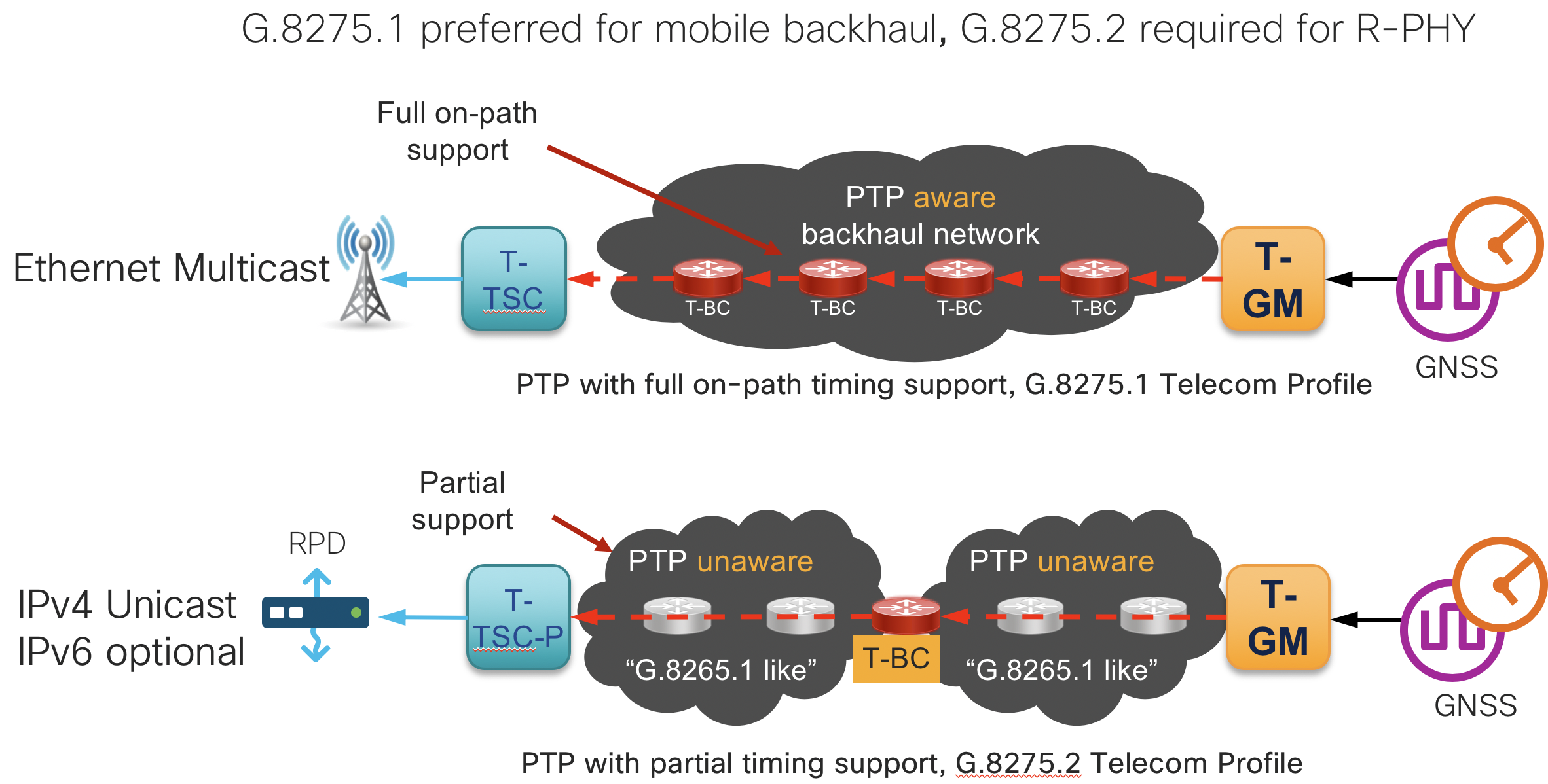
G.8275.1 and G.8275.2 PTP (1588v2) timing configuration
Summary
This section contains the base configurations used for both G.8275.1 and G.8275.2 timing. Please see the CST HLD for an overview on timing in general. G.8275.1 is the preferred method for end to end timing if possible since it provides the most accurate clock and has no limitations on interface type used for PTP peers. G.8275.1 to G.8275.2 interworking can be used on edge nodes to provide timing to devices requiring G.8275.2.
Enable frequency synchronization
In order to lock the internal oscillator to a PTP source, frequency synchronization must first be enabled globally.
frequency synchronization
 quality itu-t option 1
 clock-interface timing-mode system
 log selection changes
!
Optional Synchronous Ethernet configuration (PTP hybrid mode)
If the end-to-end devices support SyncE it should be enabled. SyncE will allow much faster frequency sync and maintain integrity for long periods of time during holdover events. Using SyncE for frequency and PTP for phase is known as “Hybrid” mode. A lower priority is used on the SyncE input (50 for SyncE vs. 100 for PTP).
interface TenGigE0/0/0/10
 frequency synchronization
  selection input
  priority 50
 !
!
PTP G.8275.2 global timing configuration
As of CST 3.0, IOS-XR supports a single PTP timing profile and single clock type in the global PTP configuration. The clock domain should follow the ITU-T guidelines for specific profiles using a domain >44 for G.8275.2 clocks.
ptp
 clock
  domain 60
  profile g.8275.2 clock-type T-BC
  !
 frequency priority 100
 time-of-day priority 50
 log
  servo events
  best-master-clock changes
 !
PTP G.8275.2 interface profile definitions
It is recommended to use “profiles” defined globally which are then applied to interfaces participating in timing. This helps minimize per-interface timing configuration. It is also recommended to define different profiles for “master” and “slave” interfaces.
IPv4 G.8275.2 master profile
The master profile is assigned to interfaces for which the router is acting as a boundary clock
ptp
 profile g82752_master_v4
  transport ipv4
  port state master-only
  sync frequency 16
  clock operation one-step <-- Note the NCS series should be configured with one-step, ASR9000 with two-step
  announce timeout 5
  announce interval 1
  unicast-grant invalid-request deny
  delay-request frequency 16
 !
!
IPv6 G.8275.2 master profile
The master profile is assigned to interfaces for which the router is acting as a boundary clock
ptp
 profile g82752_master_v6
  transport ipv6
  port state master-only
  sync frequency 16
  clock operation one-step
  announce timeout 10
  announce interval 1
  unicast-grant invalid-request deny
  delay-request frequency 16
 !
!
IPv4 G.8275.2 slave profile
The slave profile is assigned to interfaces for which the router is acting as a slave to another master clock
ptp
 profile g82752_master_v4
  transport ipv4
  port state slave-only
  sync frequency 16
  clock operation one-step <-- Note the NCS series should be configured with one-step, ASR9000 with two-step
  announce timeout 10
  announce interval 1
  unicast-grant invalid-request deny
  delay-request frequency 16
 !
!
IPv6 G.8275.2 slave profile
The slave profile is assigned to interfaces for which the router is acting as a slave to another master clock
ptp
 profile g82752_master_v6
  transport ipv6
  port state slave-only
  sync frequency 16
  clock operation one-step <-- Note the NCS series should be configured with one-step, ASR9000 with two-step
  announce timeout 10
  announce interval 1
  unicast-grant invalid-request deny
  delay-request frequency 16
 !
!
PTP G.8275.1 global timing configuration
As of CST 3.0, IOS-XR supports a single PTP timing profile and single clock type in the global PTP configuration. The clock domain should follow the ITU-T guidelines for specific profiles using a domain <44 for G.8275.1 clocks.
ptp
clock domain 24
  operation one-step Use one-step for NCS series, two-step for ASR 9000
  physical-layer-frequency
  frequency priority 100
  profile g.8275.1 clock-type T-BC
log
  servo events
  best-master-clock changes
IPv6 G.8275.1 slave profile
The slave profile is assigned to interfaces for which the router is acting as a slave to another master clock
ptp
 profile g82751_slave
  port state slave-only
  clock operation one-step <-- Note the NCS series should be configured with one-step, ASR9000 with two-step
  announce timeout 10
  announce interval 1
  delay-request frequency 16
  multicast transport ethernet
 !
!
IPv6 G.8275.1 master profile
The master profile is assigned to interfaces for which the router is acting as a master to slave devices
ptp
 profile g82751_slave
  port state master-only
  clock operation one-step <-- Note the NCS series should be configured with one-step, ASR9000 with two-step
  sync frequency 16
  announce timeout 10
  announce interval 1
  delay-request frequency 16
  multicast transport ethernet
 !
!
Application of PTP profile to physical interface
Note: In CST 3.0 PTP may only be enabled on physical interfaces. G.8275.1 operates at L2 and supports PTP across Bundle member links and interfaces part of a bridge domain. G.8275.2 operates at L3 and does not support Bundle interfaces.
G.8275.2 interface configuration
This example is of a slave device using a master of 2405:10:23:253::0.
interface TenGigE0/0/0/6
 ptp
  profile g82752_slave_v6
  master ipv6 2405:10:23:253::
  !
 !
G.8275.1 interface configuration
interface TenGigE0/0/0/6
 ptp
  profile g82751_slave
  !
 !
G.8275.1 and G.8275.2 Multi-Profile and Interworking
In CST 4.0 and IOS-XR 7.2.2 PTP Multi-Profile is supported, along with the ability to interwork between G.8275.1 and G.8275.2 on the same router. This allows a node to run one timing profile to its upstream GM peer and supply a timing reference to downstream peers using different profiles. It is recommended to use G.8275.1 as the primary profile across the network, and G.8275.2 to peers who only support the G.8275.2 profile, such as Remote PHY Devices.
The interworking feature is enabled on the client interface which has a different profile from the primary node profile. The domain must be specified along with the interop mode.
G.8275.1 Primary to G.8275.2 Configuration
interface TenGigE0/0/0/5
  ptp
   interop g.8275.2
   domain 60
   !
   transport ipv4
   port state master-only
G.8275.2 Primary to G.8275.1 Configuration
interface TenGigE0/0/0/5
  ptp
   interop g.8275.1
   domain 24
   !
   transport ethernet
   port state master-only
Segment Routing Path Computation Element (SR-PCE) configuration
router static
 address-family ipv4 unicast
  0.0.0.0/1 Null0

router bgp 100
 nsr
 bgp router-id 100.0.0.100
 bgp graceful-restart graceful-reset
 bgp graceful-restart
 ibgp policy out enforce-modifications
 address-family link-state link-state
 !
 neighbor-group TvRR
  remote-as 100
  update-source Loopback0
  address-family link-state link-state
  !
 !
 neighbor 100.0.0.10
  use neighbor-group TvRR
 !
 neighbor 100.1.0.10
  use neighbor-group TvRR
 !
!
pce
 address ipv4 100.100.100.1
 rest
  user rest_user
   password encrypted 00141215174C04140B
  !
  authentication basic
 !
 state-sync ipv4 100.100.100.2
 peer-filter ipv4 access-list pe-routers
!
BGP - Services (sRR) and Transport (tRR) route reflector configuration
Services Route Reflector (sRR) configuration
In the CST validation a sRR is used to reflect all service routes. In a production network each service could be allocated its own sRR based on resiliency and scale demands. In CST 5.0 (XR 7.5.2) and higher versions we will utilize the BGP soft next-hop validation feature to accept service prefixes without a BGP next-hop residing in the RIB.
router bgp 100
 nsr
 bgp router-id 100.0.0.200
 bgp graceful-restart
 nexthop validation color-extcomm disable
 ibgp policy out enforce-modifications
 address-family vpnv4 unicast
  nexthop trigger-delay critical 10
  additional-paths receive
  additional-paths send
 !
 address-family vpnv6 unicast
  nexthop trigger-delay critical 10
  additional-paths receive
  additional-paths send
  retain route-target all
 !
 address-family l2vpn evpn
  additional-paths receive
  additional-paths send
 !
 address-family ipv4 mvpn
  nexthop trigger-delay critical 10
  soft-reconfiguration inbound always
  !
 address-family ipv6 mvpn
  nexthop trigger-delay critical 10
  soft-reconfiguration inbound always
  !
 neighbor-group SvRR-Client
  remote-as 100
  bfd fast-detect
  bfd minimum-interval 3
  update-source Loopback0
  address-family l2vpn evpn
   route-reflector-client
   !
  address-family vpnv4 unicast
   route-reflector-client
   !
  address-family vpnv6 unicast
   route-reflector-client
   !
  address-family ipv4 mvpn
   route-reflector-client
   !
  address-family ipv6 mvpn
   route-reflector-client
  !
 !
 neighbor 100.0.0.1
  use neighbor-group SvRR-Client
 !
!
Transport Route Reflector (tRR) configuration
In CST 5.0 (XR 7.5.2) and higher versions we will utilize the BGP soft next-hop validation feature to accept BGP-LS prefixes without a BGP next-hop residing in the RIB.
router bgp 100
 nsr
 bgp router-id 100.0.0.10
 bgp graceful-restart
 nexthop validation color-extcomm disable
 ibgp policy out enforce-modifications
 address-family link-state link-state
  additional-paths receive
  additional-paths send
 !
 neighbor-group RRC
  remote-as 100
  update-source Loopback0
  address-family link-state link-state
   route-reflector-client
  !
 !
 neighbor 100.0.0.1
  use neighbor-group RRC
 !
 neighbor 100.0.0.2
  use neighbor-group RRC
!
BGP – Provider Edge Routers (A-PEx and PEx) to service RR
Each PE router is configured with BGP sessions to service route-reflectors for advertising VPN service routes across the inter-domain network.
IOS-XR configuration
In CST 5.0 (XR 7.5.2) and higher versions we will utilize the BGP soft next-hop validation feature. PE nodes will use the computed ODN SR-TE Policy as a validation criteria for the BGP path. If a SR-TE Policy can be computed either locally or by SR-PCE, the path will be active, otherwise the path will not be installed.
router bgp 100
 nsr
 bgp router-id 100.0.1.50
 bgp graceful-restart graceful-reset
 bgp graceful-restart
 nexthop validation color-extcomm sr-policy
 ibgp policy out enforce-modifications
 address-family vpnv4 unicast
 !
 address-family vpnv6 unicast
 !
 address-family ipv4 mvpn
 !
 address-family ipv6 mvpn
 !
 address-family l2vpn evpn
 !
 neighbor-group SvRR
  remote-as 100
  bfd fast-detect
  bfd minimum-interval 3
  update-source Loopback0
  address-family vpnv4 unicast
  soft-reconfiguration inbound always
  !
  address-family vpnv6 unicast
  soft-reconfiguration inbound always
  !
  address-family ipv4 mvpn
  soft-reconfiguration inbound always
  !
  address-family ipv6 mvpn
  soft-reconfiguration inbound always
  !
  address-family l2vpn evpn
  soft-reconfiguration inbound always
  !
 !
 neighbor 100.0.1.201
  use neighbor-group SvRR
  !
!
IOS-XE configuration
router bgp 100
 bgp router-id 100.0.1.51
 bgp log-neighbor-changes
 no bgp default ipv4-unicast
 neighbor SvRR peer-group
 neighbor SvRR remote-as 100
 neighbor SvRR update-source Loopback0
 neighbor 100.0.1.201 peer-group SvRR
 !
 address-family ipv4
 exit-address-family
 !
 address-family vpnv4
  neighbor SvRR send-community both
  neighbor SvRR next-hop-self
  neighbor 100.0.1.201 activate
 exit-address-family
 !
 address-family l2vpn evpn
  neighbor SvRR send-community both
  neighbor SvRR next-hop-self
  neighbor 100.0.1.201 activate
 exit-address-family
 !
BGP-LU co-existence BGP configuration
CST 3.0 introduced co-existence between services using BGP-LU and SR endpoints. If you are using SR and BGP-LU within the same domain it requires using BGP-SR in order to resolve prefixes correctly on the each ABR. BGP-SR uses a new BGP attribute attached to the BGP-LU prefix to convey the SR prefix-sid index end to end across the network. Using the same prefix-sid index both within the SR-MPLS IGP domain and across the BGP-LU network simplifies the network from an operational perspective since the path to an end node can always be identified by that SID.
It is recommended to enable the BGP-SR configuration when enabling SR on the PE node. See the PE configuration below for an example of this configuration.
Segment Routing Global Block Configuration
The BGP process must know about the SRGB in order to properly allocate local BGP-SR labels when receiving a BGP-LU prefix with a BGP-SR index community. This is done via the following configuration. If a SRGB is defined under the IGP it must match the global SRGB value. The IGP will inherit this SRGB value if none is previously defined.
segment-routing
 global-block 32000 64000
 !
!
Boundary node configuration
The following configuration is necessary on all domain boundary nodes. Note the ibgp policy out enforce-modifications command is required to change the next-hop on reflected IBGP routes.
router bgp 100
 ibgp policy out enforce-modifications
 neighbor-group BGP-LU-PE
  remote-as 100
  update-source Loopback0
  address-family ipv4 labeled-unicast
   soft-reconfiguration inbound always
   route-reflector-client
   next-hop-self
  !
 !
 neighbor-group BGP-LU-BORDER
  remote-as 100
  update-source Loopback0
  address-family ipv4 labeled-unicast
   soft-reconfiguration inbound always
   route-reflector-client
   next-hop-self
  !
 !
 neighbor 100.0.2.53
  use neighbor-group BGP-LU-PE
 !
 neighbor 100.0.2.52
  use neighbor-group BGP-LU-PE
 !
 neighbor 100.0.0.1
  use neighbor-group BGP-LU-BORDER
 !
 neighbor 100.0.0.2
  use neighbor-group BGP-LU-BORDER
 !
!
PE node configuration
The following configuration is necessary on all domain PE nodes participating in BGP-LU/BGP-SR. The label-index set must match the index of the Loopback addresses being advertised into BGP. This example shows a single Loopback address being advertised into BGP.
route-policy LOOPBACK-INTO-BGP-LU($SID-LOOPBACK0)
  set label-index $SID-LOOPBACK0
  set aigp-metric igp-cost
end-policy
!
router bgp 100
  address-family ipv4 unicast
   network 100.0.2.53/32 route-policy LOOPBACK-INTO-BGP-LU(153)
 !
 neighbor-group BGP-LU-BORDER
  remote-as 100
  update-source Loopback0
  address-family ipv4 labeled-unicast
  !
 !
 neighbor 100.0.0.3
  use neighbor-group BGP-LU-BORDER
 !
 neighbor 100.0.0.4
  use neighbor-group BGP-LU-BORDER
 !
Area Border Routers (ABRs) IGP topology distribution
Next network diagram: “BGP-LS Topology Distribution” shows how Area Border Routers (ABRs) distribute IGP network topology from ISIS ACCESS and ISIS CORE to Transport Route-Reflectors (tRRs). tRRs then reflect topology to Segment Routing Path Computation Element (SR-PCEs). Each SR-PCE has full visibility of the entire inter-domain network.
Note: Each IS-IS process in the network requires a unique instance-id to identify itself to the PCE.
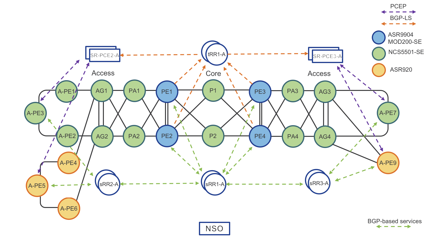
Figure 5: BGP-LS Topology Distribution
router isis ACCESS
 **distribute link-state instance-id 101**
 net 49.0001.0101.0000.0001.00
 address-family ipv4 unicast
  mpls traffic-eng router-id Loopback0
  !
!
router isis CORE
 **distribute link-state instance-id 100**
 net 49.0001.0100.0000.0001.00
 address-family ipv4 unicast
  mpls traffic-eng router-id Loopback0
  !
!
router bgp 100
 **address-family link-state link-state**
 !
 neighbor-group TvRR
  remote-as 100
  update-source Loopback0
  address-family link-state link-state
  !
  neighbor 100.0.0.10
  use neighbor-group TvRR
 !
 neighbor 100.1.0.10
  use neighbor-group TvRR
 !
Segment Routing Traffic Engineering (SR-TE) and Services Integration
This section shows how to integrate Traffic Engineering (SR-TE) with services. ODN is configured by first defining a global ODN color associated with specific SR Policy constraints. The color and BGP next-hop address on the service route will be used to dynamically instantiate a SR Policy to the remote VPN endpoint.
On Demand Next-Hop (ODN) configuration – IOS-XR
The following is an example of the elements needed in addition to the base SR configuration. An on-demand policy must be created matching the a color to set the attributes of the SR-TE Policy. ODN does not require PCEP, but for inter-domain path computation is required.
On-Demand Route Policies
Coloring service routes requires routing policies to set a specific extended community on those routes and apply the policy during the import and export of the routes. Coloring can be performed in a policy at the BGP neighbor level or at the individual service level. The following example shows global level coloring, however it is recommended for granularity and ease of management to color routes at the service level.
In CST 5.0 (XR 7.5.2) or higher ODN policies can be applied on import or export for L3VPN prefixes. EVPN Type1/3 prefixes must be applied on export.
Community Set and Routing Policy Definition
extcommunity-set opaque BLUE
  100
end-set

route-policy ODN
  set extcommunity color BLUE
end-policy

route-policy c2001
  if evpn-route-type is 1 then
    set extcommunity color c2001
  elseif evpn-route-type is 3 then
    set extcommunity color c2002
  endif
end-policy
Neighbor level application
router bgp 100
  neighbor-group SVRR-EVPN
    address-family l2vpn evpn
      route-policy ODN_EVPN out
Service level application
vrf ODN-L3VPN
 rd 100:1
 address-family ipv4 unicast
  import route-target
   100:1
  !
  export route-target
  export route-policy ODN-L3VPN-OUT
   100:1
!
evpn
 evi 2001
  bgp
   route-policy export c2001
segment-routing
 traffic-eng
  logging
   policy status
  !
  on-demand color 100
   dynamic
    pce
    !
    metric
     type igp
    !
   !
  !
  pcc
   source-address ipv4 100.0.1.50
   pce address ipv4 100.0.1.101
   !
   pce address ipv4 100.1.1.101
On Demand Next-Hop (ODN) configuration – IOS-XE
mpls traffic-eng tunnels
mpls traffic-eng pcc peer 100.0.1.101 source 100.0.1.51
mpls traffic-eng pcc peer 100.0.1.111 source 100.0.1.51
mpls traffic-eng pcc report-all
mpls traffic-eng auto-tunnel p2p config unnumbered-interface Loopback0
mpls traffic-eng auto-tunnel p2p tunnel-num min 1000 max 5000
!
mpls traffic-eng lsp attributes L3VPN-SRTE
 path-selection metric igp
 pce
!
ip community-list 1 permit 9999
!
route-map L3VPN-ODN-TE-INIT permit 10
 match community 1
 set attribute-set L3VPN-SRTE
!
route-map L3VPN-SR-ODN-Mark-Comm permit 10
 match ip address L3VPN-ODN-Prefixes
 set community 9999
 !
!
router bgp 100
 address-family vpnv4
  neighbor SvRR send-community both
  neighbor SvRR route-map L3VPN-ODN-TE-INIT in
  neighbor SvRR route-map L3VPN-SR-ODN-Mark-Comm out
SR-PCE configuration – IOS-XR
segment-routing
 traffic-eng
  pcc
   source-address ipv4 100.0.1.50
   pce address ipv4 100.0.1.101
     precedence 100
   !
   pce address ipv4 100.1.1.101
     precedence 200
   !
   report-all
   timers delegation-timeout 10
   timers deadtimer 60
   timers initiated state 15
   timers initiated orphan 10
   !
  !
SR-PCE configuration – IOS-XE
mpls traffic-eng tunnels
mpls traffic-eng pcc peer 100.0.1.101 source 100.0.1.51
mpls traffic-eng pcc peer 100.0.1.111 source 100.0.1.51
mpls traffic-eng pcc report-all
SR-TE Policy Configuration
At the foundation of CST is the use of Segment Routing Traffic Engineering Policies. SR-TE allow providers to create end to end traffic paths with engineered constraints to achieve a SLA objective. SR-TE Policies are either dynamically created by ODN (see ODN section) or users can configure SR-TE Policies on the head-end node.
SR-TE Color and Endpoint
The components uniquely identifying a SR-TE Policy to a destination PE node are its endpoint and color.
- The endpoint is the destination node loopback address. Note the endpoint address should not be an anycast address.
- The color is a 32-bit value which should have a SLA meaning to the network. The color allows for multiple SR-TE Policies to exist between a pair of nodes, each one with its own set of metrics and constraints.
SR-TE Candidate Paths
- Each SR-TE Policy configured on a node must have at least one candidate path defined.
- If multiple candidate paths are defined, only one is active at any one time.
- The candidate path with the higher preference value is preferred over candidate paths with a lower preference value.
- The candidate path configuration specifies whether the path is dynamic or uses an explicit segment list.
- Within the dynamic configuration one can specify whether to use a PCE or not, the metric type used in the path computation (IGP metric, latency, TE metric, hop count), and the additional constraints placed on the path (link affinities, flex-algo constraints, or a cumulative metric of type IGP metric, latency, TE Metric, or hop count)
- There is a default candidate path with a preference of 200 using head-end IGP path computation
- Each candidate path can have multiple explicit segment lists defined with a bandwidth weight value to load balance traffic across multiple explicit paths
Service to SR-TE Policy Forwarding - Per-Destination
Service traffic can be forwarded over SR-TE Policies in the CST design using per-destination automated steering. Per-destination steering utilizes two BGP components of the service route to forward traffic to a matching SR Policy
- A color extended community attached to the service route matching the SR Policy color
- The BGP next-hop address of the service route to match the endpoint of the SR Policy
Service to SR-TE Policy Forwarding - Per-Flow
Service traffic can also be forwarded over SR-TE Policies in the CST design using per-flow automated steering.
Per-flow automated steering uses the same BGP criteria as per-destination steering but also uses the CoS of the ingress packet to determine the proper SR Policy to steer traffic over.
SR-TE and ODN Configuration Examples
The following examples show SR-TE policies using persistent device configuration and the ODN policies to dynamic create the same SR Policies.
SR Policy using IGP metric, head-end computation
The local PE device will compute a path using the lowest cumulative IGP metric path to 100.0.1.50. Note in the multi-domain CST design, this computation will fail to nodes not found within the same IS-IS domain as the PE.
segment-routing
 traffic-eng
  policy GREEN-PE3-24
   color 1024 end-point ipv4 100.0.1.50
   candidate-paths
    preference 1
     dynamic
      !
      metric
       type igp
segment-routing
 traffic-eng
  on-demand color 1024
    dynamic
      pcep
      !
      anycast-sid-inclusion
      !
      sid-algorithm 128
    !
PCE delegated SR Policy using lowest IGP metric
This policy will request a path from the configured primary PCE with the lowest cumulative IGP metric to the endpoint 100.0.1.50
segment-routing
 traffic-eng
  policy GREEN-PE3-24
   color 1024 end-point ipv4 100.0.1.50
   candidate-paths
    preference 1
     dynamic
      pcep
      !
      metric
       type igp
PCE delegated SR Policy using lowest latency metric
This policy will request a path from the configured primary PCE with the lowest cumulative latency to the endpoint 100.0.1.50. As covered in the performance-measurement section, the per-link latency metric value used will be the dynamic/static PM value, a configured TE metric value, or the IGP metric.
segment-routing
 traffic-eng
  policy GREEN-PE3-24
   color 1024 end-point ipv4 100.0.1.50
   candidate-paths
    preference 1
     dynamic
      pcep
      !
      metric
       type latency
segment-routing
 traffic-eng
  on-demand color 1024
    dynamic
      pcep
      !
      metric
        type latency
    !
PCE delegated SR Policy including Anycast SIDs
Anycast SIDs provide redundancy to hops in the SR-TE path. 1+N nodes share the same Loopback address and Node-SID. Traffic with the Anycast SID in the SID list will route to the closest node with the SID assigned based on IGP cost. The “anycast-sid-inclusion” command is required for the PCE or local computation to prefer Anycast SIDs when computing the end to end path.
policy Anycast-APE3-1
   color 30001 end-point ipv4 101.0.1.50
   candidate-paths
    preference 1
     dynamic
      pcep
      !
      metric
       type igp
      !
    anycast-sid-inclusion
segment-routing
 traffic-eng
  on-demand color 30001
    dynamic
      pcep
      !
      anycast-sid-inclusion
    !
PCE delegated SR Policy using specific Flexible Algorithm
Please see the Flex-Algo section for more details on SR Flexible Algorithms. The following SR-TE policy will restrict path computation to links and nodes belonging to algo 128, using the lowest IGP metric to compute the path.
policy FA128-APE3-1
   color 77801 end-point ipv4 101.0.1.50
   candidate-paths
    preference 1
     dynamic
      pcep
      !
      metric
       type igp
      !
     !
     constraints
      segments
       sid-algorithm 128
on-demand color 77801
   dynamic
    pcep
    !
    metric
     type igp
    !
   !
   constraints
    segments
     sid-algorithm 128
SR Policy using explicit segment list
This policy does not perform any path computation, it will utilize the statically defined segment lists as the forwarding path across the network. The node does however check the validity of the node segments in the list. Each node SID in the segment list can be defined by either IP address or SID. The full path to the egress node must be defined in the list, but you do not need to define every node explicitly in the path. If you want the path to take a specific link the correct node and adjacency SID must be defined in the list. Multiple explicit paths can be defined with a weight assigned, the ratio of weights is used to balance traffic across each explicit path.
segment-routing
 traffic-eng
  segment-list anycast-path
   index 1 mpls label 17034
   index 2 mpls label 16150
  !
  policy anycast-path-ape3
   color 9999 end-point ipv4 100.0.1.50
   candidate-paths
    preference 1
     explicit segment-list anycast-path
Per-Flow Segment Routing Configuration (NCS Platforms)
The following configuration is required on the NCS 5500 / 5700 platforms to allocate the PFP Binding SID (BSID) from a specific label block.
mpls label blocks
  block name sample-pfp-bsid-block type pfp start 40000 end 41000 client any
Per-Flow QoS Configuration
The Forward Class must be set in the ingress QoS policy so traffic is steered into the correct child Per-Destination Policy.
policy-map per-flow-steering
 class MatchIPP1
 set forward-class 1
!
 class MatchIPP2
 set forward-class 2
!
 class MatchIPv4_SRC
 set forward-class 3
!
 class MatchIPv6_SRC
 set forward-class 4
end-policy-map
!

class-map match-any MatchIPP1
 match precedence 1
end-class-map
!
class-map match-any MatchIPP2
 match precedence 2
end-class-map
!
class-map match-any MatchIPv4_SRC
  match access-group ipv4 ipv4_sources
end-class-map
!
class-map match-any MatchIPv6_SRC
  match access-group ipv4 ipv6_sources
end-class-map

ipv4 access-list ipv4_sources
  10 permit ipv4 100.0.0.0/24 any
  20 permit ipv4 100.0.1.0/24 any
 !
ipv6 access-list ipv6_sources
 10 permit ipv6 2001:100::/64 any
 20 permit ipv6 2001:200::/64 any
Per-Flow Policy Configuration
This example shows both the child Per-Destination Policies as well as the parent Per-Flow Policy. Each Forward-Class is mapped to the color of the child policy. The default Forward Class is meant to catch traffic not matching a configured Forward Class.
segment-routing
  traffic-eng
    policy PERFLOW
     color 100 endpoint 1.1.1.4
      candidate-paths
       preference 100
        per-flow
         forward-class 0 color 10
         forward-class 1 color 20
         forward-class 2 color 30
         forward-class 3 color 40
         forward-class 4 color 50
         forward-class default 0
     !
     policy pe1_fc0
      color 10 end-point ipv4 192.168.11.1
      candidate-paths
        preference 150
        explicit segment-list PFL4-PE1-FC1
     !
     policy pe1_fc1
      color 20 end-point ipv4 192.168.11.1
      candidate-paths
        preference 150
        dynamic
     !
     policy pe1_fc2
      color 30 end-point ipv4 192.168.11.1
      candidate-paths
        preference 150
        explicit segment-list PFL4-PE1-FC2
     !
     policy pe1_fc3
      color 40 end-point ipv4 192.168.11.1
      candidate-paths
        preference 150
        dynamic
On-Demand Next-Hop Per-Flow Configuration
The creation of the SR-TE Policies can be fully automated using ODN. ODN is used to create the child Per-Destination Policies as well as the Per-Flow Policy.
segment-routing
  traffic-eng
    on-demand color 10
     dynamic
     metric
       type igp
      !
     !
    !
    on-demand color 20
     dynamic
      sid-algorithm 128
      !
    !
    on-demand color 30
     dynamic
      metric
       type te
      !
    !
    on-demand color 30
     dynamic
       metric
        type igp
      !
    !
    on-demand color 50
     dynamic
       metric
        type latency
      !
    !
    on-demand color 100
     per-flow
      forward-class 0 color 10
      forward-class 1 color 20
      forward-class 2 color 30
      forward-class 3 color 40
      forward-class 4 color 50
QoS Implementation
Summary
Please see the CST 3.0 HLD for in-depth information on design choices.
Core QoS configuration
The core QoS policies defined for CST 3.0 utilize priority levels, with no bandwidth guarantees per traffic class. In a production network it is recommended to analyze traffic flows and determine an appropriate BW guarantee per traffic class. The core QoS uses four classes. Note the “video” class uses priority level 6 since only levels 6 and 7 are supported for high priority multicast.
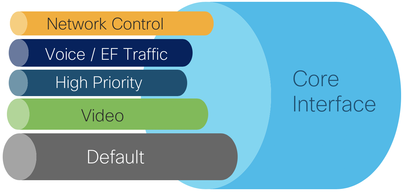
| Traffic Type | Priority Level | Core EXP Marking | |
|---|---|---|---|
| Network Control | 1 | 6 | |
| Voice | 2 | 5 | |
| High Priority | 3 | 4 | |
| Video | 6 | 2 | |
| Default | 0 | 0 |
Class maps used in QoS policies
Class maps are used within a policy map to match packet criteria or internal QoS markings like traffic-class or qos-group
class-map match-any match-ef-exp5
 description High priority, EF
 match dscp 46
 match mpls experimental topmost 5
 end-class-map
!
class-map match-any match-cs5-exp4
 description Second highest priority
 match dscp 40
 match mpls experimental topmost 4
 end-class-map
!
class-map match-any match-video-cs4-exp2
 description Video
 match dscp 32
 match mpls experimental topmost 2
 end-class-map
!
class-map match-any match-cs6-exp6
 description Highest priority control-plane traffic
 match dscp cs6
 match mpls experimental topmost 6
 end-class-map
!
class-map match-any match-qos-group-1
 match qos-group 1
 end-class-map
!
class-map match-any match-qos-group-2
 match qos-group 2
 end-class-map
!
class-map match-any match-qos-group-3
 match qos-group 3
 end-class-map
!
class-map match-any match-qos-group-6
 match qos-group 3
 end-class-map
!
class-map match-any match-traffic-class-1
 description "Match highest priority traffic-class 1"
 match traffic-class 1
 end-class-map
!
class-map match-any match-traffic-class-2
 description "Match high priority traffic-class 2"
 match traffic-class 2
 end-class-map
!
class-map match-any match-traffic-class-3
 description "Match medium traffic-class 3"
 match traffic-class 3
 end-class-map
!
class-map match-any match-traffic-class-6
 description "Match video traffic-class 6"
 match traffic-class 6
 end-class-map
Core ingress classifier policy
policy-map core-ingress-classifier
 class match-cs6-exp6
  set traffic-class 1
 !
 class match-ef-exp5
  set traffic-class 2
 !
 class match-cs5-exp4
  set traffic-class 3
 !
 class match-video-cs4-exp2
  set traffic-class 6
 !
 class class-default
  set mpls experimental topmost 0
  set traffic-class 0
  set dscp 0
 !
 end-policy-map
!
Core egress queueing map
policy-map core-egress-queuing
 class match-traffic-class-2
  priority level 2
  queue-limit 100 us
 !
 class match-traffic-class-3
  priority level 3
  queue-limit 500 us
 !
 class match-traffic-class-6
  priority level 6
  queue-limit 500 us
 !
 class match-traffic-class-1
  priority level 1
  queue-limit 500 us
 !
 class class-default
  queue-limit 250 ms
 !
 end-policy-map
!
Core egress MPLS EXP marking map
The following policy must be applied for PE devices with MPLS-based VPN services in order for service traffic classified in a specific QoS Group to be marked. VLAN-based P2P L2VPN services will by default inspect the incoming 802.1p bits and copy those the egress MPLS EXP if no specific ingress policy overrides that behavior. Note the EXP can be set in either an ingress or egress QoS policy. This QoS example sets the EXP via the egress map.
policy-map core-egress-exp-marking
 class match-qos-group-1
  set mpls experimental imposition 6
 !
 class match-qos-group-2
  set mpls experimental imposition 5
 !
 class match-qos-group-3
  set mpls experimental imposition 4
 !
 class match-qos-group-6
  set mpls experimental imposition 2
 !
 class class-default
  set mpls experimental imposition 0
 !
 end-policy-map
!
H-QoS configuration
Enabling H-QoS on NCS 540 and NCS 5500
Enabling H-QoS on the NCS platforms requires the following global command and requires a reload of the device.
hw-module profile qos hqos-enable
Example H-QoS policy for 5G services
The following H-QoS policy represents an example QoS policy reserving 5Gbps on a sub-interface. On ingress each child class is policed to a certain percentage of the 5Gbps policer. In the egress queuing policy, shaping is used with guaranteed each class a certain amount of egress bandwidth, with high priority traffic being serviced in a low-latency queue (LLQ).
Class maps used in ingress H-QoS policies
class-map match-any edge-hqos-2-in
 match dscp 46
 end-class-map
!
class-map match-any edge-hqos-3-in
 match dscp 40
 end-class-map
!
class-map match-any edge-hqos-6-in
 match dscp 32
 end-class-map
Parent ingress QoS policy
policy-map hqos-ingress-parent-5g
 class class-default
  service-policy hqos-ingress-child-policer
  police rate 5 gbps
  !
 !
 end-policy-map
H-QoS ingress child policies
policy-map hqos-ingress-child-policer
 class edge-hqos-2-in
  set traffic-class 2
  police rate percent 10
  !
 !
 class edge-hqos-3-in
  set traffic-class 3
  police rate percent 30
  !
 !
 class edge-hqos-6-in
  set traffic-class 6
  police rate percent 30
  !
 !
 class class-default
  set traffic-class 0
  set dscp 0
  police rate percent 100
  !
 !
 end-policy-map
Egress H-QoS parent policy (Priority levels)
policy-map hqos-egress-parent-4g-priority
 class class-default
  service-policy hqos-egress-child-priority
  shape average 4 gbps
 !
 end-policy-map
!
Egress H-QoS child using priority only
In this policy all classes can access 100% of the bandwidth, queues are services based on priority level. The lower priority level has preference.
policy-map hqos-egress-child-priority
 class match-traffic-class-2
  shape average percent 100
  priority level 2
 !
 class match-traffic-class-3
  shape average percent 100
  priority level 3
 !
 class match-traffic-class-6
  priority level 4
  shape average percent 100
 !
 class class-default
 !
 end-policy-map
Egress H-QoS child using reserved bandwidth
In this policy each class is reserved a certain percentage of bandwidth. Each class may utilize up to 100% of the bandwidth, if traffic exceeds the guaranteed bandwidth it is eligible for drop.
policy-map hqos-egress-child-bw
 class match-traffic-class-2
  bandwidth remaining percent 30
 !
 class match-traffic-class-3
  bandwidth remaining percent 30
 !
 class match-traffic-class-6
  bandwidth remaining percent 30
 !
 class class-default
  bandwidth remaining percent 10
 !
 end-policy-map
Egress H-QoS child using shaping
In this policy each class is shaped to a defined amount and cannot exceed the defined bandwidth.
policy-map hqos-egress-child-shaping
 class match-traffic-class-2
  shape average percent 30
 !
 class match-traffic-class-3
  shape average percent 30
 !
 class match-traffic-class-6
  shape average percent 30
 !
 class class-default
  shape average percent 10
 !
 end-policy-map
!
Support for Time Sensitive Networking in N540-FH-CSR-SYS and N540-FH-AGG-SYS
The Fronthaul family of NCS 540 routers support frame preemption based on the IEEE 802.1Qbu-2016 and Time Sensitive Networking (TSN) standards.
Time Sensitive Networking (TSN) is a set of IEEE standards that addresses the timing-critical aspect of signal flow in a packet switched Ethernet network to ensure deterministic operation. TSN operates at the Ethernet layer on physical interfaces. Frames are marked with a specific QoS class (typically 7 in a device with classes 0-7) qualify as express traffic, while other classes other than control plane traffic are marked as preemptable traffic.
This allows critical signaling traffic to traverse a device as quickly as possible without having to wait for lower priority frames before being transmitted on the wire.
Please see the TSN configuration guide for NCS 540 Fronthaul routers at https://www.cisco.com/c/en/us/td/docs/iosxr/ncs5xx/fronthaul/b-fronthaul-config-guide-ncs540-fh/m-fh-tsn-ncs540.pdf
Time Sensitive Networking Configuration
class-map match-any express-traffic
  match cos 7
class-map match-any preemptable-traffic
  match cos 2
class-map match-any express-class
  match traffic-class 7
class-map match-any preemptable-class
  match traffic-class 2
policy-map mark-traffic
  class express-traffic
    set traffic-class 7
  class preemptable-traffic
    set traffic-class 2
policy-map tsn-policy
  class express-class
    priority level 1
  class preemptable-class
    priority level 2
  class best-effort
    bandwidth percent 50
Ingress Interface
interface TenGigabitEthernet0/0/0/1
  ip address 14.0.0.1 255.255.255.0
  service-policy input mark-traffic
Egress Interface
interface TenGigabitEthernet0/0/0/0
  ip address 12.0.0.1 255.255.255.0
  service-policy output tsn-policy
  frame-preemption
Services
End-To-End VPN Services
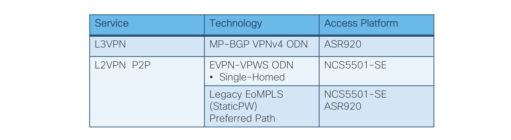
Figure 6: End-To-End Services Table
End-To-End VPN Services Data Plane
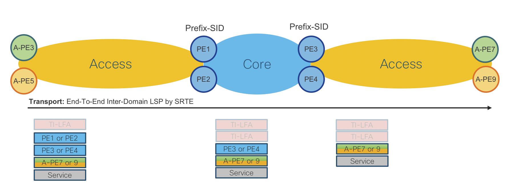
Figure 10: End-To-End Services Data Plane
L3VPN MP-BGP VPNv4 On-Demand Next-Hop
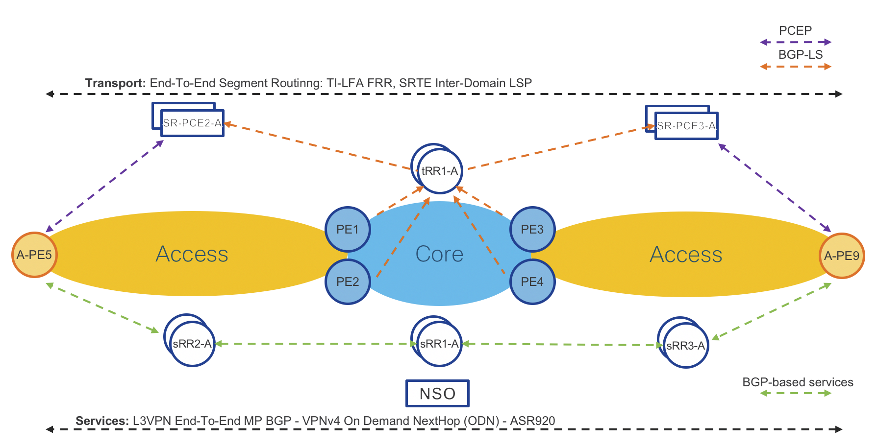
Figure 7: L3VPN MP-BGP VPNv4 On-Demand Next-Hop Control Plane
Access Routers: Cisco ASR920 IOS-XE and NCS540 IOS-XR
Operator: New VPNv4 instance via CLI or NSO
Access Router: Advertises/receives VPNv4 routes to/from Services Route-Reflector (sRR)
Access Router: Request SR-PCE to provide path (shortest IGP metric) to remote access router
SR-PCE: Computes and provides the path to remote router(s)
Access Router: Programs Segment Routing Traffic Engineering (SRTE) Policy to reach remote access router
Please refer to “On Demand Next-Hop (ODN)” sections for initial ODN configuration.
Access Router Service Provisioning (IOS-XR)
ODN route-policy configuration
extcommunity-set opaque ODN-GREEN
  100
end-set

route-policy ODN-L3VPN-OUT
  set extcommunity color ODN-GREEN
  pass
end-policy
VRF definition configuration
vrf ODN-L3VPN
 rd 100:1
 address-family ipv4 unicast
  import route-target
   100:1
  !
  export route-target
  export route-policy ODN-L3VPN-OUT
   100:1
  !
 !
 address-family ipv6 unicast
  import route-target
   100:1
  !
  export route-target
  export route-policy ODN-L3VPN-OUT
   100:1
  !
 !
VRF Interface configuration
interface TenGigE0/0/0/23.2000
 mtu 9216
 vrf ODN-L3VPN
 ipv4 address 172.106.1.1 255.255.255.0
 encapsulation dot1q 2000
BGP VRF configuration with static/connected only
router bgp 100
 vrf VRF-MLDP
  rd auto
  address-family ipv4 unicast
   redistribute connected
   redistribute static
  !
  address-family ipv6 unicast
   redistribute connected
   redistribute static
  !
Access Router Service Provisioning (IOS-XE)
VRF definition configuration
vrf definition L3VPN-SRODN-1
 rd 100:100
 route-target export 100:100
 route-target import 100:100
 address-family ipv4
 exit-address-family
VRF Interface configuration
interface GigabitEthernet0/0/2
 mtu 9216
 vrf forwarding L3VPN-SRODN-1
 ip address 10.5.1.1 255.255.255.0
 negotiation auto
end
BGP VRF configuration Static & BGP neighbor
Static routing configuration
router bgp 100
 address-family ipv4 vrf L3VPN-SRODN-1
  redistribute connected
 exit-address-family
BGP neighbor configuration
router bgp 100
 neighbor Customer-1 peer-group
 neighbor Customer-1 remote-as 200
 neighbor 10.10.10.1 peer-group Customer-1
 address-family ipv4 vrf L3VPN-SRODN-2
   neighbor 10.10.10.1 activate
 exit-address-family
L2VPN Single-Homed EVPN-VPWS On-Demand Next-Hop
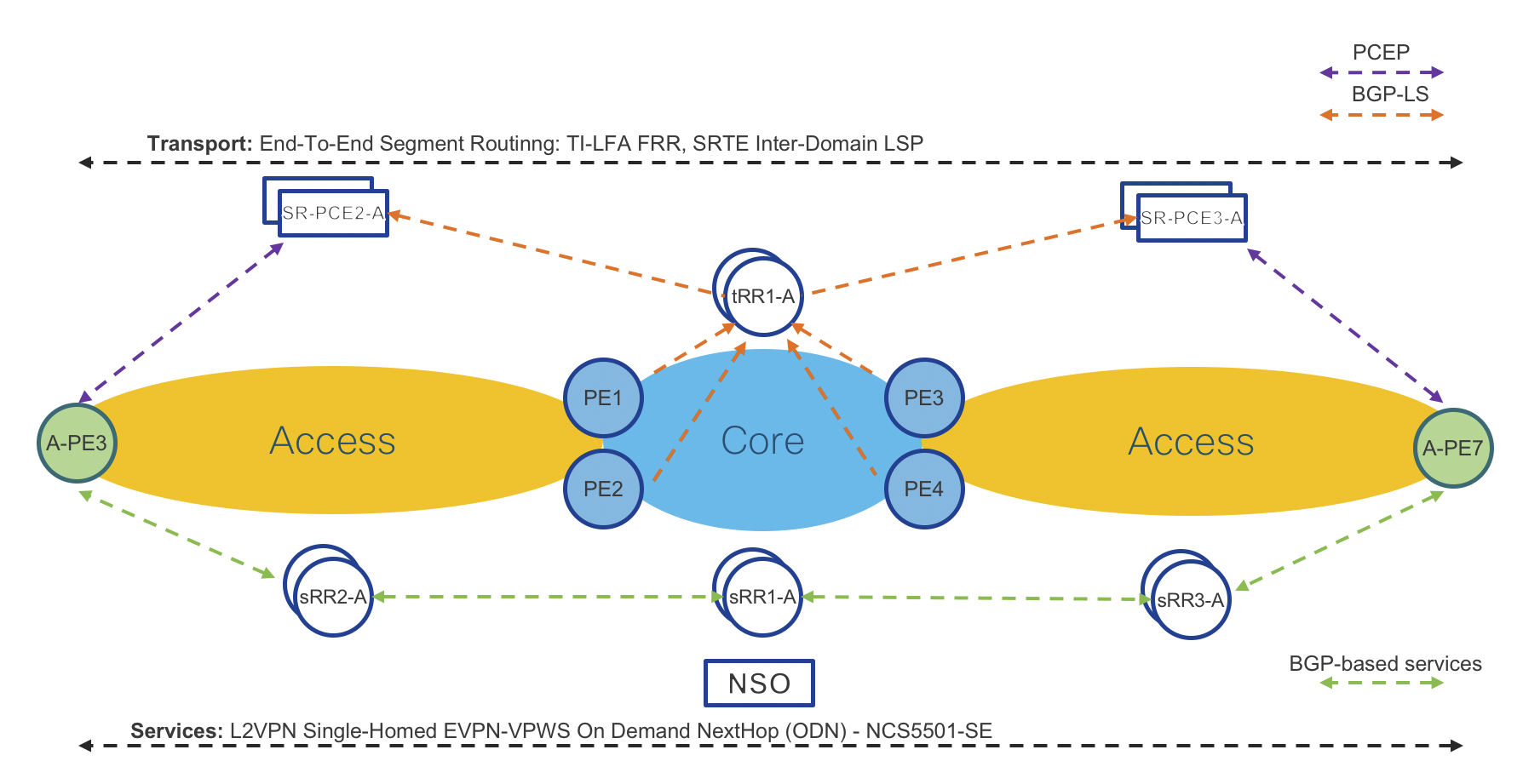
Figure 8: L2VPN Single-Homed EVPN-VPWS On-Demand Next-Hop Control Plane
Access Routers: Cisco NCS5501-SE IOS-XR
Operator: New EVPN-VPWS instance via CLI or NSO
Access Router: Advertises/receives EVPN-VPWS instance to/from Services Route-Reflector (sRR)
Access Router: Request SR-PCE to provide path (shortest IGP metric) to remote access router
SR-PCE: Computes and provides the path to remote router(s)
Access Router: Programs Segment Routing Traffic Engineering (SRTE) Policy to reach remote access router
Note: Please refer to On Demand Next-Hop (ODN) – IOS-XR section for initial ODN configuration. The correct EVPN L2VPN routes must be advertised with a specific color ext-community to trigger dynamic SR Policy instantiation.
Access Router Service Provisioning (IOS-XR):
Port based service configuration
l2vpn                                                                                                                           xconnect group evpn_vpws
 p2p odn-1
  interface TenGigE0/0/0/5
   neighbor evpn evi 1000 target 1 source 1

interface TenGigE0/0/0/5
  l2transport
VLAN Based service configuration
l2vpn
 xconnect group evpn_vpws
 p2p odn-1
  neighbor evpn evi 1000 target 1 source 1
  !
!
interface TenGigE0/0/0/5.1 l2transport
 encapsulation dot1q 1
 rewrite ingress tag pop 1 symmetric
!
L2VPN Static Pseudowire (PW) – Preferred Path (PCEP)
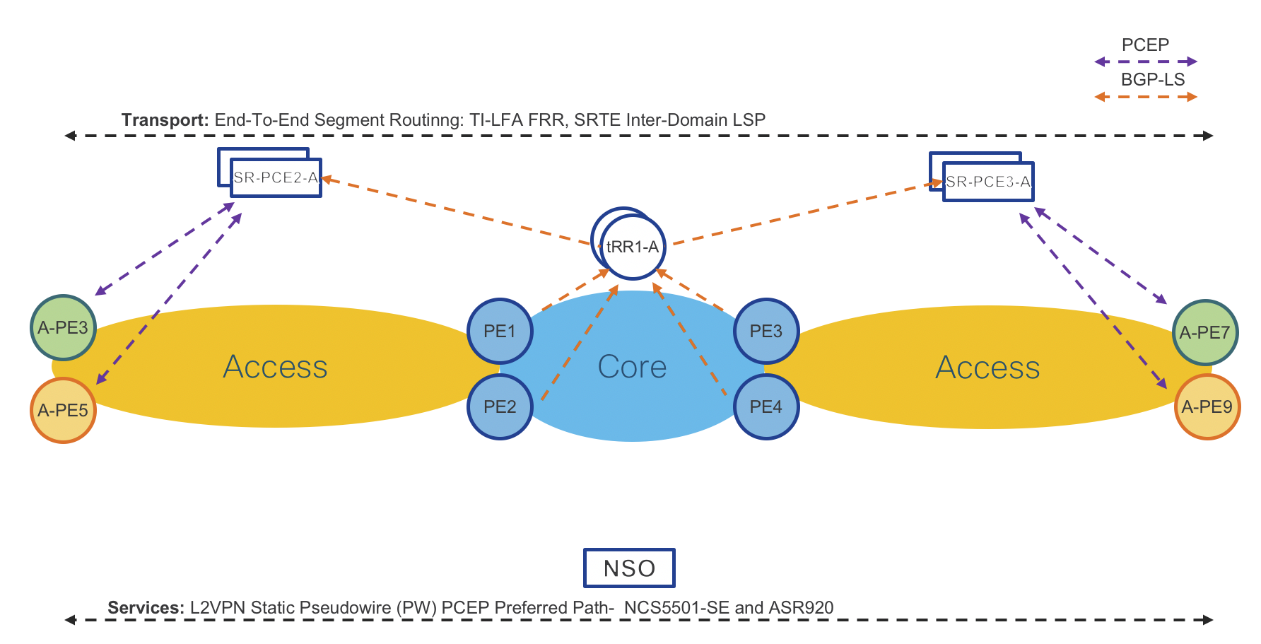
Figure 9: L2VPN Static Pseudowire (PW) – Preferred Path (PCEP) Control Plane
Access Routers: Cisco NCS5501-SE IOS-XR or Cisco ASR920 IOS-XE
Operator: New Static Pseudowire (PW) instance via CLI or NSO
Access Router: Request SR-PCE to provide path (shortest IGP metric) to remote access router
SR-PCE: Computes and provides the path to remote router(s)
Access Router: Programs Segment Routing Traffic Engineering (SRTE) Policy to reach remote access router
Access Router Service Provisioning (IOS-XR):
Note: EVPN VPWS dual homing is not supported when using an SR-TE preferred path.
Note: In IOS-XR 6.6.3 the SR Policy used as the preferred path must be referenced by its generated name and not the configured policy name. This requires first issuing the command
Define SR Policy
 traffic-eng
  policy GREEN-PE3-1
   color 1001 end-point ipv4 100.0.1.50
   candidate-paths
    preference 1
     dynamic
      pcep
      !
      metric
       type igp
Determine auto-configured policy name The auto-configured policy name will be persistant and must be used as a reference in the L2VPN preferred-path configuration.
RP/0/RP0/CPU0:A-PE8#show segment-routing traffic-eng policy candidate-path name GREEN-PE3-1

SR-TE policy database
Color: 1001, End-point: 100.0.1.50
  Name: srte_c_1001_ep_100.0.1.50
Port Based Service configuration
interface TenGigE0/0/0/15
  l2transport
  !
!
l2vpn
 pw-class static-pw-class-PE3
  encapsulation mpls
   control-word
   preferred-path sr-te policy srte_c_1001_ep_100.0.1.50
   !
  !
 !
 p2p Static-PW-to-PE3-1
  interface TenGigE0/0/0/15
   neighbor ipv4 100.0.0.3 pw-id 1000
    mpls static label local 1000 remote 1000 pw-class static-pw-class-PE3
VLAN Based Service configuration
interface TenGigE0/0/0/5.1001 l2transport
 encapsulation dot1q 1001
 rewrite ingress tag pop 1 symmetric
 !
!
l2vpn
 pw-class static-pw-class-PE3
  encapsulation mpls
   control-word
   preferred-path sr-te policy srte_c_1001_ep_100.0.1.50
  p2p Static-PW-to-PE7-2
   interface TenGigE0/0/0/5.1001
    neighbor ipv4 100.0.0.3 pw-id 1001
     mpls static label local 1001 remote 1001 pw-class static-pw-class-PE3
Access Router Service Provisioning (IOS-XE):
Port Based service with Static OAM configuration
interface GigabitEthernet0/0/1
 mtu 9216
 no ip address
 negotiation auto
 no keepalive
 service instance 10 ethernet
  encapsulation default
  xconnect 100.0.2.54 100 encapsulation mpls manual pw-class mpls
   mpls label 100 100
   no mpls control-word
 !
 pseudowire-static-oam class static-oam
  timeout refresh send 10
  ttl 255
  !
 !
!
pseudowire-class mpls
 encapsulation mpls
 no control-word
 protocol none
 preferred-path interface Tunnel1
 status protocol notification static static-oam
!
VLAN Based Service configuration
interface GigabitEthernet0/0/1
 no ip address
 negotiation auto
 service instance 1 ethernet Static-VPWS-EVC
  encapsulation dot1q 10
  rewrite ingress tag pop 1 symmetric
  xconnect 100.0.2.54 100 encapsulation mpls manual pw-class mpls
   mpls label 100 100
   no mpls control-word
   !
  !
!
pseudowire-class mpls
 encapsulation mpls
 no control-word
 protocol none
 preferred-path interface Tunnel1
L2VPN EVPN E-Tree
Note: ODN support for EVPN E-Tree is supported on ASR9K only in CST 3.5. Support for E-Tree across all CST IOS-XR nodes will be covered in CST 4.0 based on IOS-XR 7.2.2. In CST 3.5, if using E-Tree across multiple IGP domains, SR-TE Policies must be configured between all Root nodes and between all Root and Leaf nodes.
IOS-XR Root Node Configuraiton
evpn
  evi 100
   advertise-mac
  !
 !
l2vpn
 bridge group etree
  bridge-domain etree-ftth
  interface TenGigE0/0/0/14.100
  routed interface BVI100
  !
  evi 100
IOS-XR Leaf Node Configuration
A single command is needed to enable leaf function for an EVI. Configuring “etree leaf” will signal to other nodes this is a leaf node. In this case we also have a L3 IRB configured within the EVI. In order to isolate the two ACs, each AC is configured with the “split-horizon group” configuration command. The BVI interface is configured with “local-proxy-arp” to intercept ARP requests between hosts on each AC. This is needed if hosts in two different ACs are using the same IP address subnet, since ARP traffic will be suppressed acrossed the ACs.
evpn
  evi 100
  etree
   leaf
   !
  advertise-mac
  !
 !
l2vpn
 bridge group etree
  bridge-domain etree-ftth
  interface TenGigE0/0/0/23.1098
    split-horizon-group
  interface TenGigE0/0/0/24.1098
    split-horizon group
  routed interface BVI100
  !
  evi 100
interface BVI11011
 local-proxy-arp
Hierarchical Services
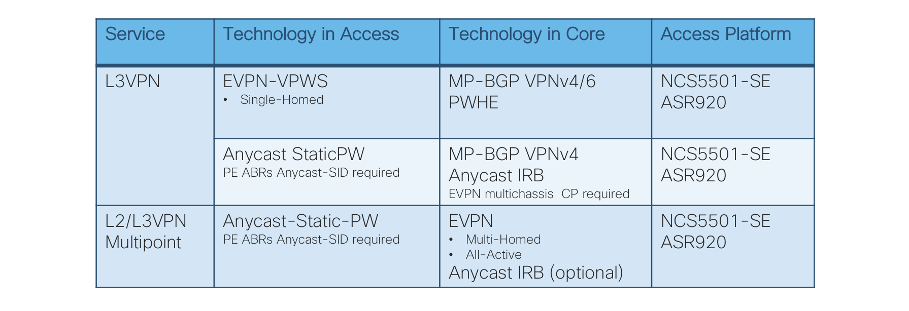
Figure 11: Hierarchical Services Table
L3VPN – Single-Homed EVPN-VPWS, MP-BGP VPNv4/6 with Pseudowire-Headend (PWHE)
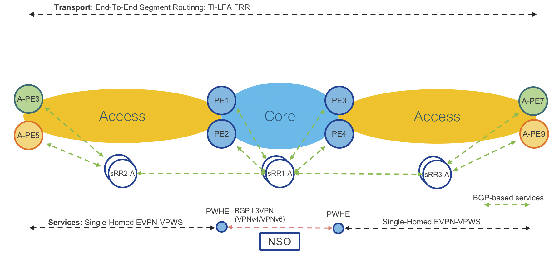
Figure 12: L3VPN – Single-Homed EVPN-VPWS, MP-BGP VPNv4/6 with Pseudowire-Headend (PWHE) Control Plane
Access Routers: Cisco NCS5501-SE IOS-XR or Cisco ASR920 IOS-XE
Operator: New EVPN-VPWS instance via CLI or NSO
Access Router: Path to PE Router is known via ACCESS-ISIS IGP.
Provider Edge Routers: Cisco ASR9000 IOS-XR
Operator: New EVPN-VPWS instance via CLI or NSO
Provider Edge Router: Path to Access Router is known via ACCESS-ISIS IGP.
Operator: New L3VPN instance (VPNv4/6) together with Pseudowire-Headend (PWHE) via CLI or NSO
Provider Edge Router: Path to remote PE is known via CORE-ISIS IGP.
Access Router Service Provisioning (IOS-XR):
VLAN based service configuration
l2vpn
 xconnect group evpn-vpws-l3vpn-PE1
  p2p L3VPN-VRF1
   interface TenGigE0/0/0/5.501
   neighbor evpn evi 13 target 501 source 501
   !
  !
 !
interface TenGigE0/0/0/5.501 l2transport
 encapsulation dot1q 501
 rewrite ingress tag pop 1 symmetric
Port based service configuration
l2vpn
 xconnect group evpn-vpws-l3vpn-PE1
 p2p odn-1
   interface TenGigE0/0/0/5
     neighbor evpn evi 13 target 502 source 502
   !
  !
 !
!
interface TenGigE0/0/0/5
  l2transport
Access Router Service Provisioning (IOS-XE):
VLAN based service configuration
l2vpn evpn instance 14 point-to-point
 vpws context evpn-pe4-pe1
  service target 501 source 501
  member GigabitEthernet0/0/1 service-instance 501
 !
interface GigabitEthernet0/0/1
 service instance 501 ethernet
  encapsulation dot1q 501
  rewrite ingress tag pop 1 symmetric
 !
Port based service configuration
l2vpn evpn instance 14 point-to-point
 vpws context evpn-pe4-pe1
  service target 501 source 501
  member GigabitEthernet0/0/1 service-instance 501
 !
interface GigabitEthernet0/0/1
 service instance 501 ethernet
  encapsulation default
Provider Edge Router Service Provisioning (IOS-XR):
VRF configuration
vrf L3VPN-ODNTE-VRF1
 address-family ipv4 unicast
  import route-target
   100:501
  !
  export route-target
   100:501
  !
 !
 address-family ipv6 unicast
  import
  route-target
   100:501
  !
  export
  route-target
   100:501
  !
 !
BGP configuration
router bgp 100
 vrf L3VPN-ODNTE-VRF1
  rd 100:501
  address-family ipv4 unicast
   redistribute connected
  !
  address-family ipv6 unicast
   redistribute connected
  !
 !
PWHE configuration
interface PW-Ether1
 vrf L3VPN-ODNTE-VRF1
 ipv4 address 10.13.1.1 255.255.255.0
 ipv6 address 1000:10:13::1/126
 attach generic-interface-list PWHE
!
EVPN VPWS configuration towards Access PE
l2vpn
 xconnect group evpn-vpws-l3vpn-A-PE3
  p2p L3VPN-ODNTE-VRF1
   interface PW-Ether1
   neighbor evpn evi 13 target 501 source 501
   !
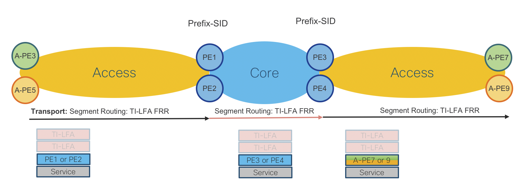
Figure 13: L3VPN – Single-Homed EVPN-VPWS, MP-BGP VPNv4/6 with Pseudowire-Headend (PWHE) Data Plane
L3VPN – Anycast Static Pseudowire (PW), MP-BGP VPNv4 with Anycast IRB
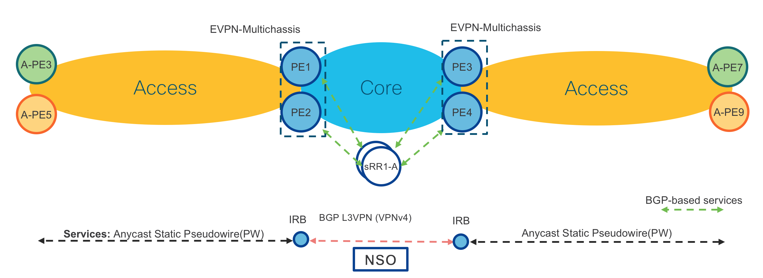
Figure 14: L3VPN – Anycast Static Pseudowire (PW), MP-BGP VPNv4 with Anycast IRB Control Plane
Access Routers: Cisco NCS5501-SE IOS-XR or Cisco ASR920 IOS-XE
Operator: New Static Pseudowire (PW) instance via CLI or NSO
Access Router: Path to PE Router is known via ACCESS-ISIS IGP.
Provider Edge Routers: Cisco ASR9000 IOS-XR (Same on both PE routers in same location PE1/2 and PE3/4)
Operator: New Static Pseudowire (PW) instance via CLI or NSO
Provider Edge Routers: Path to Access Router is known via ACCESS-ISIS IGP.
Operator: New L3VPN instance (VPNv4/6) together with Anycast IRB via CLI or NSO
Provider Edge Routers: Path to remote PEs is known via CORE-ISIS IGP.
Access Router Service Provisioning (IOS-XR):
VLAN based service configuration
l2vpn
 xconnect group Static-VPWS-PE12-H-L3VPN-AnyCast
  p2p L3VPN-VRF1
   interface TenGigE0/0/0/2.1
   neighbor ipv4 100.100.100.12 pw-id 5001
    mpls static label local 5001 remote 5001
    pw-class static-pw-h-l3vpn-class
   !
  !
interface TenGigE0/0/0/2.1 l2transport
 encapsulation dot1q 1
 rewrite ingress tag pop 1 symmetric
 !
!
l2vpn
 pw-class static-pw-h-l3vpn-class
  encapsulation mpls
   control-word
  !
Port based service configuration
l2vpn
 xconnect group Static-VPWS-PE12-H-L3VPN-AnyCast
  p2p L3VPN-VRF1
   interface TenGigE0/0/0/2
   neighbor ipv4 100.100.100.12 pw-id 5001
    mpls static label local 5001 remote 5001
    pw-class static-pw-h-l3vpn-class
   !
  !
interface TenGigE0/0/0/2
 l2transport
 !
!
l2vpn
 pw-class static-pw-h-l3vpn-class
  encapsulation mpls
   control-word
  !
Access Router Service Provisioning (IOS-XE):
VLAN based service configuration
interface GigabitEthernet0/0/5
 no ip address
 media-type auto-select
 negotiation auto
 service instance 1 ethernet
  encapsulation dot1q 1
  rewrite ingress tag pop 1 symmetric
  xconnect 100.100.100.12 4001 encapsulation mpls manual
   mpls label 4001 4001
   mpls control-word
 !
Port based service configuration
interface GigabitEthernet0/0/5
 no ip address
 media-type auto-select
 negotiation auto
 service instance 1 ethernet
  encapsulation default
  xconnect 100.100.100.12 4001 encapsulation mpls manual
   mpls label 4001 4001
   mpls control-word
 !
Provider Edge Routers Service Provisioning (IOS-XR):
cef adjacency route override rib
AnyCast Loopback configuration
interface Loopback100
 description Anycast
 ipv4 address 100.100.100.12 255.255.255.255
!
router isis ACCESS
 interface Loopback100
 address-family ipv4 unicast
  prefix-sid index 1012 n-flag-clear
L2VPN configuration
l2vpn
 bridge group Static-VPWS-H-L3VPN-IRB
  bridge-domain VRF1
   neighbor 100.0.1.50 pw-id 5001
    mpls static label local 5001 remote 5001
    pw-class static-pw-h-l3vpn-class
   !
   neighbor 100.0.1.51 pw-id 4001
    mpls static label local 4001 remote 4001
    pw-class static-pw-h-l3vpn-class
   !
   routed interface BVI1
    split-horizon group core
   !
   evi 12001
   !
  !
EVPN configuration
evpn
 evi 12001
 !
  advertise-mac
 !
 virtual neighbor 100.0.1.50 pw-id 5001
  ethernet-segment
   identifier type 0 12.00.00.00.00.00.50.00.01
Anycast IRB configuration
interface BVI1
 host-routing
 vrf L3VPN-AnyCast-ODNTE-VRF1
 ipv4 address 12.0.1.1 255.255.255.0
 mac-address 12.0.1
 load-interval 30
VRF configuration
vrf L3VPN-AnyCast-ODNTE-VRF1
 address-family ipv4 unicast
  import route-target
   100:10001
  !
  export route-target
   100:10001
  !
 !
!
BGP configuration
router bgp 100
 vrf L3VPN-AnyCast-ODNTE-VRF1
  rd auto
  address-family ipv4 unicast
   redistribute connected
  !
 !
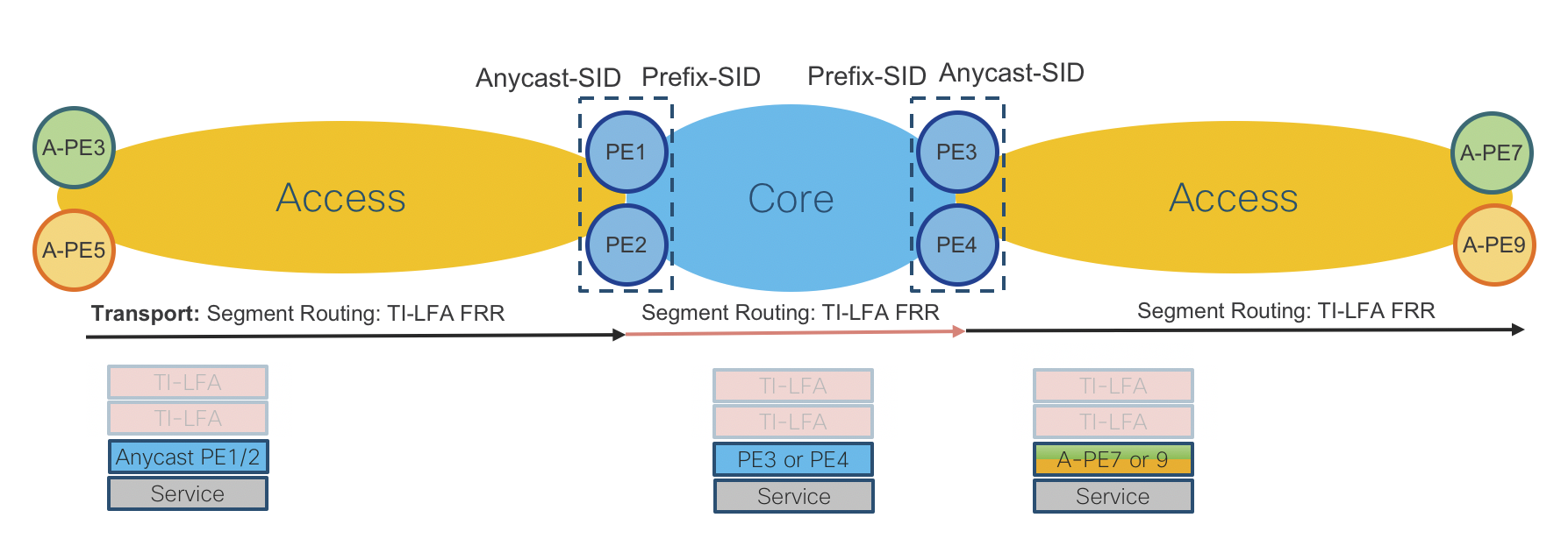
Figure 15: L3VPN – Anycast Static Pseudowire (PW), MP-BGP VPNv4/6 with Anycast IRB Datal Plane
L2/L3VPN – Anycast Static Pseudowire (PW), Multipoint EVPN with Anycast IRB
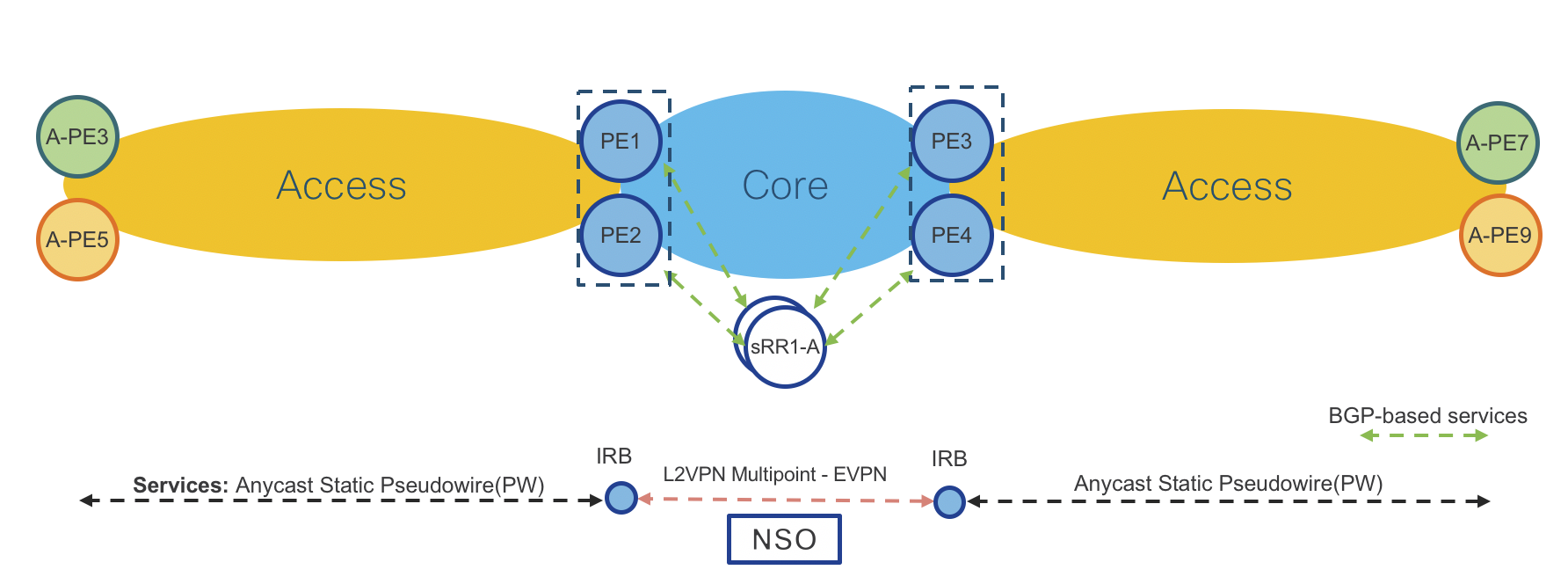
Figure 16: L2/L3VPN – Anycast Static Pseudowire (PW), Multipoint EVPN with Anycast IRB Control Plane
Access Routers: Cisco NCS5501-SE IOS-XR or Cisco ASR920 IOS-XE
Operator: New Static Pseudowire (PW) instance via CLI or NSO
Access Router: Path to PE Router is known via ACCESS-ISIS IGP.
Provider Edge Routers: Cisco ASR9000 IOS-XR (Same on both PE routers in same location PE1/2 and PE3/4)
Operator: New Static Pseudowire (PW) instance via CLI or NSO
Provider Edge Routers: Path to Access Router is known via ACCESS-ISIS IGP.
Operator: New L2VPN Multipoint EVPN instance together with Anycast IRB via CLI or NSO (Anycast IRB is optional when L2 and L3 is required in same service instance)
Provider Edge Routers: Path to remote PEs is known via CORE-ISIS IGP.
Please note that provisioning on Access and Provider Edge routers is same as in “L3VPN – Anycast Static Pseudowire (PW), MP-BGP VPNv4/6 with Anycast IRB”. In this use case there is BGP EVPN instead of MP-BGP VPNv4/6 in the core.
Access Router Service Provisioning (IOS-XR):
VLAN based service configuration
l2vpn
 xconnect group Static-VPWS-PE12-H-L3VPN-AnyCast
  p2p L3VPN-VRF1
   interface TenGigE0/0/0/2.1
   neighbor ipv4 100.100.100.12 pw-id 5001
    mpls static label local 5001 remote 5001
    pw-class static-pw-h-l3vpn-class
   !
  !
interface TenGigE0/0/0/2.1 l2transport
 encapsulation dot1q 1
 rewrite ingress tag pop 1 symmetric
!
l2vpn
 pw-class static-pw-h-l3vpn-class
  encapsulation mpls
   control-word
  !
Port based service configuration
l2vpn
 xconnect group Static-VPWS-PE12-H-L3VPN-AnyCast
  p2p L3VPN-VRF1
   interface TenGigE0/0/0/2
   neighbor ipv4 100.100.100.12 pw-id 5001
    mpls static label local 5001 remote 5001
    pw-class static-pw-h-l3vpn-class
   !
  !
!
interface TenGigE0/0/0/2
 l2transport
!
l2vpn
 pw-class static-pw-h-l3vpn-class
  encapsulation mpls
   control-word
Access Router Service Provisioning (IOS-XE):
VLAN based service configuration
interface GigabitEthernet0/0/5
 no ip address
 media-type auto-select
 negotiation auto
 service instance 1 ethernet
  encapsulation dot1q 1
  rewrite ingress tag pop 1 symmetric
  xconnect 100.100.100.12 4001 encapsulation mpls manual
   mpls label 4001 4001
   mpls control-word
 !
Port based service configuration
interface GigabitEthernet0/0/5
 no ip address
 media-type auto-select
 negotiation auto
 service instance 1 ethernet
  encapsulation default
  xconnect 100.100.100.12 4001 encapsulation mpls manual
   mpls label 4001 4001
   mpls control-word
 !
Provider Edge Routers Service Provisioning (IOS-XR):
cef adjacency route override rib
AnyCast Loopback configuration
interface Loopback100
 description Anycast
 ipv4 address 100.100.100.12 255.255.255.255
!
router isis ACCESS
 interface Loopback100
  address-family ipv4 unicast
   prefix-sid index 1012
L2VPN Configuration
l2vpn
 bridge group Static-VPWS-H-L3VPN-IRB
  bridge-domain VRF1
   neighbor 100.0.1.50 pw-id 5001
    mpls static label local 5001 remote 5001
    pw-class static-pw-h-l3vpn-class
   !
   neighbor 100.0.1.51 pw-id 4001
    mpls static label local 4001 remote 4001
    pw-class static-pw-h-l3vpn-class
   !
   routed interface BVI1
    split-horizon group core
   !
   evi 12001
   !
  !
EVPN configuration
evpn
 evi 12001
  !
  advertise-mac
  !
 !
 virtual neighbor 100.0.1.50 pw-id 5001
  ethernet-segment
   identifier type 0 12.00.00.00.00.00.50.00.01
Anycast IRB configuration
interface BVI1
 host-routing
 vrf L3VPN-AnyCast-ODNTE-VRF1
 ipv4 address 12.0.1.1 255.255.255.0
 mac-address 12.0.1
 load-interval 30
!
VRF configuration
vrf L3VPN-AnyCast-ODNTE-VRF1
 address-family ipv4 unicast
  import route-target
   100:10001
  !
  export route-target
   100:10001
  !
 !
!
BGP configuration
router bgp 100
 vrf L3VPN-AnyCast-ODNTE-VRF1
  rd auto
  address-family ipv4 unicast
   redistribute connected
  !
 !
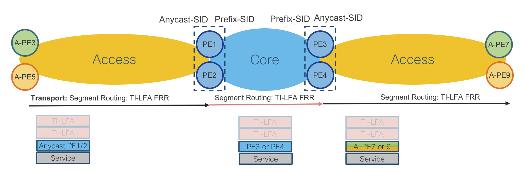
Figure 17: L2/L3VPN – Anycast Static Pseudowire (PW), Multipoint EVPN with Anycast IRB Data Plane
L2/L3VPN – EVPN Head-End Configuration
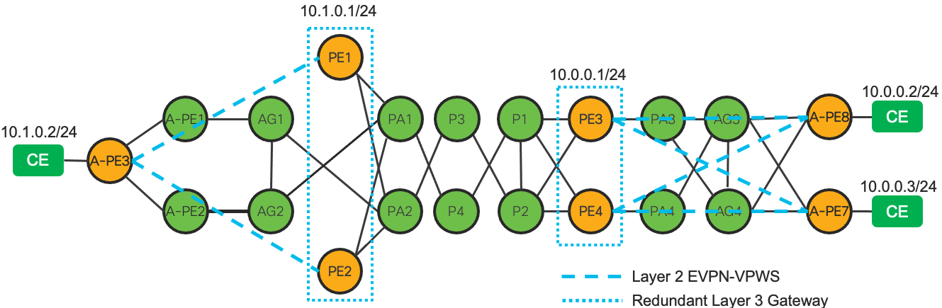 Figure 16: L2/L3VPN – EVPN Head-End
Access Routers: Cisco NCS 540, 5500, 560 IOS-XR
Operator: New EVPN-VPWS Pseudowire (PW) instance via CLI or NSO
Access Router: Path to PE Router is known via ACCESS-ISIS IGP.
Provider Edge Routers: Cisco ASR9000 IOS-XR (Same on both PE routers in same location PE1/2 and PE3/4)
Operator: New EVPN-VPWS Pseudowire (PW) instance via CLI or NSO
Provider Edge Routers: Path to Access Router is known via ACCESS-ISIS IGP.
Operator: New L2VPN Multipoint EVPN instance together with L3 PWHE interface via CLI or NSO
Provider Edge Routers: Path to remote PEs is known via CORE-ISIS IGP.
Access Router Service Provisioning (IOS-XR):
Interface Configuration
interface TenGigE0/0/0/5.2002 l2transport
 description EVPN-VPWS-PWHE-HEADEND
 encapsulation dot1q 2002
!
interface TenGigE0/0/0/5.2003 l2transport
 description EVPN-VPWS-PWHE-HEADEND
 encapsulation dot1q 2003
!
interface TenGigE0/0/0/5.2022 l2transport
 description EVPN-VPWS-PWHE-HEADEND
 encapsulation dot1q 2022
L2VPN Configuration In this example we use the NCS 540/5500 flexible xconnect service type to bundle multiple downstream interfaces into a single EVPN-VPWS to the EVPN Head End as a trunk. FXC can bundle VLANs from the same physical interface or different physical interfaces.
l2vpn
 flexible-xconnect-service vlan-unaware PWHE-Headend
  interface TenGigE0/0/0/5.2002
  interface TenGigE0/0/0/5.2003
  interface TenGigE0/0/0/5.2022
  neighbor evpn evi 2002 target 2002
Provider Edge Routers Service Provisioning (IOS-XR):
A similar configuration is found on all PE routers. Each pair of EVPN-HE routers share the same IP addresses and EVPN ESI on their PW-Ether2002 interfaces.
cef adjacency route override rib
EVPN-HE L3 Interface Configuration The following shows an example of both untagged and taggged interfaces. The same EVPN-VPWS is used as a trunk to carry traffic between Access and Head-End PE.
interface PW-Ether2002
 mtu 1518
 ipv4 address 100.9.2.1 255.255.255.252
 vrf L3VPN-AnyCast-ODNTE-VRF1
 mac-address 0.1111.1
 load-interval 30
 attach generic-interface-list PWHE
!
interface PW-Ether2002.2002
 vrf L3VPN-ODNTE-VRF1
 ipv4 address 11.4.1.1 255.255.255.0
 encapsulation dot1q 2002
!
interface PW-Ether2002.2003
 ipv4 address 11.5.1.1 255.255.255.0
 encapsulation dot1q 2003
EVPN Configuration
evpn
  interface PW-Ether2002
    ethernet-segment
    identifier type 0 99.99.99.99.99.01.00.00.00
    convergence
      nexthop-tracking
EVPN-VPWS to Access PE
xconnect group EVPN-HeadEnd
  p2p L3VPN-ODNTE-VRF11
   interface PW-Ether2002
   neighbor evpn evi 2002 target 2002 source 2002
VRF configuration
vrf L3VPN-AnyCast-ODNTE-VRF1
 address-family ipv4 unicast
  import route-target
   100:10001
  !
  export route-target
   100:10001
  !
L2/L3VPN – EVPN Centralized Gateway
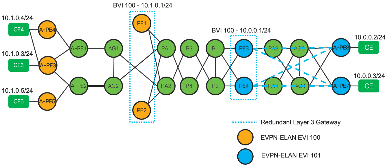
Figure 16: L2/L3VPN – EVPN Centralized Gateway
Access Routers: Cisco NCS 540, 5500, 560 IOS-XR
Operator: New EVPN-ELAN or ETREE instance via CLI or NSO
Access Router: Path to PE Router is known via ACCESS-ISIS IGP.
Provider Edge Routers: Cisco ASR9000 IOS-XR (Same on both PE routers in same location PE1/2 and PE3/4)
Operator: New EVPN-ELAN or ETREE instance via CLI or NSO
Provider Edge Routers: Path to Access Router is known via ACCESS-ISIS IGP.
Operator: New L3VPN Multipoint EVPN instance together with Anycast IRB interface via CLI or NSO
Provider Edge Routers: Path to remote PEs is known via CORE-ISIS IGP.
Access Router Service Provisioning (IOS-XR):
Interface Configuration
interface TenGigE0/0/0/5.2300 l2transport
 description EVPN-ELAN-CGW1-PE1/PE2
 encapsulation dot1q 2300
 rewrite ingress tag pop 1 symmetric
L2VPN and EVPN Configuration
l2vpn
 bridge group EVPN-ELAN-CGW1
  bridge-domain ELAN-CGW1
   interface TenGigE0/0/0/5.2300
   !
   evi 2400
   !
  !
evpn
 evi 2400
  advertise-mac
Provider Edge Routers Service Provisioning (IOS-XR):
A similar configuration is found on all PE routers. Each pair of EVPN-HE routers share the same IP addresses and MAC address providing a redundant Anycast IRB L3 gateway to L2 connected access devices.
EVPN CGW L3 BVI Interface Configuration In this example the interface is part of a core L3VPN, but the interface could reside in the global routing table (default VRF).
interface BVI100
 vrf cgw
 ipv4 address 100.10.1.1 255.255.0.0
 ipv6 address 100:10::1/64
 mac-address 0.dc1.dc2
L2VPN Configuration Note the access-evi configuration used for the EVI connected to the A-PE access routers.
l2vpn
 bridge group EVPN-ELAN-CGW1
  bridge-domain ELAN-CGW1
   access-evi 2400
   routed interface BVI100
EVPN Configuration In this case we are using ODN to create on-demand SR-TE policies between the core CGW PEs and access PEs.
evpn
 evi 2400
  bgp
   route-policy export cgw_srte_odn
   route-policy import cgw_srte_odn
  !
  advertise-mac
   bvi-mac
  !
 virtual access-evi
  ethernet-segment
   identifier type 0 00.00.ac.ce.55.00.e1.00.00
  !
  core-isolation-group 1
 !
!
VRF configuration
vrf cgw
 address-family ipv4 unicast
  import route-target
   10:10
  !
  export route-policy C1234
  export route-target
   10:10
  !
 !
 address-family ipv6 unicast
  export route-policy C1234
Ethernet CFM for L2VPN service assurance
Ethernet Connectivity Fault Management is an Ethernet OAM component used to validate end-to-end connectivity between service endpoints. Ethernet CFM is defined by two standards, 802.1ag and Y.1731. Within an SP network, Maintenance Domains are created based on service scope. Domains are typically separated by operator boundaries and may be nested but cannot overlap. Within each service, maintenance points can be created to verify bi-directional end to end connectivity. These are known as MEPs (Maintenance End-Point) and MIPs (Maintenance Intermediate Points). These maintenance points process CFM messages. A MEP is configured at service endpoints and has directionality where an “up” MEP faces the core of the network and a “down” MEP faces a CE device or NNI port. MIPs are optional and are created dynamically. Detailed information on Ethernet CFM configuration and operation can be found at https://www.cisco.com/c/en/us/td/docs/iosxr/ncs5500/interfaces/75x/configuration/guide/b-interfaces-hardware-component-cg-ncs5500-75x/m-configuring-ethernet-oam.html
Maintenance Domain configuration
A Maintenance Domain is defined by a unique name and associated level. The level can be 0-7. The numerical identifier usually corresponds to the scope of the MD, where 7 is associated with CE endpoints, 6 associated with PE devices connected to a CE. Additional levels may be required based on the topology and service boundaries which occur along the end-to-end service. In this example we only a single domain and utilize level 0 for all MEPs.
ethernet cfm
 domain EVPN-VPWS-PE3-PE8 level 0
MEP configuration for EVPN-VPWS services
For L2VPN xconnect services, each service must have a MEP created on the end PE device. There are two components to defining a MEP, first defining the Ethernet CFM “service” and then defining the MEP on the physical or logical interface participating in the L2VPN xconnect service. In the following configuration the xconnect group “EVPN-VPWS-ODN-PE3” and P2P EVPN VPWS service odn-8 are already defined. The Ethernet CFM service of “odn-8” does NOT have to match the xconnect service name. The MEP crosscheck defines a remote MEP to listen for Continuity Check messages from. It does not have to be the same as the local MEP defined on the physical sub-interface (103), but for P2P services it is best practice to make them identical. This configuration will send Ethernet CFM Continuity Check (CC) messages every 1 minute to verify end to end reachability.
L2VPN configuration
l2vpn
 xconnect group EVPN-VPWS-ODN-PE3
  p2p odn-8
   interface TenGigE0/0/0/23.8
   neighbor evpn evi 1318 target 8 source 8
   !
  !
 !
!
Physical sub-interface configuration
interface TenGigE0/0/0/23.8 l2transport
 encapsulation dot1q 8
 rewrite ingress tag pop 1 symmetric
 ethernet cfm
  mep domain EVPN-VPWS-PE3-PE8 service odn-8 mep-id 103
  !
 !
!
Ethernet CFM service configuration
ethernet cfm
 domain EVPN-VPWS-PE3-PE8
  service odn-8 xconnect group EVPN-VPWS-ODN-PE3 p2p odn-8
   mip auto-create all
   continuity-check interval 1m
   mep crosscheck
    mep-id 103
   !
   log crosscheck errors
   log continuity-check errors
   log continuity-check mep changes
  !
 !
!
Multicast Source Distribution using BGP Multicast AFI/SAFI
The Converged SDN Transport is inherently multi-domain to increase scalability. Multicast distribution trees built across the network using either native PIM, mLDP, or SR Tree-SID require the source be known to the receiver nodes to satisfy multicast’s RPF (Reverse Path Forwarding) check. The recommended way to distribute source addresses across the network is use the BGP IPv4/IPv6 multicast address family, utilizing the ABR nodes as inline RRs.
In the case of MVPN the sources are distributed inside the L3VPN as VPNV4 and VPNV6 prefixes.
Multicast BGP Configuration
router bgp 100
 !
 address-family ipv4 multicast
  redistribute connected route-policy mcast-sources
 !
 address-family ipv6 multicast
  redistribute connected route-policy mcast-sources
Multicast Profile 14 using mLDP and ODN L3VPN
In ths service example we will implement multicast delivery across the CST network using mLDP transport for multicast and SR-MPLS for unicast traffic. L3VPN SR paths will be dynamically created using ODN. Multicast profile 14 is the “Partitioned MDT - MLDP P2MP - BGP-AD - BGP C-Mcast Signaling” Using this profile each mVPN will use a dedicated P2MP tree, endpoints will be auto-discovered using NG-MVPN BGP NLRI, and customer multicast state such as source streams, PIM, and IGMP membership data will be signaled using BGP. Profile 14 is the recommended profile for high scale and utilizing label-switched multicast (LSM) across the core.
Please note that mLDP requires an IGP path to the source PE loopback address. The CST design utilizes a multi-domain approach which normally does not advertise IGP routes across domain boundaries. If mLDP is being utilized across domains, controlled redistribution should be used to advertise the source PE loopback addresses to receiver PEs
Multicast core configuration
The multicast “core” includes transit endpoints participating in mLDP only. See the mLDP core configuration section for details on end-to-end mLDP configuration.
Unicast L3VPN PE configuration
In order to complete an RPF check for SSM sources, unicast L3VPN configuration is required. Additionally the VRF must be defined under the BGP configuration with the NG-MVPN address families configured. In our use case we are utilizing ODN for creating the paths between L3VPN endpoints with a route-policy attached to the mVPN VRF to set a specific color on advertised routes.
ODN opaque ext-community set
extcommunity-set opaque MLDP
  1000
end-set
ODN route-policy
route-policy ODN-MVPN
  set extcommunity color MLDP
  pass
end-policy
Global L3VPN VRF definition
vrf VRF-MLDP
 address-family ipv4 unicast
  import route-target
   100:38
  !
  export route-policy ODN-MVPN
  export route-target
   100:38
  !
 !
 address-family ipv6 unicast
  import route-target
   100:38
  !
  export route-policy ODN-MVPN
  export route-target
   100:38
  !
 !
!
BGP configuration
router bgp 100
 vrf VRF-MLDP
  rd auto
  address-family ipv4 unicast
   redistribute connected
   redistribute static
  !
  address-family ipv6 unicast
   redistribute connected
   redistribute static
  !
  address-family ipv4 mvpn
  !
  address-family ipv6 mvpn
  !
 !
!
Multicast PE configuration
The multicast “edge” includes all endpoints connected to native multicast sources or receivers.
Define RPF policy
route-policy mldp-partitioned-p2mp
  set core-tree mldp-partitioned-p2mp
end-policy
!
Enable Multicast and define mVPN VRF
multicast-routing
 address-family ipv4
  interface Loopback0
   enable
  !
 !
 vrf VRF-MLDP
  address-family ipv4
   mdt source Loopback0
   rate-per-route
   interface all enable
   accounting per-prefix
   bgp auto-discovery mldp
   !
   mdt partitioned mldp ipv4 p2mp
   mdt data 100
  !
 !
!
Enable PIM for mVPN VRF In this instance there is an interface TenGigE0/0/0/23.2000 which is using PIM within the VRF
router pim
 address-family ipv4
  rp-address 100.0.1.50
 !
 vrf VRF-MLDP
  address-family ipv4
   rpf topology route-policy mldp-partitioned-p2mp
   mdt c-multicast-routing bgp
   !
   interface TenGigE0/0/0/23.2000
    enable
   !
  !
Enable IGMP for mVPN VRF interface To discover listeners for a specific group, enable IGMP on interfaces within the VRF. These interested receivers will be advertised via BGP to establish end to end P2MP trees from the source.
router igmp
 vrf VRF-MLDP
  interface TenGigE0/0/0/23.2001
  !
  version 3
 !
!
Multicast distribution using Tree-SID with static S,G Mapping
Tree-SID utilizes only Segment Routing to create and forward multicast traffic across an optimized tree. The Tree-SID tree is configured on the SR-PCE for deployment to the network. PCEP is used to instantiate the correct computed segments end to end. On the head-end source node,
Note: Tree-SID requires all nodes in the multicast distribution network to have connections to the same SR-PCE instances, please see the PCEP configuration section of the Implmentation Guide
Tree-SID SR-PCE Configuration
Endpoint Set Configuration
The P2MP endpoint sets are defined outside of the SR Tree-SID Policy configuration in order to be reusaable across multiple trees. This is a required step in the configuration of Tree-SID.
pce
 address ipv4 100.0.1.101
 timers
  reoptimization 600
 !
 segment-routing
  traffic-eng
   p2mp
     endpoint-set APE7-APE8
       ipv4 100.0.2.57
       ipv4 100.0.2.58
       !
   timers reoptimization 120
   timers cleanup 30
P2MP Tree-SID SR Policy Configuration
This configuration defines the Tree-SID P2MP SR Policy to be used across the network. Note the name of the Tree-SID must be unique across the netowrk and referenced explicitly on all source and receiver nodes. Within the policy configuration, supported constraints can be applied during path computation of the optimized P2MP tree. Note the source address must be specified and the MPLS label used must be within the SRLB for all nodes across the network.
pce
 segment-routing
   traffic-eng
     policy treesid-1
       source ipv4 100.0.0.1
       color 100 endpoint-set APE7-APE8
       treesid mpls 18600
       candidate-paths
        constraints
         affinity
          include-any
           color1
           !
          !
         !
        preference 100
         dynamic
         metric
          type igp
          !
         !
        !
Tree-SID Common Config on All Nodes
Segment Routing Local Block
While the SRLB config is covered elsewhere in this guide, it is recommended to set the values the same across the Tree-SID domain. The values shown are for demonstration only.
segment-routing
 local-block 18000 19000
 !
!
PCEP Configuration
Tree-SID relies on PCE initiated segments to the node, so a session to the PCE is required for all nodes in the domain.
segment-routing
 traffic-eng
  pcc
   source-address ipv4 100.0.2.53
   pce address ipv4 100.0.1.101
    precedence 200
   !
   pce address ipv4 100.0.2.101
    precedence 100
   !
   pce address ipv4 100.0.2.102
    precedence 100
   !
   report-all
   timers delegation-timeout 10
   timers deadtimer 60
   timers initiated state 15
   timers initiated orphan 10
  !
 !
!
Static Tree-SID Source Node Multicast Configuration
PIM Configuration
In this configuration a single S,G of 232.0.0.20 with a source of 104.14.1.2 is mapped to Tree-SID treesid-1 for distribution across the network.
router pim
 address-family ipv4
  interface Loopback0
   enable
  !
  interface Bundle-Ether111
   enable
  !
  interface Bundle-Ether112
   enable
  !
  interface TenGigE0/0/0/16
   enable
  !
  sr-p2mp-policy treesid-1
   static-group 232.0.0.20 104.14.1.2
  !
!
Multicast Routing Configuration
multicast-routing
  address-family ipv4
   interface all enable
   mdt static segment-routing
  !
  address-family ipv6
   mdt static segment-routing
  !
 !
Static Tree-SID Receiver Node Multicast Configuration
Global Routing Table Multicast
PIM Configuration
router pim
  address-family ipv4
   rp-address 100.0.0.1
  !
 !
!
On the router connected to the receivers, configure the address family to use the Tree-SID for static S,G mapping.
multicast-routing
 address-family ipv4
  mdt source Loopback0
  rate-per-route
  interface all enable
  static sr-policy Tree-SID-GRT
  mdt static segment-routing
  accounting per-prefix
 address-family ipv6
  mdt source Loopback0
  rate-per-route
  interface all enable
  static sr-policy Tree-SID-GRT
  mdt static segment-routing
  account per-prefix
 !
!
Multicast Routing Configuration
multicast-routing
  address-family ipv4
   interface all enable
   static sr-policy treesid-1
  !
  address-family ipv6
   static sr-policy treesid-1
  !
 !
mVPN Multicast Configuration
PIM Configuration
In this configuration, we are mapping the PIM RP to the TREESID source
router pim
 vrf TREESID
  address-family ipv4
   rp-address 100.0.0.1
  !
 !
!
Multicast Routing Configuration
On the PE connected to the receivers, within the VRF associated with the Tree-SID SR Policy, enable the Tree-SID for static mapping of S,G multicast.
multicast-routing
 vrf TREESID
  address-family ipv4
   interface all enable
   static sr-policy treesid-1
  !
  address-family ipv6
   static sr-policy treesid-1
  !
 !
Tree-SID Verification on PCE
You can view the end to end path using the “show pce lsp p2mp” command.
RP/0/RP0/CPU0:XTC-ACCESS1-PHY#show pce lsp p2mp
Wed Sep 2 19:31:50.745 UTC

Tree: treesid-1
  Label: 18600 Operational: up Admin: up
  Transition count: 1
  Uptime: 00:06:39 (since Wed Sep 02 19:25:11 UTC 2020)
  Source: 100.0.0.1
  Destinations: 100.0.2.53, 100.0.2.52
  Nodes:
    Node[0]: 100.0.2.3 (AG3)
    Role: Transit
    Hops:
      Incoming: 18600 CC-ID: 1
      Outgoing: 18600 CC-ID: 1 (10.23.253.1)
      Outgoing: 18600 CC-ID: 1 (10.23.252.0)
    Node[1]: 100.0.2.1 (PA3)
    Role: Transit
      Hops:
      Incoming: 18600 CC-ID: 2
      Outgoing: 18600 CC-ID: 2 (10.21.23.1)
    Node[2]: 100.0.0.3 (PE3)
    Role: Transit
    Hops:
      Incoming: 18600 CC-ID: 3
      Outgoing: 18600 CC-ID: 3 (10.3.21.1)
    Node[3]: 100.0.0.5 (P1)
    Role: Transit
    Hops:
      Incoming: 18600 CC-ID: 4
      Outgoing: 18600 CC-ID: 4 (10.3.5.0)
    Node[4]: 100.0.0.7 (P3)
    Role: Transit
    Hops:
      Incoming: 18600 CC-ID: 5
      Outgoing: 18600 CC-ID: 5 (10.5.7.0)
    Node[5]: 100.0.1.1 (NCS540-PA1)
    Role: Transit
    Hops:
      Incoming: 18600 CC-ID: 6
      Outgoing: 18600 CC-ID: 6 (10.1.7.1)
    Node[6]: 100.0.0.1 (PE1)
    Role: Ingress
    Hops:
      Incoming: 18600 CC-ID: 7
      Outgoing: 18600 CC-ID: 7 (10.1.11.1)
    Node[7]: 100.0.2.53 (A-PE8)
    Role: Egress
    Hops:
      Incoming: 18600 CC-ID: 8
    Node[8]: 100.0.2.52 (A-PE7)
    Role: Egress
    Hops:
      Incoming: 18600 CC-ID: 9
Multicast distribution using fully dynamic Tree-SID
In this example we will use dynamic source/receiver discovery using BGP and PCEP signaling to create the SR Tree-SID multicast distribution trees.
Please see https://www.cisco.com/c/en/us/td/docs/routers/asr9000/software/asr9k-r7-5/segment-routing/configuration/guide/b-segment-routing-cg-asr9000-75x/configure-sr-tree-sid.html for for full descriptions of configuration and optional parameters.
Note: There MUST be a BGP route to the source PE to satisfy the Tree-SID RPF check on receiver nodes. It is recommended for multicast to use the IPv4/IPv6 Multicast address family to distribute source information. Please see the section Multicast Source Distribution using BGP Multicast AFI/SAFI
PE BGP Configuration
The following is used to enable the IPv4/IPV6 MVPN AFI/SAFI globally. They address families are also added to the SvRR neighbor group.
router bgp 100
 address-family ipv4 mvpn
 !
 address-family ipv6 mvpn
 !
neighbor-group SvRR
  remote-as 100
  update-source Loopback0
  address-family ipv4 unicast
  !
  address-family vpnv4 unicast
   soft-reconfiguration inbound always
  !
  address-family vpnv6 unicast
   soft-reconfiguration inbound always
  !
  address-family ipv4 mvpn
   soft-reconfiguration inbound always
  !
  address-family ipv6 mvpn
   soft-reconfiguration inbound always
  !
  address-family l2vpn evpn
   soft-reconfiguration inbound always
  !
 !
PE Multicast Routing Configuration
Note the new configuration specific to SR auto-discovery and the color specified for the default MDT. The same configuration is used on both source and receiver PE routers.
div class="highlighter-rouge">
multicast-routing
 address-family ipv4
  interface Loopback0
   enable
  !
  mdt source Loopback0
  interface all enable
 !
 address-family ipv6
  interface all enable
 !
 vrf tree-sid
  address-family ipv4
   mdt source Loopback0
   interface all enable
   bgp auto-discovery segment-routing
   !
   mdt default segment-routing mpls color 80
  !
 !
PE PIM Configuration
The PIM configuration requires the following route-policy be defined.
route-policy sr-p2mp-core-tree
  set core-tree sr-p2mp
end-policy
router pim
 address-family ipv4
  interface Loopback0
   enable
  !
 !
 vrf tree-sid
  address-family ipv4
   rpf topology route-policy sr-p2mp-core-tree
   mdt c-multicast-routing bgp
   !
   multipath
   ssm range ssm
Hierarchical Services Examples
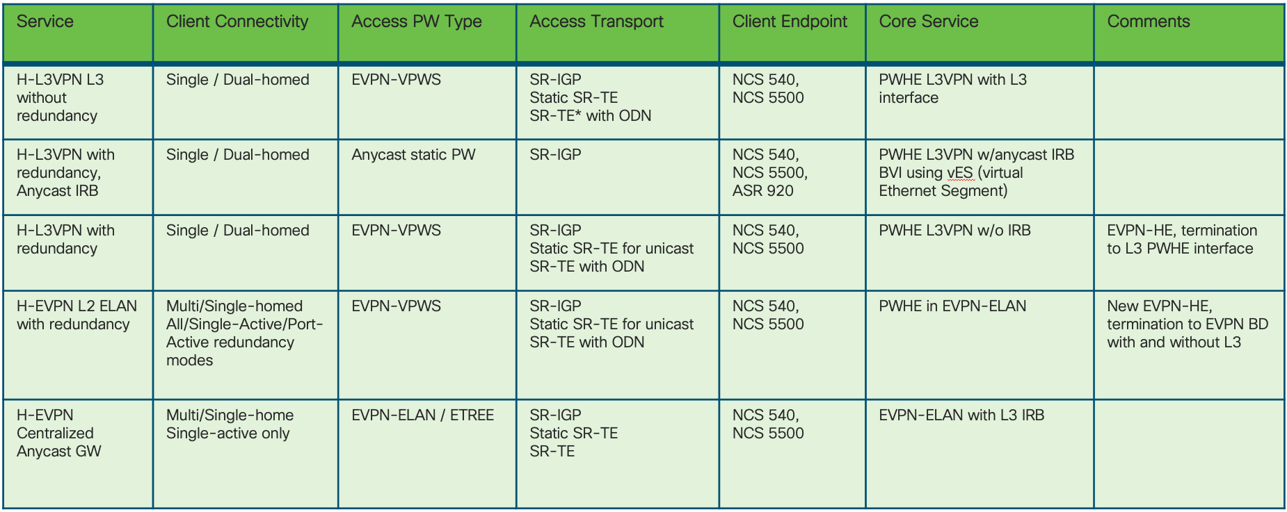
Figure 11: Hierarchical Services Table
L3VPN – Single-Homed EVPN-VPWS, MP-BGP VPNv4/6 with Pseudowire-Headend (PWHE)
Figure 12: L3VPN – Single-Homed EVPN-VPWS, MP-BGP VPNv4/6 with Pseudowire-Headend (PWHE) Control Plane
Access Routers: Cisco NCS 540, 5500, 560 IOS-XR, ASR 920 IOS-XE
Operator: New EVPN-VPWS instance via CLI or NSO
Access Router: Path to PE Router is known via ACCESS-ISIS IGP.
Provider Edge Routers: Cisco ASR9000 IOS-XR
Operator: New EVPN-VPWS instance via CLI or NSO
Provider Edge Router: Path to Access Router is known via ACCESS-ISIS IGP.
Operator: New L3VPN instance (VPNv4/6) together with Pseudowire-Headend (PWHE) via CLI or NSO
Provider Edge Router: Path to remote PE is known via CORE-ISIS IGP.
Access Router Service Provisioning (IOS-XR):
VLAN based service configuration
l2vpn
 xconnect group evpn-vpws-l3vpn-PE1
  p2p L3VPN-VRF1
   interface TenGigE0/0/0/5.501
   neighbor evpn evi 13 target 501 source 501
   !
  !
 !
interface TenGigE0/0/0/5.501 l2transport
 encapsulation dot1q 501
 rewrite ingress tag pop 1 symmetric
Port based service configuration
l2vpn
 xconnect group evpn-vpws-l3vpn-PE1
 p2p odn-1
  interface TenGigE0/0/0/5
   neighbor evpn evi 13 target 502 source 502
   !
  !
 !
!
interface TenGigE0/0/0/5
  l2transport
Access Router Service Provisioning (IOS-XE):
VLAN based service configuration
l2vpn evpn instance 14 point-to-point
 vpws context evpn-pe4-pe1
  service target 501 source 501
  member GigabitEthernet0/0/1 service-instance 501
 !
interface GigabitEthernet0/0/1
 service instance 501 ethernet
  encapsulation dot1q 501
  rewrite ingress tag pop 1 symmetric
 !
Port based service configuration
l2vpn evpn instance 14 point-to-point
 vpws context evpn-pe4-pe1
  service target 501 source 501
  member GigabitEthernet0/0/1 service-instance 501
 !
interface GigabitEthernet0/0/1
 service instance 501 ethernet
  encapsulation default
Provider Edge Router Service Provisioning (IOS-XR):
VRF configuration
vrf L3VPN-ODNTE-VRF1
 address-family ipv4 unicast
  import route-target
   100:501
  !
  export route-target
   100:501
  !
 !
 address-family ipv6 unicast
  import
  route-target
   100:501
  !
  export
  route-target
   100:501
  !
 !
BGP configuration
router bgp 100
 vrf L3VPN-ODNTE-VRF1
  rd 100:501
  address-family ipv4 unicast
   redistribute connected
  !
  address-family ipv6 unicast
   redistribute connected
  !
 !
PWHE configuration
interface PW-Ether1
 vrf L3VPN-ODNTE-VRF1
 ipv4 address 10.13.1.1 255.255.255.0
 ipv6 address 1000:10:13::1/126
 attach generic-interface-list PWHE
!
EVPN VPWS configuration towards Access PE
l2vpn
 xconnect group evpn-vpws-l3vpn-A-PE3
  p2p L3VPN-ODNTE-VRF1
   interface PW-Ether1
   neighbor evpn evi 13 target 501 source 501
   !
Figure 13: L3VPN – Single-Homed EVPN-VPWS, MP-BGP VPNv4/6 with Pseudowire-Headend (PWHE) Data Plane
L3VPN – Anycast Static Pseudowire (PW), MP-BGP VPNv4 with Anycast IRB
Figure 14: L3VPN – Anycast Static Pseudowire (PW), MP-BGP VPNv4 with Anycast IRB Control Plane
Access Routers: Cisco NCS5501-SE IOS-XR or Cisco ASR920 IOS-XE
Operator: New Static Pseudowire (PW) instance via CLI or NSO
Access Router: Path to PE Router is known via ACCESS-ISIS IGP.
Provider Edge Routers: Cisco ASR9000 IOS-XR (Same on both PE routers in same location PE1/2 and PE3/4)
Operator: New Static Pseudowire (PW) instance via CLI or NSO
Provider Edge Routers: Path to Access Router is known via ACCESS-ISIS IGP.
Operator: New L3VPN instance (VPNv4/6) together with Anycast IRB via CLI or NSO
Provider Edge Routers: Path to remote PEs is known via CORE-ISIS IGP.
Access Router Service Provisioning (IOS-XR):
VLAN based service configuration
l2vpn
 xconnect group Static-VPWS-PE12-H-L3VPN-AnyCast
  p2p L3VPN-VRF1
   interface TenGigE0/0/0/2.1
   neighbor ipv4 100.100.100.12 pw-id 5001
    mpls static label local 5001 remote 5001
    pw-class static-pw-h-l3vpn-class
   !
  !
interface TenGigE0/0/0/2.1 l2transport
 encapsulation dot1q 1
 rewrite ingress tag pop 1 symmetric
 !
!
l2vpn
 pw-class static-pw-h-l3vpn-class
  encapsulation mpls
   control-word
  !
Port based service configuration
l2vpn
 xconnect group Static-VPWS-PE12-H-L3VPN-AnyCast
  p2p L3VPN-VRF1
   interface TenGigE0/0/0/2
   neighbor ipv4 100.100.100.12 pw-id 5001
    mpls static label local 5001 remote 5001
    pw-class static-pw-h-l3vpn-class
   !
  !
interface TenGigE0/0/0/2
 l2transport
 !
!
l2vpn
 pw-class static-pw-h-l3vpn-class
  encapsulation mpls
   control-word
  !
Access Router Service Provisioning (IOS-XE):
VLAN based service configuration
interface GigabitEthernet0/0/5
 no ip address
 media-type auto-select
 negotiation auto
 service instance 1 ethernet
  encapsulation dot1q 1
  rewrite ingress tag pop 1 symmetric
  xconnect 100.100.100.12 4001 encapsulation mpls manual
   mpls label 4001 4001
   mpls control-word
 !
Port based service configuration
interface GigabitEthernet0/0/5
 no ip address
 media-type auto-select
 negotiation auto
 service instance 1 ethernet
  encapsulation default
  xconnect 100.100.100.12 4001 encapsulation mpls manual
   mpls label 4001 4001
   mpls control-word
 !
Provider Edge Routers Service Provisioning (IOS-XR):
cef adjacency route override rib
AnyCast Loopback configuration
interface Loopback100
 description Anycast
 ipv4 address 100.100.100.12 255.255.255.255
!
router isis ACCESS
 interface Loopback100
 address-family ipv4 unicast
  prefix-sid index 1012 n-flag-clear
L2VPN configuration
l2vpn
 bridge group Static-VPWS-H-L3VPN-IRB
  bridge-domain VRF1
   neighbor 100.0.1.50 pw-id 5001
    mpls static label local 5001 remote 5001
    pw-class static-pw-h-l3vpn-class
   !
   neighbor 100.0.1.51 pw-id 4001
    mpls static label local 4001 remote 4001
    pw-class static-pw-h-l3vpn-class
   !
   routed interface BVI1
    split-horizon group core
   !
   evi 12001
   !
  !
EVPN configuration
evpn
evi 12001
!
advertise-mac
!
virtual neighbor 100.0.1.50 pw-id 5001
ethernet-segment
identifier type 0 12.00.00.00.00.00.50.00.01
Anycast IRB configuration
interface BVI1
host-routing
vrf L3VPN-AnyCast-ODNTE-VRF1
ipv4 address 12.0.1.1 255.255.255.0
mac-address 12.0.1
load-interval 30
VRF configuration
vrf L3VPN-AnyCast-ODNTE-VRF1
address-family ipv4 unicast
import route-target
100:10001
!
export route-target
100:10001
!
!
!
BGP configuration
router bgp 100
vrf L3VPN-AnyCast-ODNTE-VRF1
rd auto
address-family ipv4 unicast
redistribute connected
!
!
Figure 15: L3VPN – Anycast Static Pseudowire (PW), MP-BGP VPNv4/6 with Anycast IRB Datal Plane
L2/L3VPN – Anycast Static Pseudowire (PW), Multipoint EVPN with Anycast IRB
Figure 16: L2/L3VPN – Anycast Static Pseudowire (PW), Multipoint EVPN with Anycast IRB Control Plane
Access Routers: Cisco NCS 540, 560, 5500 IOS-XR or Cisco ASR920 IOS-XE
Operator: New Static Pseudowire (PW) instance via CLI or NSO
Access Router: Path to PE Router is known via ACCESS-ISIS IGP.
Provider Edge Routers: Cisco ASR9000 IOS-XR (Same on both PE routers in same location PE1/2 and PE3/4)
Operator: New Static Pseudowire (PW) instance via CLI or NSO
Provider Edge Routers: Path to Access Router is known via ACCESS-ISIS IGP.
Operator: New L2VPN Multipoint EVPN instance together with Anycast IRB via CLI or NSO (Anycast IRB is optional when L2 and L3 is required in same service instance)
Provider Edge Routers: Path to remote PEs is known via CORE-ISIS IGP.
Please note that provisioning on Access and Provider Edge routers is same as in “L3VPN – Anycast Static Pseudowire (PW), MP-BGP VPNv4/6 with Anycast IRB”. In this use case there is BGP EVPN instead of MP-BGP VPNv4/6 in the core.
Access Router Service Provisioning (IOS-XR):
VLAN based service configuration
l2vpn
xconnect group Static-VPWS-PE12-H-L3VPN-AnyCast
p2p L3VPN-VRF1
interface TenGigE0/0/0/2.1
neighbor ipv4 100.100.100.12 pw-id 5001
mpls static label local 5001 remote 5001
pw-class static-pw-h-l3vpn-class
!
!
interface TenGigE0/0/0/2.1 l2transport
encapsulation dot1q 1
rewrite ingress tag pop 1 symmetric
!
l2vpn
pw-class static-pw-h-l3vpn-class
encapsulation mpls
control-word
!
Port based service configuration
l2vpn
xconnect group Static-VPWS-PE12-H-L3VPN-AnyCast
p2p L3VPN-VRF1
interface TenGigE0/0/0/2
neighbor ipv4 100.100.100.12 pw-id 5001
mpls static label local 5001 remote 5001
pw-class static-pw-h-l3vpn-class
!
!
!
interface TenGigE0/0/0/2
l2transport
!
l2vpn
pw-class static-pw-h-l3vpn-class
encapsulation mpls
control-word
Access Router Service Provisioning (IOS-XE):
VLAN based service configuration
interface GigabitEthernet0/0/5
no ip address
media-type auto-select
negotiation auto
service instance 1 ethernet
encapsulation dot1q 1
rewrite ingress tag pop 1 symmetric
xconnect 100.100.100.12 4001 encapsulation mpls manual
mpls label 4001 4001
mpls control-word
!
Port based service configuration
interface GigabitEthernet0/0/5
no ip address
media-type auto-select
negotiation auto
service instance 1 ethernet
encapsulation default
xconnect 100.100.100.12 4001 encapsulation mpls manual
mpls label 4001 4001
mpls control-word
!
Provider Edge Routers Service Provisioning (IOS-XR):
cef adjacency route override rib
AnyCast Loopback configuration
interface Loopback100
description Anycast
ipv4 address 100.100.100.12 255.255.255.255
!
router isis ACCESS
interface Loopback100
address-family ipv4 unicast
prefix-sid index 1012
L2VPN Configuration
l2vpn
bridge group Static-VPWS-H-L3VPN-IRB
bridge-domain VRF1
neighbor 100.0.1.50 pw-id 5001
mpls static label local 5001 remote 5001
pw-class static-pw-h-l3vpn-class
!
neighbor 100.0.1.51 pw-id 4001
mpls static label local 4001 remote 4001
pw-class static-pw-h-l3vpn-class
!
routed interface BVI1
split-horizon group core
!
evi 12001
!
!
EVPN configuration
evpn
evi 12001
!
advertise-mac
!
!
virtual neighbor 100.0.1.50 pw-id 5001
ethernet-segment
identifier type 0 12.00.00.00.00.00.50.00.01
Anycast IRB configuration
interface BVI1
host-routing
vrf L3VPN-AnyCast-ODNTE-VRF1
ipv4 address 12.0.1.1 255.255.255.0
mac-address 12.0.1
load-interval 30
!
VRF configuration
vrf L3VPN-AnyCast-ODNTE-VRF1
address-family ipv4 unicast
import route-target
100:10001
!
export route-target
100:10001
!
!
!
BGP configuration
router bgp 100
vrf L3VPN-AnyCast-ODNTE-VRF1
rd auto
address-family ipv4 unicast
redistribute connected
!
!
Figure 17: L2/L3VPN – Anycast Static Pseudowire (PW), Multipoint EVPN with Anycast IRB Data Plane
Remote PHY CIN Implementation
Summary
Detail can be found in the CST high-level design guide for design decisions, this section will provide sample configurations.
Sample QoS Policies
The following are usable policies but policies should be tailored for specific network deployments.
Class maps
Class maps are used within a policy map to match packet criteria for further treatment
class-map match-any match-ef-exp5
description High priority, EF
match dscp 46
match mpls experimental topmost 5
end-class-map
!
class-map match-any match-cs5-exp4
description Second highest priority
match dscp 40
match mpls experimental topmost 4
end-class-map
!
class-map match-any match-video-cs4-exp2
description Video
match dscp 32
match mpls experimental topmost 2
end-class-map
!
class-map match-any match-cs6-exp6
description Highest priority control-plane traffic
match dscp cs6
match mpls experimental topmost 6
end-class-map
!
class-map match-any match-qos-group-1
match qos-group 1
end-class-map
!
class-map match-any match-qos-group-2
match qos-group 2
end-class-map
!
class-map match-any match-qos-group-3
match qos-group 3
end-class-map
!
class-map match-any match-qos-group-6
match qos-group 3
end-class-map
!
class-map match-any match-traffic-class-1
description "Match highest priority traffic-class 1"
match traffic-class 1
end-class-map
!
class-map match-any match-traffic-class-2
description "Match high priority traffic-class 2"
match traffic-class 2
end-class-map
!
class-map match-any match-traffic-class-3
description "Match medium traffic-class 3"
match traffic-class 3
end-class-map
!
class-map match-any match-traffic-class-6
description "Match video traffic-class 6"
match traffic-class 6
end-class-map
RPD and DPIC interface policy maps
These are applied to all interfaces connected to cBR-8 DPIC and RPD devices.
Note: Egress queueing maps are not supported on L3 BVI interfaces
RPD/DPIC ingress classifier policy map
policy-map rpd-dpic-ingress-classifier
class match-cs6-exp6
set traffic-class 1
set qos-group 1
!
class match-ef-exp5
set traffic-class 2
set qos-group 2
!
class match-cs5-exp4
set traffic-class 3
set qos-group 3
!
class match-video-cs4-exp2
set traffic-class 6
set qos-group 6
!
class class-default
set traffic-class 0
set dscp 0
set qos-group 0
!
end-policy-map
!
P2P RPD and DPIC egress queueing policy map
policy-map rpd-dpic-egress-queuing
class match-traffic-class-1
priority level 1
queue-limit 500 us
!
class match-traffic-class-2
priority level 2
queue-limit 100 us
!
class match-traffic-class-3
priority level 3
queue-limit 500 us
!
class match-traffic-class-6
priority level 6
queue-limit 500 us
!
class class-default
queue-limit 250 ms
!
end-policy-map
!
Core QoS
Please see the general QoS section for core-facing QoS configuration
CIN Timing Configuration
Please see the G.8275.1 and G.8275.2 timing configuration guides in this document for configuring G.8275.2 on downstream RPD interfaces. Starting in CST 4.0, PTP can be enabled on either physical L3 interfaces or BVI interfaces. PTP is not supported on Bundle Ethernet interfaces.
Starting in CST 4.0 it is recommended to use G.8275.1 end to end across the timing domain, and utilize G.8275.2 on specific interfaces using the PTP Multi-Profile configuration outlined in this document. G.8275.1 allows the use of Bundle Ethernet interfaces within the CIN network.
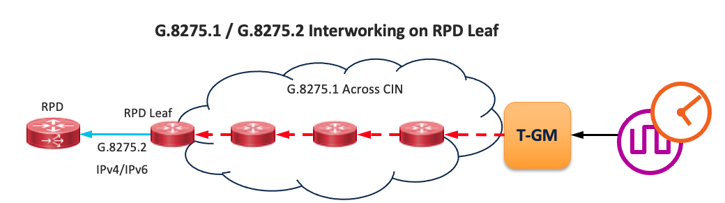
PTP Messaging Rates
The following are recommended rate values to be used for PTP messaging.
| PTP variable | IOS-XR configuration value | IOS-XE value |
|---|---|---|
| Announce Interval | 1 | 1 |
| Announce Timeout | 5 | 5 |
| Sync Frequency | 16 | -4 |
| Delay Request Frequency | 16 | -4 |
Example CBR-8 RPD DTI Profile
ptp r-dti 4
profile G.8275.2
ptp-domain 60
clock-port 1
clock source ip 192.168.3.1
sync interval -4
announce timeout 5
delay-req interval -4
Multicast configuration
Summary
We present two different configuration options based on either native multicast deployment or the use of a L3VPN to carry Remote PHY traffic. The L3VPN option shown uses Label Switched Multicast profile 14 (partitioned mLDP) however profile 6 could also be utilized.
Global multicast configuration - Native multicast
On CIN aggregation nodes all interfaces should have multicast enabled.
multicast-routing
address-family ipv4
interface all enable
!
address-family ipv6
interface all enable
enable
!
Global multicast configuration - LSM using profile 14
On CIN aggregation nodes all interfaces should have multicast enabled.
vrf VRF-MLDP
address-family ipv4
mdt source Loopback0
rate-per-route
interface all enable
accounting per-prefix
bgp auto-discovery mldp
!
mdt partitioned mldp ipv4 p2mp
mdt data 100
!
!
PIM configuration - Native multicast
PIM should be enabled for IPv4/IPv6 on all core facing interfaces
router pim
address-family ipv4
interface Loopback0
enable
!
interface TenGigE0/0/0/6
enable
!
interface TenGigE0/0/0/7
enable
!
!
PIM configuration - LSM using profile 14
The PIM configuration is utilized even though no PIM neighbors may be connected.
route-policy mldp-partitioned-p2mp
set core-tree mldp-partitioned-p2mp
end-policy
!
router pim
address-family ipv4
interface Loopback0
enable
vrf rphy-vrf
address-family ipv4
rpf topology route-policy mldp-partitioned-p2mp
mdt c-multicast-routing bgp
!
!
IGMPv3/MLDv2 configuration - Native multicast
Interfaces connected to RPD and DPIC interfaces should have IGMPv3 and MLDv2 enabled
router igmp
interface BVI100
version 3
!
interface TenGigE0/0/0/25
version 3
!
!
router mld
interface BVI100
version 2
interface TenGigE0/0/0/25
version 3
!
!
IGMPv3/MLDv2 configuration - LSM profile 14
Interfaces connected to RPD and DPIC interfaces should have IGMPv3 and MLDv2 enabled as needed
router igmp
vrf rphy-vrf
interface BVI101
version 3
!
interface TenGigE0/0/0/15
!
!
!
router mld
vrf rphy-vrf
interface TenGigE0/0/0/15
version 2
!
!
!
IGMPv3 / MLDv2 snooping profile configuration (BVI aggregation)
In order to limit L2 multicast replication for specific groups to only interfaces with interested receivers, IGMP and MLD snooping must be enabled.
igmp snooping profile igmp-snoop-1
!
mld snooping profile mld-snoop-1
!
RPD DHCPv4/v6 relay configuration
In order for RPDs to self-provision DHCP relay must be enabled on all RPD-facing L3 interfaces. In IOS-XR the DHCP relay configuration is done in its own configuration context without any configuration on the interface itself.
Native IP / Default VRF
dhcp ipv4
profile rpd-dhcpv4 relay
helper-address vrf default 10.0.2.3
!
interface BVI100 relay profile rpd-dhcpv4
!
dhcp ipv6
profile rpd-dhcpv6 relay
helper-address vrf default 2001:10:0:2::3
iana-route-add
source-interface BVI100
!
interface BVI100 relay profile rpd-dhcpv6
RPHY L3VPN
In this example it is assumed the DHCP server exists within the rphy-vrf VRF, if it does not then additional routing may be necessary to forward packets between VRFs.
dhcp ipv4
vrf rphy-vrf relay profile rpd-dhcpv4-vrf
profile rpd-dhcpv4-vrf relay
helper-address vrf rphy-vrf 10.0.2.3
relay information option allow-untrusted
!
inner-cos 5
outer-cos 5
interface BVI101 relay profile rpd-dhcpv4-vrf
interface TenGigE0/0/0/15 relay profile rpd-dhcpv4-vrf
!
cBR-8 DPIC interface configuration without Link HA
Without link HA the DPIC port is configured as a normal physical interface
interface TenGigE0/0/0/25
description .. Connected to cbr8 port te1/1/0
service-policy input rpd-dpic-ingress-classifier
service-policy output rpd-dpic-egress-queuing
ipv4 address 4.4.9.101 255.255.255.0
ipv6 address 2001:4:4:9::101/64
carrier-delay up 0 down 0
load-interval 30
cBR-8 DPIC interface configuration with Link HA
When using Link HA faster convergence is achieved when each DPIC interface is placed into a BVI with a statically assigned MAC address. Each DPIC interface is placed into a separate bridge-domain with a unique BVI L3 interface. The same MAC address should be utilized on all BVI interfaces. Convergence using BVI interfaces is <50ms, L3 physical interfaces is 1-2s.
Even DPIC port CIN interface configuration
interface TenGigE0/0/0/25
description "Connected to cBR8 port Te1/1/0"
lldp
!
carrier-delay up 0 down 0
load-interval 30
l2transport
!
!
l2vpn
bridge group cbr8
bridge-domain port-ha-0
interface TenGigE0/0/0/25
!
routed interface BVI500
!
!
!
interface BVI500
description "BVI for cBR8 port HA, requires static MAC"
service-policy input rpd-dpic-ingress-classifier
ipv4 address 4.4.9.101 255.255.255.0
ipv6 address 2001:4:4:9::101/64
mac-address 8a.9698.64
load-interval 30
!
Odd DPIC port CIN interface configuration
interface TenGigE0/0/0/26
description "Connected to cBR8 port Te1/1/1"
lldp
!
carrier-delay up 0 down 0
load-interval 30
l2transport
!
!
l2vpn
bridge group cbr8
bridge-domain port-ha-1
interface TenGigE0/0/0/26
!
routed interface BVI501
!
!
!
interface BVI501
description "BVI for cBR8 port HA, requires static MAC"
service-policy input rpd-dpic-ingress-classifier
ipv4 address 4.4.9.101 255.255.255.0
ipv6 address 2001:4:4:9::101/64
mac-address 8a.9698.64
load-interval 30
!
cBR-8 Digital PIC Interface Configuration
interface TenGigE0/0/0/25
description .. Connected to cbr8 port te1/1/0
service-policy input rpd-dpic-ingress-classifier
service-policy output rpd-dpic-egress-queuing
ipv4 address 4.4.9.101 255.255.255.0
ipv6 address 2001:4:4:9::101/64
carrier-delay up 0 down 0
load-interval 30
RPD interface configuration
P2P L3
In this example the interface has PTP enabled towards the RPD
interface TeGigE0/0/0/15
description To RPD-1
mtu 9200
ptp
profile g82752_master_v4
!
service-policy input rpd-dpic-ingress-classifier
service-policy output rpd-dpic-egress-queuing
ipv4 address 192.168.2.0 255.255.255.254
ipv6 address 2001:192:168:2::0/127
ipv6 enable
!
BVI
l2vpn
bridge group rpd
bridge-domain rpd-1
mld snooping profile mld-snoop-1
igmp snooping profile igmp-snoop-1
interface TenGigE0/0/0/15
!
interface TenGigE0/0/0/16
!
interface TenGigE0/0/0/17
!
routed interface BVI100
!
!
!
!
!
interface BVI100
description ... to downstream RPD hosts
ptp
profile g82752_master_v4
!
service-policy input rpd-dpic-ingress-classifier
ipv4 address 192.168.2.1 255.255.255.0
ipv6 address 2001:192:168:2::1/64
ipv6 enable
!
RPD/DPIC agg device IS-IS configuration
The standard IS-IS configuration should be used on all core interfaces with the addition of specifying all DPIC and RPD connected as IS-IS passive interfaces. Using passive interfaces is preferred over redistributing connected routes. This configuration is needed for reachability between DPIC and RPDs across the CIN network.
router isis ACCESS
interface TenGigE0/0/0/25
passive
address-family ipv4 unicast
!
address-family ipv6 unicast
Additional configuration for L3VPN Design
Global VRF Configuration
This configuration is required on all DPIC and RPD connected routers as well as ancillary elements communicating with Remote PHY elements
vrf rphy-vrf
address-family ipv4 unicast
import route-target
100:5000
!
export route-target
100:5000
!
!
address-family ipv6 unicast
import route-target
100:5000
!
export route-target
100:5000
!
!
BGP Configuration
This configuration is required on all DPIC and RPD connected routers as well as ancillary elements communicating with Remote PHY elements
router bgp 100
vrf rphy-vrf
rd auto
address-family ipv4 unicast
label mode per-vrf
redistribute connected
!
address-family ipv6 unicast
label mode per-vrf
redistribute connected
!
address-family ipv4 mvpn
!
address-family ipv6 mvpn
!
!
cBR-8 Segment Routing Configuration
In the CST 4.0 design we introduce Segment Routing on the cBR-8. Configuration of SR on the cBR-8 follows the configuration on other IOS-XE devices. This configuration guide covers only IGP SR-MPLS, and not SR-TE configuration. This allows the cBR-8 to send/receive traffic from other SR-MPLS nodes within the same IGP domain. The cBR-8 can also utilize these paths for BGP next-hop resolution for Global Routing Table (GRT) and BSOD L2VPN/L3VPN services. The following example configuration is for the SUP connection via IS-IS to the provider network, SR is not supported on DPIC interfaces.
IS-IS Configuration
router isis access
net 49.0001.0010.0000.0013.00
is-type level-2-only
router-id Loopback0
authentication mode md5 level-1
authentication mode md5 level-2
authentication key-chain ISIS-KEY level-1
authentication key-chain ISIS-KEY level-2
metric-style wide
fast-flood 10
set-overload-bit on-startup 120
max-lsp-lifetime 65535
lsp-refresh-interval 65000
spf-interval 5 50 200
prc-interval 5 50 200
lsp-gen-interval 5 5 200
log-adjacency-changes
segment-routing mpls
segment-routing prefix-sid-map advertise-local
fast-reroute per-prefix level-2 all
fast-reroute ti-lfa level-2
passive-interface Bundle1
passive-interface Loopback0
!
address-family ipv6
multi-topology
exit-address-family
mpls traffic-eng router-id Loopback0
mpls traffic-eng level-2
Segment Routing Configuration
segment-routing mpls
!
set-attributes
address-family ipv4
sr-label-preferred
exit-address-family
!
global-block 16000 32000
!
connected-prefix-sid-map
address-family ipv4
1.0.0.13/32 index 213 range 1
exit-address-family
!
!
Interface Configuration
The connected prefix map is used to advetise the Loopback0 interface as a SR Node SID.
interface TenGigabitEthernet4/1/6
description "Connected to PE4 TenGigE 0/0/0/19"
ip address 4.1.6.1 255.255.255.0
ip router isis access
load-interval 30
cdp enable
ipv6 address 2001:4:1:6::1/64
ipv6 router isis access
mpls ip
mpls traffic-eng tunnels
isis circuit-type level-2-only
isis network point-to-point
isis authentication mode md5
isis authentication key-chain ISIS-NCS
isis csnp-interval 10 level-1
isis csnp-interval 10 level-2
hold-queue 400 in
Cloud Native Broadband Network Gateway (cnBNG)
See the high level design for more information on Cisco cnBNG solution. The following covers the configuration of the User Plane router, in this case an ASR 9000 router.
The following configuring is used for a deployment using IPoE subscriber sessions. The configuration of some external elements such as the RADIUS authentication server are outside the scope of this document. The cnBNG control plane software deployment is also out of scope for this document, please see the cnBNG documentation located at:
interface Loopback10
ipv6 enable
!
cnbng-nal location 0/RSP0/CPU0
hostidentifier ASR9k-1
!! up-server ip should be the ip of UP interface which will be used as source for SCi communication
up-server ipv4 113.1.1.1 vrf default
!! cp-server ip is the IP of UDP Proxy configuration
cp-server primary ipv4 113.1.1.2
auto-loopback vrf default
interface Loopback10
primary-address 1.1.1.1
!
!
!! retry-count specifies how many times UP should retry the connection with CP before declaring CP as dead
cp-association retry-count 10
secondary-address-update enable
!
dhcp ipv4
profile cnbng_v4 cnbng
!
interface Bundle-Ether12.101 cnbng profile cnbng_v4
!
dhcp ipv6
profile cnbng_v6 cnbng
!
interface Bundle-Ether12.101 cnbng profile cnbng_v6
!
interface Bundle-Ether12.101
ipv4 point-to-point
ipv4 unnumbered Loopback10
ipv6 address 2001::1/64
ipv6 enable
load-interval 30
encapsulation dot1q 101
ipsubscriber
ipv4 l2-connected
initiator dhcp
!
ipv6 l2-connected
initiator dhcp
Pseudowire Headend Configuration In this use case subscribers are tunneled to the User Plane using EVPN-VPWS from a remote access node.
interface PW-Ether2000
mtu 1518
ipv4 address 17.1.1.1 255.255.255.0
attach generic-interface-list PWHE
!
interface PW-Ether2000.2000
ipv4 address 182.168.10.1 255.255.255.252
ipv6 address 2000:111:1::1:1/64
ipv6 enable
service-policy type control subscriber IPoE_PWHE1
encapsulation dot1q 2000
ipsubscriber ipv4 l2-connected
initiator dhcp
!
ipsubscriber ipv6 l2-connected
initiator dhcp
!
!
dhcp ipv6
profile ipoev6_proxy proxy
helper-address vrf default 2001:12:3::2
source-interface Loopback0
!
interface PW-Ether2000.2000 proxy profile ipoev6_proxy
!
!
l2vpn
logging
pseudowire
!
xconnect group pwhe-bng
p2p pwhe-bng1
interface PW-Ether2000
neighbor evpn evi 40 target 900 source 900
Model-Driven Telemetry Configuration
Summary
This is not an exhaustive list of IOS-XR model-driven telemetry sensor paths, but gives some basic paths used to monitor a Converged SDN Transport deployment. Each sensor path may have its own cadence of collection and transmission, but it’s recommended to not use values less than 60s when using many sensor paths.
Device inventory and monitoring
| Metric | Sensor path |
|---|---|
| Full inventory via OpenConfig model | openconfig-platform:components |
| NCS 540/5500 NPU resources | cisco-ios-xr-fretta-bcm-dpa-hw-resources-oper/dpa/stats/nodes/node/hw-resources-datas/hw-resources-data |
| Optics information | cisco-ios-xr-controller-optics-oper:optics-oper/optics-ports/optics-port/optics-info |
| System uptime | cisco-ios-xr-shellutil-oper:system-time/uptime |
| System CPU utilization | cisco-ios-xr-wdsysmon-fd-oper:system-monitoring/cpu-utilization |
Interface Data
| Metric | Sensor path |
|---|---|
| Interface optics state | Cisco-IOS-XR-controller-optics-oper:optics-oper/optics-ports/optics-port/optics-info/transport-admin-state |
| OpenConfig interface stats | openconfig-interfaces:interfaces |
| Interface data rates, based on load-interval | Cisco-IOS-XR-infra-statsd-oper:infra-statistics/interfaces/interface/data-rate |
| Interface counters similar to “show int” | Cisco-IOS-XR-infra-statsd-oper:infra-statistics/interfaces/interface/latest/generic-counters |
| Full interface information | Cisco-IOS-XR-pfi-im-cmd-oper:interfaces/interface-xr/interface |
| Interface stats | Cisco-IOS-XR-pfi-im-cmd-oper:interfaces/interface-xr/interface/interface-statistics |
| Subset of interface stats | Cisco-IOS-XR-pfi-im-cmd-oper:interfaces/interface-xr/interface/interface-statistics/basic-interface-stats |
LLDP Monitoring
| Metric | Sensor path |
|---|---|
| All LLDP Info | Cisco-IOS-XR-ethernet-lldp-oper:lldp |
| LLDP neighbor info | Cisco-IOS-XR-ethernet-lldp-oper:lldp/nodes/node/neighbors |
| LLDP statistics | Cisco-IOS-XR-ethernet-lldp-oper:lldp/nodes/node/statistics |
Aggregate bundle information (use interface models for interface counters)
| Metric | Sensor path |
|---|---|
| OpenConfig LAG information | openconfig-if-aggregate:aggregate |
| OpenConfig LAG state only | openconfig-if-aggregate:aggregate/state |
| OpenConfig LACP information | openconfig-lacp:lacp |
| Cisco full bundle information | Cisco-IOS-XR-bundlemgr-oper:bundles |
| Cisco BFD over Bundle stats | Cisco-IOS-XR-bundlemgr-oper:bundle-information/bfd-counters |
| Cisco Bundle data | Cisco-IOS-XR-bundlemgr-oper:lacp-bundles/bundles/bundle/data |
| Cisco Bundle member data | Cisco-IOS-XR-bundlemgr-oper:lacp-bundles/bundles/bundle/members |
PTP and SyncE Information
| Metric | Sensor path |
|---|---|
| PTP servo status | Cisco-IOS-XR-ptp-oper:ptp/platform/servo/device-status |
| PTP servo statistics | Cisco-IOS-XR-ptp-oper:ptp/platform/servo |
| PTP foreign master information | Cisco-IOS-XR-ptp-oper:ptp/interface-foreign-masters |
| PTP interface counters, key is interface name | Cisco-IOS-XR-ptp-oper:ptp/interface-packet-counters |
| Frequency sync info | Cisco-IOS-XR-freqsync-oper:frequency-synchronization/summary/frequency-summary |
| SyncE interface information, key is interface name | Cisco-IOS-XR-freqsync-oper:frequency-synchronization/interface-datas/interface-data |
BGP Information
| Metric | Sensor path | |
|---|---|---|
| BGP established neighbor count across all AF | Cisco-IOS-XR-ipv4-bgp-oper:bgp/instances/instance/instance-active/vrfs/vrf/process-info/global/established-neighbors-count-total | |
| BGP total neighbor count | Cisco-IOS-XR-ipv4-bgp-oper:bgp/instances/instance/instance-active/vrfs/vrf/process-info/global/neighbors-count-total | |
| BGP prefix SID count | Cisco-IOS-XR-ipv4-bgp-oper:bgp/instances/instance/instance-active/vrfs/vrf/process-info/global/prefix-sid-label-index-count | |
| BGP total VRF count including default VRF | Cisco-IOS-XR-ipv4-bgp-oper:process-info/ipv4-bgp-oper:global/ipv4-bgp-oper:total-vrf-count | |
| BGP convergence | Cisco-IOS-XR-ipv4-bgp-oper:bgp/instances/instance/instance-active/default-vrf/afs/af/af-process-info/performance-statistics/global/ | has-converged |
| BGP IPv4 route count | Cisco-IOS-XR-ip-rib-ipv4-oper:rib/rib-table-ids/rib-table-id/summary-protos/summary-proto/rtype-bgp-ext/active-routes-count | |
| OpenConfig BGP information | openconfig-bgp:bgp | |
| OpenConfig BGP neighbor info only | openconfig-bgp:bgp/neighbors |
IS-IS Information
| Metric | Sensor path |
|---|---|
| IS-IS neighbor info | sensor-path Cisco-IOS-XR-clns-isis-oper:isis/instances/instance/neighbors |
| IS-IS interface info | sensor-path Cisco-IOS-XR-clns-isis-oper:isis/instances/instance/levels/interfaces |
| IS-IS adj information | sensor-path Cisco-IOS-XR-clns-isis-oper:isis/instances/instance/levels/adjacencies |
| IS-IS neighbor summary | sensor-path Cisco-IOS-XR-clns-isis-oper:isis/instances/instance/neighbor-summaries |
| IS-IS node count | Cisco-IOS-XR-clns-isis-oper:isis/instances/instance/topologies/topology/topology-levels/topology-level/topology-summary/router-node-count/reachable-node-count |
| IS-IS adj state | Cisco-IOS-XR-clns-isis-oper:isis/instances/instance/levels/level/adjacencies/adjacency/adjacency-state |
| IS-IS neighbor count | Cisco-IOS-XR-clns-isis-oper:isis/instances/instance/neighbor-summaries/neighbor-summary/level2-neighbors/neighbor-up-count |
| IS-IS total route count | Cisco-IOS-XR-ip-rib-ipv4-oper:rib/rib-table-ids/rib-table-id/summary-protos/summary-proto/rtype-isis-l2/active-routes-count |
Routing protocol RIB information
| Metric | Sensor path |
|---|---|
| IS-IS L1 Info | Cisco-IOS-XR-ip-rib-ipv4-oper:rib/rib-table-ids/rib-table-id/summary-protos/summary-proto/rtype-isis-l1 |
| IS-IS L2 Info | Cisco-IOS-XR-ip-rib-ipv4-oper:rib/rib-table-ids/rib-table-id/summary-protos/summary-proto/rtype-isis-l2 |
| IS-IS Summary | Cisco-IOS-XR-ip-rib-ipv4-oper:rib/rib-table-ids/rib-table-id/summary-protos/summary-proto/rtype-isis-sum |
| Total route count per protocol | Cisco-IOS-XR-ip-rib-ipv4-oper:rib/rib-table-ids/rib-table-id/summary-protos/summary-proto/proto-route-count |
| IPv6 IS-IS L1 info | Cisco-IOS-XR-ip-rib-ipv6-oper:rib/rib-table-ids/rib-table-id/summary-protos/summary-proto/rtype-isis-l1 |
| IPv6 IS-IS L2 info | Cisco-IOS-XR-ip-rib-ipv6-oper:rib/rib-table-ids/rib-table-id/summary-protos/summary-proto/rtype-isis-l2 |
| IPv6 IS-IS summary | Cisco-IOS-XR-ip-rib-ipv6-oper:rib/rib-table-ids/rib-table-id/summary-protos/summary-proto/rtype-isis-sum |
| IPv6 total route count per protocol | Cisco-IOS-XR-ip-rib-ipv6-oper:rib/rib-table-ids/rib-table-id/summary-protos/summary-proto/proto-route-count |
BGP RIB information
It is not recommended to monitor these paths using MDT with large tables
| Metric | Sensor path |
|---|---|
| OC BGP RIB | openconfig-rib-bgp:bgp-rib |
| IPv4 BGP RIB | Cisco-IOS-XR-ip-rib-ipv4-oper:rib/rib-table-ids/rib-table-id/summary-protos/summary-proto/rtype-bgp-ext |
| IPv4 BGP RIB | Cisco-IOS-XR-ip-rib-ipv4-oper:rib/rib-table-ids/rib-table-id/summary-protos/summary-proto/rtype-bgp-int |
| IPv6 BGP RIB | Cisco-IOS-XR-ip-rib-ipv6-oper:rib/rib-table-ids/rib-table-id/summary-protos/summary-proto/rtype-bgp-ext |
| IPv6 BGP RIB | Cisco-IOS-XR-ip-rib-ipv6-oper:rib/rib-table-ids/rib-table-id/summary-protos/summary-proto/rtype-bgp-int |
Routing policy Information
| Metric | Sensor path |
|---|---|
| Routing policy information | Cisco-IOS-XR-policy-repository-oper:routing-policy/policies |
Ethernet CFM
| Metric | Sensor path |
|---|---|
| Ethernet CFM MA/MEP information | Cisco-IOS-XR-ethernet-cfm-oper:cfm/global/maintenance-points/maintenance-point |
EVPN Information
| Metric | Sensor path |
|---|---|
| EVPN information | Cisco-IOS-XR-l2vpn-oper:l2vpn-forwarding/nodes/node/l2fib-summary/evpn-summary |
| Total EVPN | Cisco-IOS-XR-l2vpn-oper:l2vpn-forwarding/nodes/node/l2fib-summary/evpn-summary/total-count |
| EVPN total ES entries | Cisco-IOS-XR-evpn-oper:evpn/active/summary/es-entries |
| EVPN local Eth Auto Discovery routes | Cisco-IOS-XR-evpn-oper:evpn/active/summary/local-ead-routes |
| EVPN remote Eth Auto Discovery routes | Cisco-IOS-XR-evpn-oper:evpn/active/summary/remote-ead-routes |
| EVPN summary | Cisco-IOS-XR-evpn-oper:evpn/nodes/node/summary |
| EVPN neighbor information | Cisco-IOS-XR-evpn-oper:evpn/nodes/node/evi-detail/evi-children/neighbors/neighbor |
| EVPN EAD information | Cisco-IOS-XR-evpn-oper:evpn/nodes/node/evi-detail/evi-children/ethernet-auto-discoveries/ethernet-auto-discovery |
Per-Interface QoS Statistics Information
| Metric | Sensor path |
|---|---|
| Input stats | Cisco-IOS-XR-qos-ma-oper:qos/nodes/node/policy-map/interface-table/interface/input/statistics/ |
| General QoS Stats | Cisco-IOS-XR-qos-ma-oper:qos/nodes/node/policy-map/interface-table/interface/input/statistics/class-stats/general-stats |
| Per-queue stats | Cisco-IOS-XR-qos-ma-oper:qos/nodes/node/policy-map/interface-table/interface/input/statistics/class-stats/queue-stats-array |
| General service policy information, keys are policy name and interface applied | Cisco-IOS-XR-qos-ma-oper:qos/interface-table/interface/input/service-policy-names |
Per-Policy, Per-Interface, Per-Class statistics
See sensor path name for detailed information on data leafs
| Metric | Sensor path |
|---|---|
| Per-class matched data rate | Cisco-IOS-XR-qos-ma-oper:qos/nodes/node/policy-map/interface-table/interface/input/service-policy-names/service-policy-instance/statistics/class-stats/general-stats/match-data-rate |
| Pre-policy Matched Bytes | Cisco-IOS-XR-qos-ma-oper:qos/nodes/node/policy-map/interface-table/interface/input/service-policy-names/service-policy-instance/statistics/class-stats/general-stats/pre-policy-matched-bytes |
| Pre-policy Matched Packets | Cisco-IOS-XR-qos-ma-oper:qos/nodes/node/policy-map/interface-table/interface/input/service-policy-names/service-policy-instance/statistics/class-stats/general-stats/pre-policy-matched-packets |
| Dropped bytes per class | Cisco-IOS-XR-qos-ma-oper:qos/nodes/node/policy-map/interface-table/interface/input/service-policy-names/service-policy-instance/statistics/class-stats/general-stats/total-drop-bytes |
| Total dropped packets | Cisco-IOS-XR-qos-ma-oper:qos/nodes/node/policy-map/interface-table/interface/input/service-policy-names/service-policy-instance/statistics/class-stats/general-stats/total-drop-packets |
| Drop rate | Cisco-IOS-XR-qos-ma-oper:qos/nodes/node/policy-map/interface-table/interface/input/service-policy-names/service-policy-instance/statistics/class-stats/general-stats/total-drop-rate |
| Transmit rate | Cisco-IOS-XR-qos-ma-oper:qos/nodes/node/policy-map/interface-table/interface/input/service-policy-names/service-policy-instance/statistics/class-stats/general-stats/total-transmit-rate |
| Per-class transmitted bytes | Cisco-IOS-XR-qos-ma-oper:qos/nodes/node/policy-map/interface-table/interface/input/service-policy-names/service-policy-instance/statistics/class-stats/general-stats/transmit-bytes |
| Queue current length | Cisco-IOS-XR-qos-ma-oper:qos/nodes/node/policy-map/interface-table/interface/input/service-policy-names/service-policy-instance/statistics/class-stats/queue-stats-array/queue-instance-length/value |
| Queue max length units | Cisco-IOS-XR-qos-ma-oper:qos/nodes/node/policy-map/interface-table/interface/input/service-policy-names/service-policy-instance/statistics/class-stats/queue-stats-array/queue-max-length/unit |
| Queue max length value | Cisco-IOS-XR-qos-ma-oper:qos/nodes/node/policy-map/interface-table/interface/input/service-policy-names/service-policy-instance/statistics/class-stats/queue-stats-array/queue-max-length/value |
| WRED dropped bytes | Cisco-IOS-XR-qos-ma-oper:qos/nodes/node/policy-map/interface-table/interface/input/service-policy-names/service-policy-instance/statistics/class-stats/queue-stats-array/random-drop-bytes |
| WRED dropped packets | Cisco-IOS-XR-qos-ma-oper:qos/nodes/node/policy-map/interface-table/interface/input/service-policy-names/service-policy-instance/statistics/class-stats/queue-stats-array/random-drop-packets |
| Tail dropped packets per class | Cisco-IOS-XR-qos-ma-oper:qos/nodes/node/policy-map/interface-table/interface/input/service-policy-names/service-policy-instance/statistics/class-stats/queue-stats-array/tail-drop-bytes |
| Tail dropped bytes per class | Cisco-IOS-XR-qos-ma-oper:qos/nodes/node/policy-map/interface-table/interface/input/service-policy-names/service-policy-instance/statistics/class-stats/queue-stats-array/tail-drop-packets |
| State per policy instance | Cisco-IOS-XR-qos-ma-oper:qos/nodes/node/policy-map/interface-table/interface/input/service-policy-names/service-policy-instance/statistics/class-stats/shared-queue-id |
L2VPN Information
| Metric | Sensor path |
|---|---|
| L2VPN general forwarding information including EVPN and Bridge Domains | Cisco-IOS-XR-l2vpn-oper:l2vpn-forwarding/nodes/node/l2fib-summary |
| Bridge domain information | Cisco-IOS-XR-l2vpn-oper:l2vpn-forwarding/nodes/node/l2fib-summary/bridge-domain-summary |
| Total BDs active | Cisco-IOS-XR-l2vpn-oper:l2vpn-forwarding/nodes/node/l2fib-summary/bridge-domain-summary/bridge-domain-count |
| Total BDs using EVPN | Cisco-IOS-XR-l2vpn-oper:l2vpn-forwarding/nodes/node/l2fib-summary/bridge-domain-summary/bridge-domain-with-evpn-enabled |
| Total MAC count (Local+remote) | Cisco-IOS-XR-l2vpn-oper:l2vpn-forwarding/nodes/node/l2fib-summary/mac-summary/mac-count |
| L2VPN xconnect Forwarding information | Cisco-IOS-XR-l2vpn-oper:l2vpn-forwarding/nodes/node/l2fib-summary/xconnect-summary |
| Xconnect total count | Cisco-IOS-XR-l2vpn-oper:l2vpnv2/active/xconnect-summary/number-xconnects |
| Xconnect down count | Cisco-IOS-XR-l2vpn-oper:l2vpnv2/active/xconnect-summary/number-xconnects-down |
| Xconnect up count | Cisco-IOS-XR-l2vpn-oper:l2vpnv2/active/xconnect-summary/number-xconnects-up |
| Xconnect unresolved | Cisco-IOS-XR-l2vpn-oper:l2vpnv2/active/xconnect-summary/number-xconnects-unresolved |
| Xconnect with down attachment circuits | Cisco-IOS-XR-l2vpn-oper:l2vpn-forwarding/nodes/node/l2fib-summary/xconnect-summary/ac-down-count-l2vpn |
| Per-xconnect detailed information including state | xconnect group and name are keys: Cisco-IOS-XR-l2vpn-oper:l2vpnv2/active/xconnects/xconnect |
| L2VPN bridge domain specific information, will have the BD name as a key | Cisco-IOS-XR-l2vpn-oper:l2vpn-forwarding/nodes/node/l2fib-bridge-domains/l2fib-bridge-domain |
| L2VPN EVPN IPv4 MAC/IP information | Cisco-IOS-XR-l2vpn-oper:l2vpn-forwarding/nodes/node/l2fib-evpn-ip4macs |
| L2VPN EVPN IPv6 MAC/IP information | Cisco-IOS-XR-l2vpn-oper:l2vpn-forwarding/nodes/node/l2fib-evpn-ip6macs |
L3VPN Information
| Metric | Sensor path |
|---|---|
| Per-VRF detailed information | Cisco-IOS-XR-mpls-vpn-oper:l3vpn/vrfs/vrf |
SR-PCE PCC and SR Policy Information
| Metric | Sensor path |
|---|---|
| PCC to PCE peer information | Cisco-IOS-XR-infra-xtc-agent-oper:pcc/peers |
| SR policy summary info | Cisco-IOS-XR-infra-xtc-agent-oper:xtc/policy-summary |
| Specific SR policy information | Cisco-IOS-XR-infra-xtc-agent-oper:xtc/policy-summary/configured-down-policy-count |
| Specific SR policy information | Cisco-IOS-XR-infra-xtc-agent-oper:xtc/policy-summary/configured-total-policy-count |
| Specific SR policy information | Cisco-IOS-XR-infra-xtc-agent-oper:xtc/policy-summary/configured-up-policy-count |
| SR policy information, key is SR policy name | Cisco-IOS-XR-infra-xtc-agent-oper:xtc/policies/policy |
| SR policy forwarding info including packet and byte stats per candidate path, key is policy name and candidate path | Cisco-IOS-XR-infra-xtc-agent-oper:xtc/policy-forwardings |
MPLS performance measurement
| Metric | Sensor path |
|---|---|
| Summary info | Cisco-IOS-XR-perf-meas-oper:performance-measurement/nodes/node/summary |
| Interface stats for delay measurements | Cisco-IOS-XR-perf-meas-oper:performance-measurement/nodes/node/summary/delay-summary/interface-delay-summary/delay-transport-counters/generic-counters |
| Interface stats for loss measurement | Cisco-IOS-XR-perf-meas-oper:performance-measurement/nodes/node/summary/loss-summary/interface-loss-summary |
| Parent interface oper data sensor path | Cisco-IOS-XR-perf-meas-oper:performance-measurement/nodes/node/interfaces |
| Delay values for each probe measurement | Cisco-IOS-XR-perf-meas-oper:performance-measurement/nodes/node/interfaces/delay/interface-last-probes |
| Delay values aggregated at computation interval | Cisco-IOS-XR-perf-meas-oper:performance-measurement/nodes/node/interfaces/delay/interface-last-aggregations |
| Delay values aggregated at advertisement interval | Cisco-IOS-XR-perf-meas-oper:performance-measurement/nodes/node/interfaces/delay/interface-last-advertisements |
| SR Policy measurement for delay and liveness | Cisco-IOS-XR-perf-meas-oper:performance-measurement/nodes/node/sr-policies |
| SR Policy delay | Cisco-IOS-XR-perf-meas-oper:performance-measurement/nodes/node/sr-policies/sr-policy-delay |
| SR Policy liveness detection | Cisco-IOS-XR-perf-meas-oper:performance-measurement/nodes/node/sr-policies/sr-policy-liveness |
| SR Policy PM Details | Cisco-IOS-XR-perf-meas-oper:performance-measurement/nodes/node/sr-policies/sr-policy-details |
mLDP Information
| Metric | Sensor path |
|---|---|
| mLDP LSP count | Cisco-IOS-XR-mpls-ldp-mldp-oper:mpls-mldp/active/default-context/context/lsp-count |
| mLDP peer count | Cisco-IOS-XR-mpls-ldp-mldp-oper:mpls-mldp/active/default-context/context/peer-count |
| mLDP database info, where specific LSP information is stored | Cisco-IOS-XR-mpls-ldp-mldp-oper:mpls-mldp/active/default-context/databases/database |
ACL Information
| Metric | Sensor path |
|---|---|
| Details on ACL resource consumption | Cisco-IOS-XR-ipv4-acl-oper:ipv4-acl-and-prefix-list/oor/access-list-summary/details/current-configured-ac-es |
| OpenConfig full ACL information | openconfig-acl:acl |
Leave a Comment