
Secure SD-WAN Core Design
Introduction
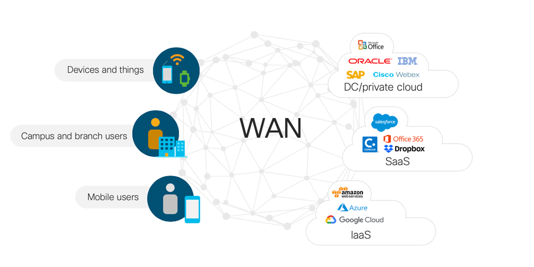
Today’s Enterprise and Public Sector networks are highly distributed, spanning branch and campus, data center, multiple public clouds and the Internet. The WAN is the heart of the network, connecting users and applications in a secure and automated network that spans the globe.
Important Trends in WAN Design
The Enterprise and Public Sector WAN is rapidly evolving in response to numerous business trends and technological innovations. These include:
- Cloud: Organizations of all sizes are recognizing the many benefits of SaaS/IaaS applications which means that more and more workloads are running across multiple clouds, including AWS, Google, Microsoft Azure and others. The WAN core must be able to accomodate shifting traffic patterns as more traffic goes to the Cloud.
- SD-WAN and Internet-as-a-Transport: For years, Enterprises have relied on private MPLS-based services for security, segmentation, and SLAs for an Enterprise WAN. Unfortunately, these services are often expensive and slow to turn up. The Internet–quick to turn up, universally available and relatively inexpensive– was not an option for business connectivity because it’s not secure or differentiated. SD-WAN bridged the gap by providing security and application-awareness as overlays, enabling businesses to leverage the Internet for transport. While small and mid-size businesses may be able to run their entire WAN with SD-WAN, larger and/or global organization will still need a WAN Core which can co-exist and integrate with SD-WAN as an overlay as needed.
- Dark Fiber: The Internet is not the only new option for transport. Providers are increasingly making unusued or underutilized fiber infrastructure available to businesses with massive bandwidth needs, either in the form of an entire fiber or a wavelength (“lambda”) on a partially used fiber. Unlike traditional transport services whose costs scale with utilization, dark fiber offers a relatively low, known fixed cost over long lease periods (e.g. 10 years). For businesses that need very low latency, high security or customization (or all three) and have the resources to light it up, dark fiber is an attractive option for WAN Core designs.
- Ethernet Services: Another possibility for businesses who need high bandwidth is an Ethernet service such as Ethernet Private Line (EPL). In this case, the business configures and manages routing while the provider has responsibility for optical and L2 connectivity. While offering large amounts of bandwidth at a low cost, Ethernet services may not have the same SLAs as a traditional MPLS service. Also, EPL may not be available everywhere. On a global level, there are many providers competing to offer low-cost EPL. In certain regions or countries, there may be few (if any) EPL options.
- Co-lo Connectivity: Co-location providers (e.g. Equinix) provide central data centers with direct connections to data centers, Iaas/SaaS cloud providers, Internet peering and users. These globally distributed Colos are often connected with high-bandwidth EPL circuits. Enterprises looking to build a WAN Core can host their routers in the Colo and use the Colo’s EPL service to make the routers think they are directly connected to each other. Because Colo providers often connect to Iaas and Saas providers like AWS, Google and Microsoft, businesses can connect directly to those services in the Colo as well.
- 100 Gigabit Ethernet: The rise of high-density, low-power fixed and modular 100 Gigabit Ethernet platforms like Cisco’s NCS 5500 series routers has reduced the barriers to 100G adoption and expanded the design choices for Enterprise WAN Core.
Who Needs Secure SD-WAN Core
The Secure SD-WAN Core Design is a Cisco IOS-XR-based architecture for large enterprises, government agencies, public utilities, military and defense agencies, large commerical organizations and anyone else whose business requirements cannot be met by the SD-WAN design alone. This includes customers who need:
- Full control of the end-to-end network
- Cost-optimized transport
- Self-determined QOS SLA
- Rapid service delivery
- High bandwidth, high density links (100 GE) in the backbone
- High availability (targeting 5 9s)
- Large scale routing metrics and tables
- Rich traffic-engineering capabilities
- Line-rate encryption using MACSec
The typical WAN Core customer may have:
- many locations and services
- high volume of traffic
- SP-like requirements (e.g. multi-tenant segmentation)
Some of the customers who have deployed WAN Cores include:

- Financial institutions
- Government agencies
- Military and Defense
- Healthcare
- Higher Education
- Utilities
Design Goals
The SD-WAN Core is aligned with the following design goals.
Network Simplification
Simplicity scales; complexity does not. By reducing the amount of state and number of protocols in the core, operators can deploy networks that are easier to scale and simpler to operate. The SD-WAN Core simplifies the control plane by using Segment Routing, a source-routing architecture that provides complete control over forwarding paths while reducing the amount of state in the network.
Segment Routing eliminates the need for LDP by folding label distribution into the IGP itself. Eliminating the LDP protocol reduces the amount of state and computation required of the routers. It also completely removes the issue of LDP-IGP synchronization and associated troubleshooting.
Segment Routing also provides superior convergence on failure for best-path and traffic-engineered paths without targeted LDP and/or the complicated state associated with RSVP-TE.
Simplification also enables automation: the simpler and more uniform the design, the easier it is to automate.
Network Availability
Network availability has always been a key design goal of core networks. Availability can be built into the physical topology as well as the control plane. SD-WAN Core design uses multiple methods to increase network availability:
- Scale Out: A large, scaled-up router with complex internal HA mechanisms has a large blast radius and is at greater risk of complex gray failures that are difficult to detect and troubleshoot. To improve availability, the WAN core design offers a horizontally scalable option with fixed form factor devices. Horizontal scaling is sometimes referred to as “scaling out.”
- Multi-planar Topologies: One way to improve availability is to isolate failure domains. In networks, this can take the form of parallel layers in the networks called “planes.” Planes are designed so that failure in one does not impact traffic in another. Planes can be configured to back each other up or to remain completely isolated on failure, according to the business requirement. The SD-WAN Core design uses Segment Routing Flexible Algorithm (Flex-Algo) to slice planes in the network.
- Simple, Fast Convergence: The SD-WAN Core uses the simple, built-in mechanisms of Segment Routing Transport Independent Loop Free Alternative (TI-LFA) for sub-50 milisecond convergence for all traffic types. It provides full coverage, is topology independent and does not require extra protocols like targeted LDP or RSVP-TE.
Security
Enterprise and public sector traffic must be protected as it travels the globe from branch to campus to public and private clouds. While IPSec offers secure L3 encryption, it is a CPU-intensive operation that can be challenging at scale. The SD-WAN Core design keeps traffic safe by pervasively deploying MACSec, an IEEE standard for point-to-point encryption at Layer 2. Because it operates at Layer 2, MACSec ensures that your traffic is protected even across EPL circuits. Line-rate support for MACSec is an option for all the platforms in the design.
For traffic isolation, network segmentation can be extended across the network using BGP L2/L3/E-VPN services.
Customization
One of the reasons organizations take on the challenge of managing their own WAN core is that they need full control of how traffic transits the core.
When considering traffic engineering, it can be useful to distinguish between proactive and reactive traffic engineering. Proactive TE constructs paths and even reserves bandwidth in advance. In networks that are well-engineered with sufficient capacity, proactive TE is often not necessary and adds needless complexity. Reactive (or “tactical”) TE, on the other hand, reacts to real-time conditions in the network like congestion and temporarily re-directs traffic onto new paths. Combined with real-time telemetry and closed-loop automation, reactive TE can be very compelling in many networks.
Whether proactive or reactive, the complexities involved in engineering traffic with RSVP-TE have discouraged wide deployments of customized traffic paths in Enterprise WANs. That’s why the SD-WAN Core design uses Segment Routing Traffic Engineering (SR-TE) to steer traffic along any arbitrary path in the network (e.g. to enforce low-latency and / or disjoint paths, regardless of the normal forwarding paths) without any additional signaling or midpoint fabric-state. With On-Demand Next Hop (ODN), Segment Routing can automatically steer traffic to the desired TE policy without complicated routing policies.
With SR-TE and ODN, organizations can achieve sophisticated customization with simple configurations.
Visibility
Good network visibility is important for monitoring, troubleshooting, billing, and capacity planning. The SD-WAN Core design leverages model-driven telemetry to stream network operational data faster than ever before.
Automation
Manual operations are expensive and don’t scale. The next-gen core design must be fully automatable, starting with data models and APIs in the network routers. Additional tools can provide layers of abstraction that make it easier for operator’s OSS/BSS to quickly translate business intent to network operation.
The SD-WAN Core design defines YANG data models for all configuration and operational data. The design leverages Cisco Network Services Orchestrator (NSO) to abstract network and service models for end-to-end orchestration. The WAN Core will also integrate with Cisco DNA Center for better visibility at the edge between the LAN and the WAN.
Cloud-Ready
The SD-WAN Core must thrive in today’s rapidly evolving networking environment. Explicit goals of the design include:
- connect to applications across public and private clouds
- use all forms of available transport from wavelengths and dark fibers to Ethernet services like EPL
- interoperate with SD-WAN
- leverage the convenience and interconnects of Colos
- scale from 40 GE to 100GE to 400GE interfaces in multi-Terabit systems
High-Level Design
The SD-WAN Core design is built on a small, recommended feature set delivered through IOS-XR to solve the needs of Enterprise and Public Sector. The design also includes ways to monitor the health and operational status of the network.
Topology
Scale Out and Scale Up
The gold standard of WAN core deployments in the classic two-node setup, where two PE/LER routers and two P/LSR routers connect to each other in a redundant fashion. In small deployments, the P and PE functions may be collapsed into a single device.
In such a setup, scale is achieved by “scaling up” (aka vertical scaling). In a scale-up model, you add more capacity by replacing small chassis with large chassis or adding higher-density line cards to modular chassis.
The ultimate “scale up” topology is a multi-chassis cluster that can add entire line card chassis to support more connections.
Scale-up systems are suitable for many applications and offer tangible benefits when it comes to power, cooling, space, and operational simplicity. However, failures and operational issues can be difficult to troubleshoot and repair. Moreover, when there is only one or two large boxes in a role, the “blast radius” of an outage can be substantial. The large blast radius means that scale-out systems require lengthy planning and timeframes for system upgrades. To address these concerns, the core design offers a horizontally scalable option.
Scale out can be as simple as adding more standalone boxes in parallel (e.g. 4 or 8 smaller routers instead of the traditional 2).
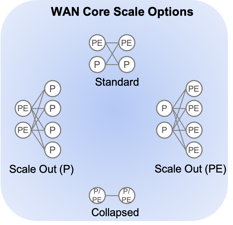
Having more, smaller routers increases the amount of connectivity while reducing the blast radius of a single failure. A single router can fail (or be taken out of service for upgrade) with a much smaller impact on the network. While scale out results in more boxes to manage, automation can be used to reduce complexity and ensure consistency across the network.
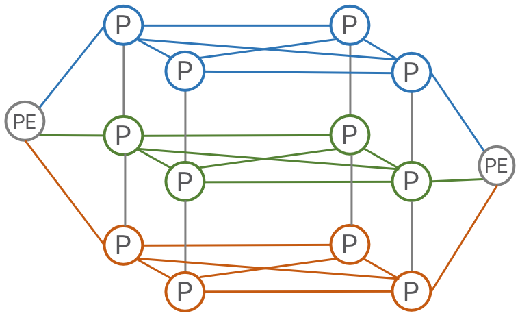
The reference topology for the SD-WAN Core design supports the standard 1+1 deployment, the collapsed P/PE deployment for small deployments, and a simple scale-out.
Multi-Planar Topologies for High Availability
Organizations seeking very highly available networks and/or physical isolation of traffic have long been intrigued with the idea of multi-planar networks. In a multi-planar network, two or more networks are built in parallel, sometimes with diverse hardware and software in each plane to guard against parallel faults. The classic “dual-core” and “unified multi-planar” designs are proven designs with high 9s availability. However, the complexity of traffic steering, convergence time issues and the sheer cost of redundant networks have remained a barrier to widespread deployment.
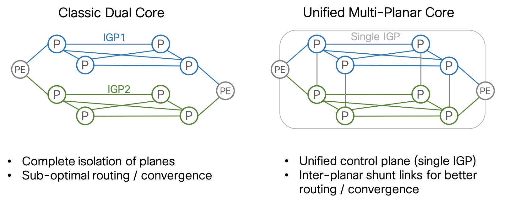
Two recent innovations have brought multi-planar architectures back into the spotlight. First, Segment Routing Flexible Algorithm (“Flex-Algo”) has made it simple to define multiple distinct topologies under the control of a single IGP. Flex-Algo allows the operator to define strict disjoint paths for some traffic while leveraging the ECMP and resiliency of both planes for other traffic, all without complicated affinities or traffic steering configurations.
The second innovation is the high-density NCS 5500 series router which leverages merchant silicon to provide high-density 100 GE while reducing space, power and cost. With a lower cost per port, building two or even three planes is no longer cost-prohibitive.
Platforms

Hardened by years of production deployments inside the most demanding Service Provider networks, the ASR9000 series router is the flagship platform for SD-WAN Core. The ASR9000 is a high-density platform with a modular design capable of delivering up to 3.2 Tbps per slot. The ASR9000 offers industry-leading Segment Routing capabilities, richly featured custom silicon for network analytics, support for advanced features like multicast and Segment-Routing Traffic Matrix (SR-TM), and the highest possible route scale. The ASR9000 series is an excellent choice for multiple roles, from PE (LER) to converged P/PE (LER and LSR) to P (LSR).
A minimal ASR9000-based core can leverage the ASR9901 for 16x1 GE, 24x 1/10 GE, and 2x100 GE in 456 Gbps of nonblocking, full-duplex fabric capacity in 2RUs. Deployments needing more capacity can leverage the ASR9904 (2 RSPs, 2 Line Cards), ASR9906 (2 RSPs, 4 Line Cards), ASR9910 (2 RSPs, 8 Line Cards), ASR9912(2 RSPs, 10 Line Cards), or ASR9922(2 RSPs, 20 Line Cards) for up to 160 Tbps capacity.
When space, power and cost are of primary concern, the Cisco NCS5500 platform can also be deployed in the SD-WAN Core. The NCS5500 series offers large RIB and FIB scale, buffer capacity, and the highest bandwidth scale. The NCS5500 is space and power efficient with 36x100GE in a 1RU fixed form factor or single modular line card. The NCS5500 is a good choice for the P (LSR) router and simple PE (LER) roles. Its low cost-per-port can make multi-planar and/or scale-out topologies possible where they weren’t before.
A minimal NCS5500-based core can provide 36x100GE, 144x10GE, or a mix of non-blocking connections with full resiliency in 4RU. Fixed chassis are ideal for incrementally building a scale-out fabric: the NCS NC55-36X100GE-A-S and NC55A1-24H are efficient high density building blocks which can be rapidly deployed as needed without installing a large footprint of devices day one. Deployments needing more capacity or interface flexibility can utilize the NCS5504 4-slot, NCS5508 8-slot or NCS5516 16-slot modular chassis.
All ASR9000 and NCS5500 routers contain powerful Route Processors to unlock multi-dimensional, model-based programmability and high-speed telemetry.
Control-Plane
 The SD-WAN core design introduces a simplified control-plane built on Segment Routing that supports scale and efficiency in transport.
Segment Routing extensions advertise MPLS Labels for devices (Prefix-SIDs) and links (Adjacency-SIDs) as part of the IGP which enables a simplified forwarding plane, eliminates the need for LDP and RSVP, and increases scale and stability by eliminating the heavy amount of control plane state the router must manage while maintaining an RSVP-TE mesh. With Segment Routing, traffic can be source-routed to a node SID or an anycast SID representing a set of nodes. ECMP behavior is preserved at each point in the network and redundancy is simplified.
Segment Routing was designed to co-exist and interoperate with existing networks. Mapping servers advertise prefix-SIDs on behalf of non-SR nodes and SR and LDP play well together in the data plane.
Because each node in the domain calculates a primary and backup path, Segment Routing automatically provides a Fast ReRoute (FRR) mechanism using Topology Independent Loop Free Alternative (TI-LFA). TI-LFA requires no additional signaling protocol and typically provides convergence times below 50 ms with 100% link and node protection. TI-LFA automatically protects SR, LDP and IP traffic.
More information on Segment Routing technology and its future evolution can be found at http://segment-routing.net
Telemetry
The core design uses the rich telemetry available in IOS-XR to enable an unprecedented level of insight into network and device behavior. Model-Driven Telemetry and NETCONF combined with standard and native YANG models enables rapid statistics collection. Telemetry configuration and applicable sensor paths have been identified to assist network operators in knowing what to monitor and how to monitor it. Through streaming data mechanisms such as Model-Driven Telemetry, operators can extract data useful for operations, capacity planning, security, and many other use cases.
The ASR9000 series router also supports Segment-Routing Traffic Matrix (SR-TM) for advanced, bandwidth-based traffic-engineering.
The core also fully supports traditional collections methods such as SNMP and NETCONF using YANG models to integrate with legacy systems.
Automation
In this design, NETCONF and YANG (using OpenConfig and native IOS-XR data models) form the basis of configuration automation. Cisco has developed example Network Service Orchestrator (NSO) services to help automate common Segment Routing migration tasks using NETCONF NEDs.
Use Cases
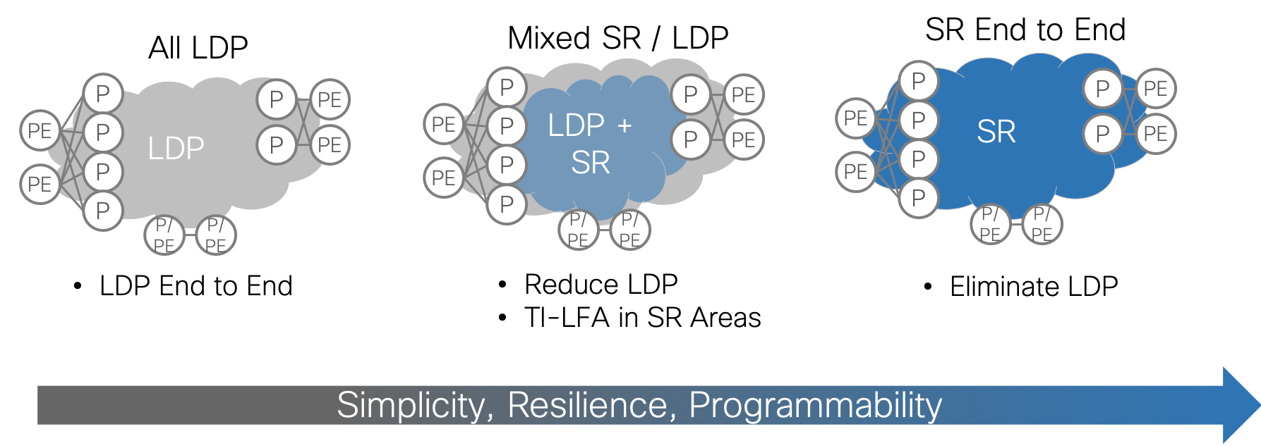
Simplification: LDP to SR Migration
Many customers with existing MPLS backbones run LDP in the core today. To simplify and scale, one of the most important steps is to migrate from LDP to Segment Routing (SR). The benefits of SR are clear: protocol simplification, simplified resiliency, and multi-domain programmability. What is less clear is how to accomplish the migration. Greenfield networks are rare and pockets of LDP will continue to exist in most networks for a long time to come. The SD-WAN Core design approaches simplification through SR migration in a series of steps that are intended to maintain existing functionality while gradually enabling SR and transitioning traffic to SR LSPs. Each migration step has an example NSO service profile associated with it to ensure a consistent, best-practice implementation.
While end-to-end SR is the goal, it may not always be possible at a given point in time. Customers may be looking to refresh the P routers and not the PE routers. Legacy PE routers may not support SR even if new PEs do. Therefore, it is important to find value at each step of the migration and maintain support for non-SR PEs through the process.
Starting Point
The migration use case assumes that the existing WAN Core is already configured as a functional MPLS network with the following characteristics:
- Single instance of ISIS as the IGP
- LDP for label distribution
- BGP-free core
- Working L2/L3 VPN services from PE to PE using BGP
The goal of the migration is to preserve existing services while migrating the core in an incremental, validated, step-by-step fashion. 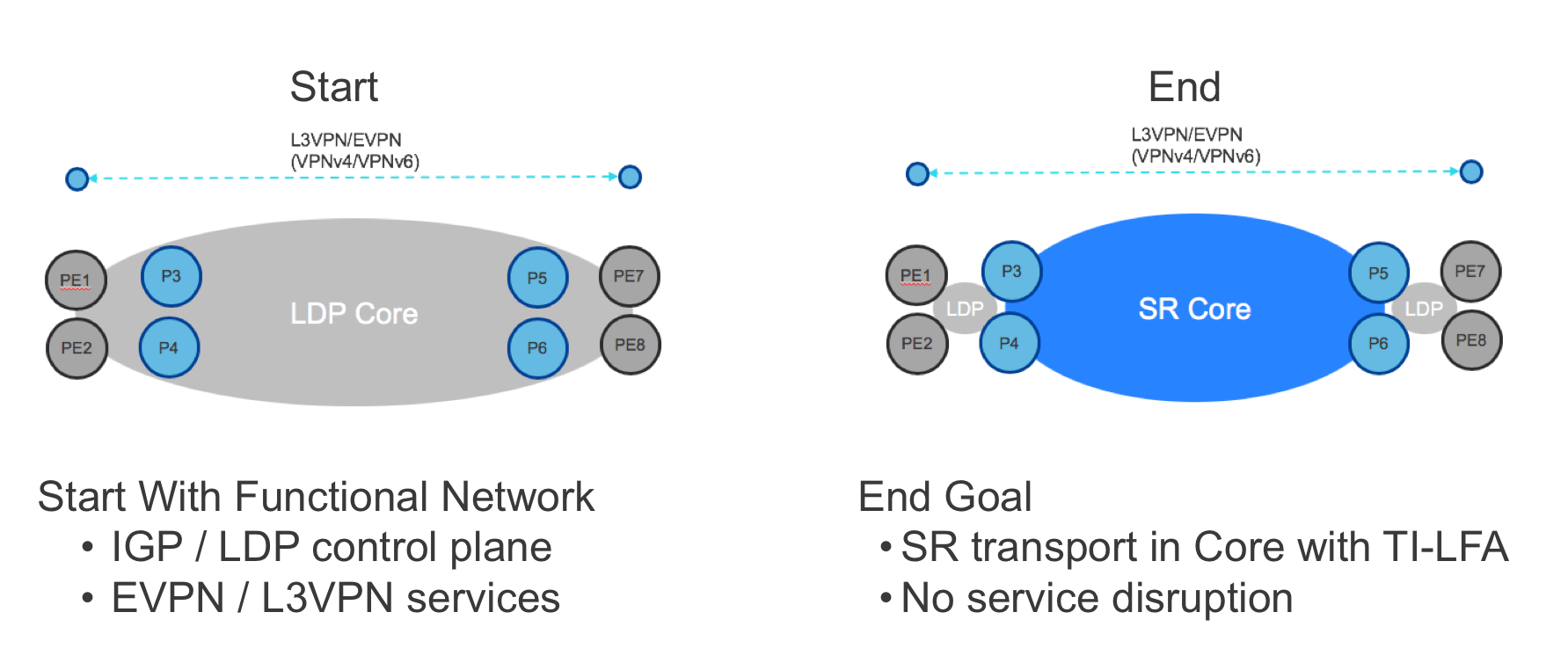
Step 1: Enable SR
In the first step of migration, SR is enabled on the P routers using CLI or (preferably) NETCONF/YANG. The latter can be orchestrated using the example NSO sr service, ensuring that:
- Every router uses the same ISIS instance, loopback interface and global block of labels.
- Every router is assigned a unique prefix-SID from the global block of labels.
- The SR service can be rolled out across multiple devices in a transactional fashion and seamlessly rolled back if needed.
Deploying SR by itself in this way will not impact the forwarding plane in any way: the P routers will continue to use LDP labels to forward traffic until 1) the PE routers use SR or 2) LDP is disabled in the core. Nevertheless, it is possible to deeply validate the operation of SR even while still using LDP forwarding. The following validations can be performed via CLI or (preferably) a model-based query method such as NETCONF/YANG, YDK, or NSO’s live-status capability:
- Each router successfully assigns the desired block from the label database.
- The IGP is advertising SR labels for every SR-enabled router’s loopback.
- Each router is programming the SR labels in the RIB and FIB.
- Traffic is forwarded using LDP labels.
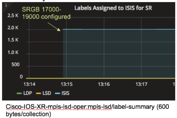
YANG-modeled operational data can also be streamed using model-driven telemetry. In this example, model driven telemetry is streaming Cisco-IOS-XR-mpls-lsd-oper:mpls-lsd/label-summary data, making it easy to see that the number of labels assigned to ISIS jumps to 2000 when the SR global block of labels is configured.
Step 2: Enable Mapping Servers
In this step, mapping servers are configured to provide SR labels for LDP-only endpoints, specifically the loopback addresses of non-SR PEs. Mapping servers can be configured anywhere in the network. At least two mapping servers should be configured for redundancy.
This step can be achieved through CLI or NETCONF/YANG. To automate the process, use the example NSO sr-ms service which leverages the same infrastructure as the “sr” service to simplify and ensure consistency in the configuration process.
At the end of this step, the P routers will have SR labels for all P and PE routers. However, the VPN services will still use the LDP LSPs from end-to-end since the non-SR PE routers still initiate the service with an LDP label.
To validate the Mapping Server configuration, check that the non-SR endpoint addresses are represented by labels in the IGP, RIB and FIB as in Step 1.
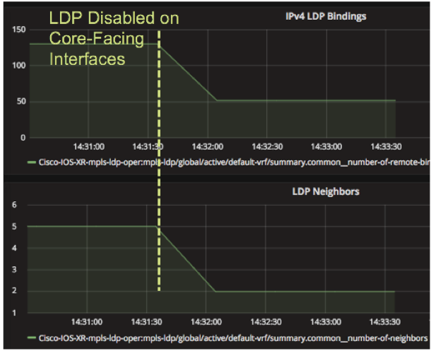
Step 3: Protocol Elimination
 Once the P routers are fully configured for SR, LDP can optionally be disabled on a link-by-link basis for every link pair that has SR enabled on each end. When this step is accomplished, the P routers will use the SR label for the path across the core. The benefit of this step is fewer protocols to maintain and troubleshoot in the core. There should be no impact to the VPN services when the transition is made.
The example disable-ldp service can be used in NSO to orchestrate this step on a link-by-link basis. Telemetry can be used to track the impact of disabling LDP on core-facing interfaces using the Cisco-IOS-XR-mpls-ldp-oper:mpls-ldp/global/active/default-vrf/summary path.
Some customers may choose not to disable LDP in the core until all PE routers have been migrated to SR as well, creating an end-to-end SR deployment. In that case, LDP provides the primary forwarding path. SR can provide TI-LFA until the rest of the network is ready to switch to SR.
LDP to SR End-to-End Migration
In the case where the PE devices are SR-capable, the previous use cases can be extended to run SR end-to-end. This can be done incrementally on a PE by PE basis until all PEs are migrated. The benefits of this additional step include end-to-end TI-LFA and further reduction in LDP maintenance.
The goal of this use case is the same as before: enable full or partial migration of the PE devices without service disruption. 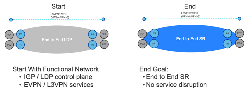
Step 1: Enable SR on the PEs
Enabling SR on the PEs will happen in two stages. First, SR will be enabled but not preferred. This means that the PEs will learn SR labels for all the endpoints in the network but still initiate the VPN services using LDP labels. This step can be accomplished using the same NSO sr service as the P routers in the previous use case and validation follows the same steps for the PE routers.
Step 2: Enable SR on the PEs
Finally, the PEs will be configured to prefer sr one by one, slowly transitioning the traffic to end-to-end SR. The example NSO sr service includes an option for sr-prefer in the “sr” service. LDP can then be disabled on the PEs as well.
Availability: TI-LFA
Classic, IP-based Loop-Free Alternative (LFA) provides simple, automatic, sub-50 milisecond per-prefix fast reroute. The IGP pre-computes the backup path and installs it in the data-plane so that they can be quickly enabled on local failure. However, classic LFA is topology-dependent, does not provide full coverage and can result in sub-optimal backup paths.
With Segment Routing, it is possible to achieve Topology-Independent LFA (TI-LFA) which is not dependent on topology. TI-LFA provides 100% coverage for link and node protection with the same sub-50 milisecond convergence time. TI-LFA uses the optimal, post-convergence path as the backup path which prevents transient congestion associated with sub-optimal backup paths. Since the IGP automatically computes the backup paths, TI-LFA is simple to configure and operate.
Like all Segment Routing features, TI-LFA is designed for incremental deployments and migration scenarios. It can (and should) be deployed when Segment Routing is enabled in the network. Once enabled, TI-LFA will protect all traffic (SR, LDP and IP) regardless of whether SR is the primary forwarding mechanism.
The simple, fast and complete protection of TI-LFA has application in many industries with high availability requirements.
TI-LFA for Utilities: Utilities and energy providers have mission-critical control data that requires extremely high availability. TI-LFA can help reduce downtime and maintain continuous access to critical applications.
TI-LFA for Financials: Financial institutions carry enormous loads of bank transactions. The transactions are almost all quite tiny and even a few seconds of network outage can mean millions of dropped transactions. Recovery from even very short outages can be difficult due to the sheer number of retransmissions. TI-LFA can reduce the number of dropped transactions and help prevent massive backups on retransmission.
TI-LFA for Healthcare: Hospitals and healthcare providers need continuous uptime and 24/7 operations. TI-LFA can help high-priority clinical systems (like life-support and telemedicine systems) that need uninterrupted network access.
Enabling TI-LFA
 Configuring TI-LFA is simple. The example NSO ti-lfa service simplifies the configuration process even further by automatically enabling TI-LFA under every non-loopback interface in the given ISIS instance.
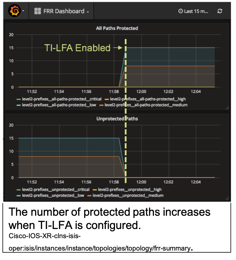
As soon as it is enabled, TI-LFA protects IP, LDP and SR traffic. This means that all traffic in the Core now has the benefit of sub-50 millisecond convergence times without complicated RSVP-TE tunnels. Network availability is improved even before the primary forwarding plane is switched to SR.
The operation of TI-LFA should be validated to ensure that all paths are protected. YANG models can be used to retrieve or stream the relevant operational data.
Availability with Multi-Planar Designs
Where TI-LFA is a control plane feature for HA, multi-planar networks build availability into the topology by separating the network into independent, parallel planes. Faults in one plane will not affect traffic in another plane.
Segment Routing Flex-Algo makes it easier to carve the network into multiple planes while maintaining the simplicity of managing a single IGP across all planes. Flex-Algo leverages the wider SR Traffic Engineering architecture and the computational power of the IGP to compute paths across custom topologies.
In the following picture, the green nodes have been configured with Algo 128 and the red nodes with Algo 129 (in addition to the default Algo 0). The white nodes participate in all Algos.
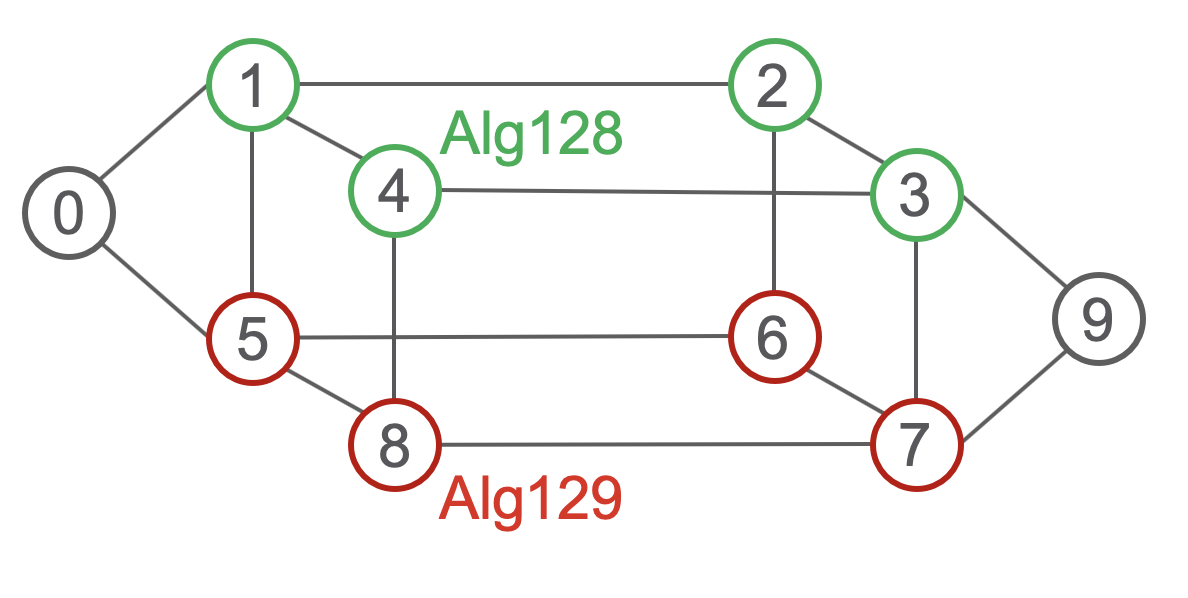
Traffic steered into Algo 128 will never traverse the red nodes. Traffic steered into Algo 129 will never traverse the green nodes. Traffic that is not steered into a particular Algo will go into the default Algo 0 which will use ECMP paths across green and red nodes.
Failures are isolated to an Algo. Because each Algo defines its own topology, failures in one Algo will not cause recalculation in nodes that that don’t participate in that Algo. All the usual features of Segment Routing work the same: traffic steering can be automated with On-Demand Next-Hop (ODN), which uses BGP route colors to steer traffic into the chosen Flex-Algo. TI-LFA operates per-Algo as well.
There are many applications of multi-planar architectures:
Data Center Backup: Data center backups usually involve large amounts of data but relatively few constraints on latency. If one of your Flex-Algo planes is defined as a “Best Effort” plane, you can steer backup traffic onto this plane and keep it isolated from other planes that might carry traffic with real-time constraints.
Prioritized Market/Transaction Data: Banks and financial institutions might want to use Flex-Algo to create a separate topology for high priority trafffic like market data or financial transactions. This data will be isolated from best-effort traffic in its own plane.
Maintenance Mode: Having more than one plane enables you to take one plane out of service for maintenance without network downtime. For example, if you wanted to take the routers in the red plane out of service for upgrade, you could modify the traffic engineering policy at the head end to temporarily steer all traffic into the green plane. Once the red plane is back in service, traffic could be restored to the original planes. This can also be achieved without Flex-Algo by costing up the links on the plane that needs maintenance to drain traffic away from it.
- Dual Failure / Triple Plane: A dual-plane architecture insures availability when one plane fails or is out of service. But what if there is a second failure when one plane is down? It is possible to have an outage that takes hours or even days to detect and fix. During that period, there is no HA. One solution to this is to build a third parallel plane. With three planes, the network can sustain double faults and still operate.
Traffic Engineering
Segment Routing offers an abundance of other Traffic Engineering (TE) features that can be used with or without Flex-Algo. SR-TE calculate low-latency paths, paths that include or exclude certain affinities or SRLGs, and paths that use an arbitrary metric.
Low Latency Path for Real-time Traffic
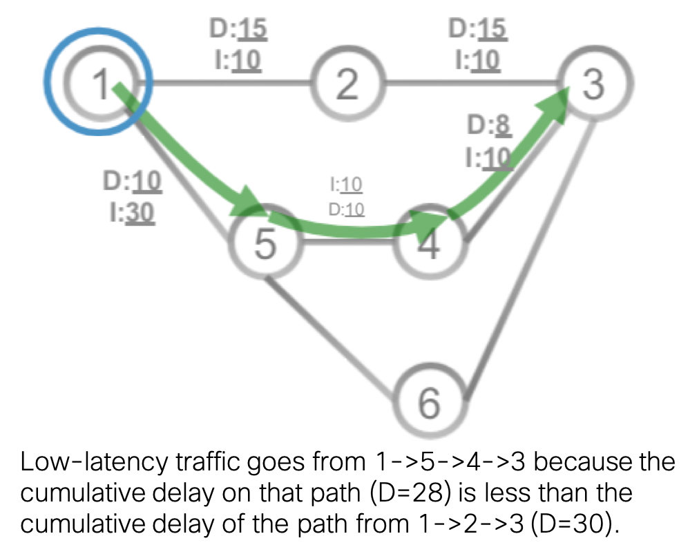 Instead of (or in addition) to directing traffic onto a particular plane, you might want to direct certain traffic on the lowest latency path. This might be real-time traffic like voice or video or latency-sensitive applications (like market data or transactions). Latency can either be statically configured on a link or dynamically collected using Segment Routing Performance Monitoring (SR-PM). SR-PM uses a query and response mechanism (RFC 6374) to measure one-way and two-way link delay which is then advertised in the IGP. SR-TE uses the advertised minimum delay to calculate the lowest latency path. As usual, ODN can automatically steer traffic into the low-latency path.
Link Affinity with Encrypted Path
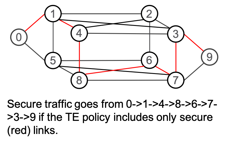 SR-TE can include or exclude links based on their configured affinity. One use case for this is a network that has some links that are secured by MACSec and some that are not. Business policy may dictate that some traffic must only traverse encrypted links. By assigning a “secure” affinity to links with MACSec enabled and building an SR-TE policy that only includes “secure” links, you can guarantee that traffic matching that policy will always be encrypted.
Bandwidth Optimization
Even in well-designed networks, there will be periods when certain links are temporarily congested. QoS mechanisms can be used to ensure that low priority traffic is dropped first, but it would be even better if the network could detect over-utilized links and steer lower-priority traffic off the shortest path, freeing up bandwidth for high priority traffic on the shortest path while ensuring that lower-priority traffic gets to its destination. This is the goal of the bandwidth optimization use case.
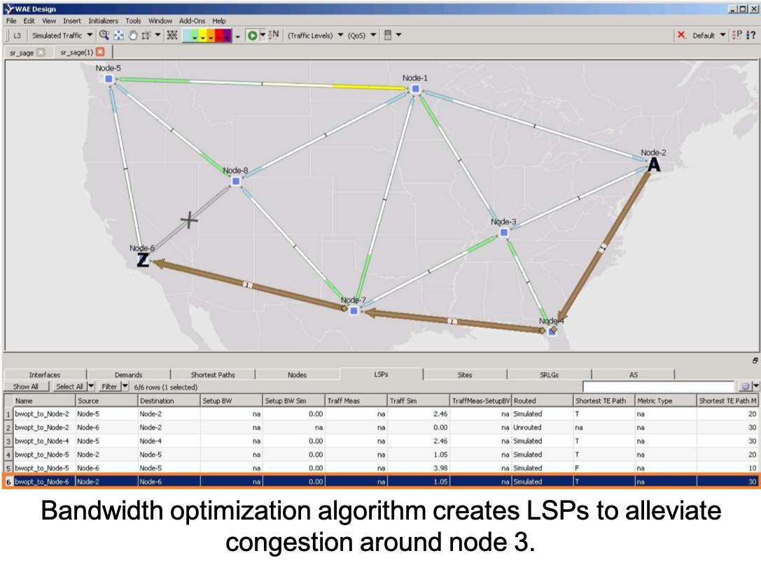
Since bandwidth utilization is not carried in the IGP, SR-TE cannot compute the path on its own. Therefore, the routers in the network must send link utilization data to a bandwidth optimization application. This data is most efficiently streamed used Segment Routing Traffic Matrix (SR-TM). When the platform does not support SR-TM, the bandwidth application can use SNMP data to calculate a demand matrix (a much slower process than SR-TM). In any event, when the bandwidth application detects an over-utilized link, it can deploy an SR-TE policy to redirect traffic to different paths. When link utilization falls back to acceptable levels, the SR-TE policy can be removed. This is an example of reactive traffic engineering.
Egress Peering Engineering
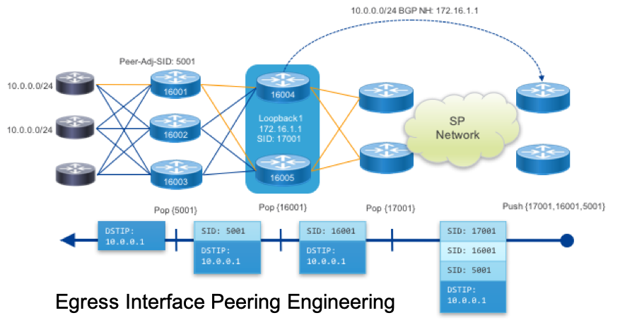 SD-WAN Core networks can use Peering to directly connect to content and service providers on the Internet. You can use SR-TE policies to engineer how traffic crosses your network to reach egress peers (hence the name Egress Peering Engineering). SR-TE makes it possible to direct traffic from deep in your network to specific egress nodes, egress interfaces, egress peers or set of peers. For example, you may want to create a low-latency path to a particular egress peer for a latency-sensitive SaaS application. Or you may want best-effort traffic to egress through a link to a less expensive peering arrangement.
Through the use of Anycast SIDs, traffic can be load balanced between several peer nodes as well, simplifying the process of balancing egress traffic.
SD-Wan Integration at Access
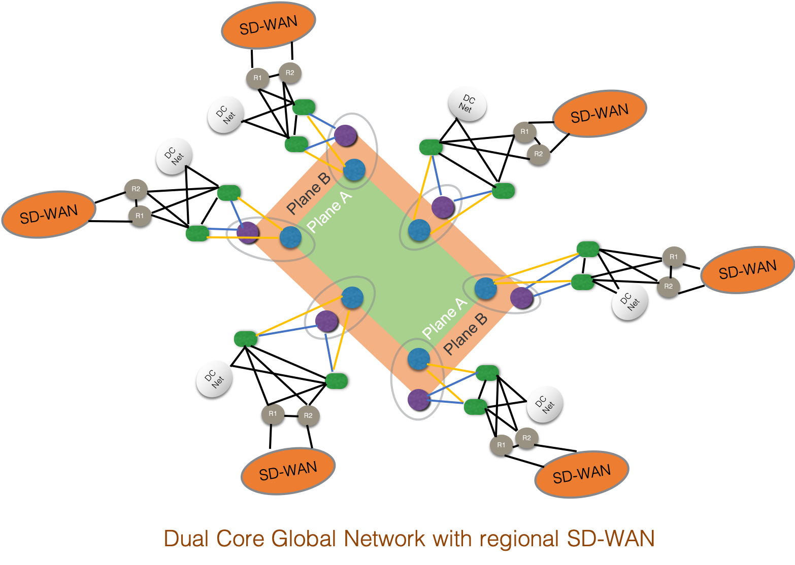 SD-WAN overlays provide security and segmentation over various underlays, including the Internet, 4G networks and private, service-provider-managed MPLS VPNs. Given that the SD-WAN Core offers security, scale, segmentation and SLAs as part of the underlay, you might be tempted to think that SD-WAN overlay has no place in an SD-WAN Core. This is not the case.
In large, global networks, SD-WAN overlays work well to bring traffic from remote branches and small sites to a regional hub (e.g. the Colos discussed earlier), at which point the traffic jumps onto the WAN Core network. Using SD-WAN allows the organization to leverage the local ISP for regional transport (which is typically very cost efficient) and competitive EPL services between Colos for global transport. This kind of design has been proven to scale to well over 10,000 sites around the world.
Conclusion
The Secure SD-WAN Core based on Segment Routing is a proven design with production deployments in Enterprise and Public Sector networks. In addition to being simple, secure, and available, the design can be customized to fit diverse business requirements: connecting to Cloud, leveraging cost-efficient transport and Colos, securing and segmenting traffic, achieving the highest possible levels of network availability. Backed by the power of Segment Routing and the industry-leading IOS XR operating system, Secure SD-WAN Core is the future of large network design for global Enterprises and Public Sector organizations.
For More Information
NSO
NSO Example Services for Segment Routing
Simpler Segment Routing with NSO – The Inside Story
Leave a Comment