
Implementing Layer3 VPN over SRv6 Transport on NCS 5500/500
| Paban Sarma, Technical Marketing Engineer ([email protected]) |
| Tejas Lad, Technical Marketing Engineer ([email protected]) |
Overview
In Previous Article, we discussed how to set up segment routing v6 (SRv6) transport on the NCS 500 and NCS 5500 platforms. In this article, we will explore setting up Layer3 vpn services over SRv6 transport.
Topology
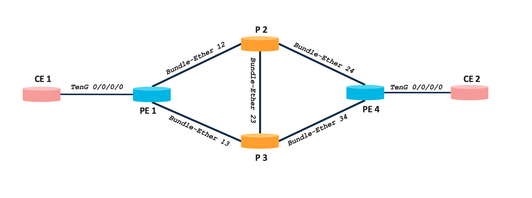
The topology used is a simple four node network comprising of Cisco NCS 540 and NCS 5500 series platforms. There are two CE nodes connected to PE1 and PE4 respectively to simulate customer networks. Details of each node along with Loopback IPs are mentioned in the below table.
| Nodes | Device Type | Software Version | Loopback0 |
|---|---|---|---|
| PE1 | NCS 540 | IOS XR 7.5.2 | fcbb:bb00:1::1/128 |
| P2 | NCS 5500 | IOS XR 7.5.2 | fcbb:bb00:2::1/128 |
| P3 | NCS 5500 | IOS XR 7.5.2 | fcbb:bb00:3::1/128 |
| PE4 | NCS 5500 | IOS XR 7.5.2 | fcbb:bb00:4::1/128 |
The loopback0 IPs are chosen as per the SRv6 addressing best practice (check out segment-routing.net for more details).
In this tutorial, we will establish a L3VPN (VPNv4) connecting two subnets across CE1 and CE2.
Configuration & Verification for VPNv4
Configuring BGP Control Plane
At first, we will set up the BGP control plane with VPNv4 address family between PE1 and PE4. We are directly peering between PE1 and PE4 in this example, however in a real network there can be route reflectors used for BGP to improve simplicity and scalability.
BGP configuration on PE1
router bgp 100
 bgp router-id 1.1.1.1
 address-family vpnv4 unicast
 !
 neighbor fcbb:bb00:4::1
  remote-as 100
  update-source Loopback0
  address-family vpnv4 unicast
  !
 !
!
BGP configuration on PE4
router bgp 100
 bgp router-id 4.4.4.4
 address-family vpnv4 unicast
 !
 neighbor fcbb:bb00:1::1
  remote-as 100
  update-source Loopback0
  address-family vpnv4 unicast
  !
 !
!
We can verify the BGP neighbourship with VPNv4 AFI using show bgp vpnv4 unicast summary
RP/0/RP0/CPU0:LABSP-3393-PE1#show  bgp  vpnv4 unicast summary
BGP router identifier 1.1.1.1, local AS number 100
BGP generic scan interval 60 secs
Non-stop routing is enabled
BGP table state: Active
Table ID: 0x0
BGP main routing table version 23
BGP NSR Initial initsync version 2 (Reached)
BGP NSR/ISSU Sync-Group versions 0/0
BGP scan interval 60 secs

BGP is operating in STANDALONE mode.


Process       RcvTblVer   bRIB/RIB   LabelVer  ImportVer  SendTblVer  StandbyVer
Speaker              23         23         23         23          23           0

Neighbor        Spk    AS MsgRcvd MsgSent   TblVer  InQ OutQ  Up/Down  St/PfxRcd
fcbb:bb00:4::1    0   100      10      12       23    0    0 00:00:26          0
Configuring VRF and PE-CE links
The next step is to confgure the virtual forwarding instances (VRFs) on each PE. We are using vrf 1 on both PE1 and PE4. The following needs to be configured on both the nodes. Note that we are using the same route-targets import/export on both ends.
vrf 1
 address-family ipv4 unicast
  import route-target
   100:1
  !
  export route-target
   100:1
  !
 !
!
For simplicty, we will connect subnet 192.168.1.0/24 present in CE1 to 192.168.2.0/24 present in CE2. We are using a PE-CE subinterface (with VLAN 1) under VRF 1 on PE1 and PE4. On both of the CE nodes we are using static routing to reach gateway PE. For a scaled network, there can be eBGP or other routing protocols for exchange of route information between PE and CE which is out of scope for this tutorial. The respective configurations on the PE/CE nodes are listed below:
PE1
interface TenGigE0/0/0/0.1
 vrf 1
 ipv4 address 192.168.1.1 255.255.255.0
 encapsulation dot1q 1
PE4
interface TenGigE0/0/0/0.1
 vrf 1
 ipv4 address 192.168.2.1 255.255.255.0
 encapsulation dot1q 1
CE1
interface TenGigE0/0/0/0.1
 ipv4 address 192.168.1.10 255.255.255.0
 encapsulation dot1q 1
!
router static
 address-family ipv4 unicast
  192.168.2.0/24 192.168.1.1
 !
!
CE2
interface TenGigE0/0/0/0.1
 ipv4 address 192.168.2.10 255.255.255.0
 encapsulation dot1q 1
!
router static
 address-family ipv4 unicast
  192.168.1.0/24 192.168.2.1
 !
!
Configuring VRF under BGP
Now to establish the L3VPN, the final step is to advertise the VRF routes via BGP. This is established by configuring the VRF under BGP on each PE. For simplicity we are using auto rd under the VRF and redistributing the connected routes. For SRv6 we will specify the locator to be used and the label mode as per VRF.
The following configurations needs to be added on both PE1 and PE4.
router bgp 100
 vrf 1
  rd auto
  address-family ipv4 unicast
   segment-routing srv6
    locator POD0
    alloc mode per-vrf
   !
   redistribute connected
Verification of VPNv4
The control plane for the layer3 VPN established can be verified using different CLI commands related to SRv6 SIDs and BGP. We can see the respective uSIDs (uDT4) on each PE for the VRF using show segment routing srv6 sid
RP/0/RP0/CPU0:PE1#show segment-routing  srv6 locator POD0 sid

SID                         Behavior          Context                           Owner               State  RW
--------------------------  ----------------  ------------------------------    ------------------  -----  --
fcbb:bb00:1::               uN (PSP/USD)      'default':1                       sidmgr              InUse  Y
fcbb:bb00:1:e004::          uDT4              '1'                               bgp-100             InUse  Y

RP/0/RP0/CPU0:PE4#show segment-routing  srv6 locator POD0 sid

SID                         Behavior          Context                           Owner               State  RW
--------------------------  ----------------  ------------------------------    ------------------  -----  --
fcbb:bb00:4::               uN (PSP/USD)      'default':4                       sidmgr              InUse  Y
fcbb:bb00:4:e000::          uDT4              '1'                               bgp-100             InUse  Y
The Prefix received from BGP can also be verified using some of the commands/outputs listed below:
RP/0/RP0/CPU0:LABSP-3393-PE1#show  bgp  vpnv4 unicast summary

BGP is operating in STANDALONE mode.


Process       RcvTblVer   bRIB/RIB   LabelVer  ImportVer  SendTblVer  StandbyVer
Speaker              23         23         23         23          23           0

Neighbor        Spk    AS MsgRcvd MsgSent   TblVer  InQ OutQ  Up/Down  St/PfxRcd
fcbb:bb00:4::1    0   100      12      14       23    0    0 00:02:08          1

RP/0/RP0/CPU0:PE1#show  bgp  vpnv4 unicast received-sids


Status codes: s suppressed, d damped, h history, * valid, > best
              i - internal, r RIB-failure, S stale, N Nexthop-discard
Origin codes: i - IGP, e - EGP, ? - incomplete
   Network            Next Hop                            Received Sid
Route Distinguisher: 1.1.1.1:0 (default for vrf 1)
*> 192.168.1.0/24     0.0.0.0                             NO SRv6 Sid
*>i192.168.2.0/24     fcbb:bb00:4::1                      fcbb:bb00:4:e000::
Route Distinguisher: 4.4.4.4:0
*>i192.168.2.0/24     fcbb:bb00:4::1                      fcbb:bb00:4:e000::

Processed 3 prefixes, 3 paths

RP/0/RP0/CPU0:PE#show  route vrf 1


Gateway of last resort is not set

C    192.168.1.0/24 is directly connected, 2w6d, TenGigE0/0/0/0.1
L    192.168.1.1/32 is directly connected, 2w6d, TenGigE0/0/0/0.1
B    192.168.2.0/24 [200/0] via fcbb:bb00:4::1 (nexthop in vrf default), 00:03:46
The above outputs are taken from PE1 for reference. We can also verify the equivalent outputs on the other end (i.e PE4). Now if we check the CEF entry in PE4, we can see that it points to the respective uDT4 SID on PE1.
RP/0/RP0/CPU0:LABSP-3393-PE4#show cef vrf 1 192.168.1.0/24
192.168.1.0/24, version 11, SRv6 Headend, internal 0x5000001 0x30 (ptr 0x8afe0198) [1], 0x0 (0x0), 0x0 (0x8bf261e8)
 Updated Sep 22 05:09:52.385
 Prefix Len 24, traffic index 0, precedence n/a, priority 3
  gateway array (0x8c49f0a8) reference count 1, flags 0x2010, source rib (7), 0 backups
                [1 type 3 flags 0x48441 (0x8a097128) ext 0x0 (0x0)]
  LW-LDI[type=0, refc=0, ptr=0x0, sh-ldi=0x0]
  gateway array update type-time 1 Sep 22 05:09:52.385
 LDI Update time Sep 22 05:09:52.407

  Level 1 - Load distribution: 0
  [0] via fcbb:bb00:1::/128, recursive

   via fcbb:bb00:1::/128, 3 dependencies, recursive [flags 0x6000]
    path-idx 0 NHID 0x0 [0x8b091778 0x0]
    next hop VRF - 'default', table - 0xe0800000
    next hop fcbb:bb00:1::/128 via fcbb:bb00:1::/48
    SRv6 H.Encaps.Red SID-list {fcbb:bb00:1:e004::}

    Load distribution: 0 1 (refcount 1)

    Hash  OK  Interface                 Address
    0     Y   Bundle-Ether24            fe80::28a:96ff:fe2d:18db
    1     Y   Bundle-Ether34            fe80::28a:96ff:fe2c:58db
We can also verify that the destination SID is a combination of the remote node SID (uN) and the received label using the below command:
RP/0/RP0/CPU0:LABSP-3393-PE4#show  bgp vrf 1 192.168.1.0/24
BGP routing table entry for 192.168.1.0/24, Route Distinguisher: 4.4.4.4:0
Versions:
  Process           bRIB/RIB  SendTblVer
  Speaker                  21           21
Last Modified: Sep 22 05:09:51.939 for 00:04:52
Paths: (1 available, best #1)
  Not advertised to any peer
  Path #1: Received by speaker 0
  Not advertised to any peer
  Local
    fcbb:bb00:1::1 (metric 30) from fcbb:bb00:1::1 (1.1.1.1)
      Received Label 0xe0040
      Origin incomplete, metric 0, localpref 100, valid, internal, best, group-best, import-candidate, imported
      Received Path ID 0, Local Path ID 1, version 21
      Extended community: RT:100:1
      PSID-Type:L3, SubTLV Count:1
       SubTLV:
        T:1(Sid information), Sid:fcbb:bb00:1::, Behavior:63, SS-TLV Count:1
         SubSubTLV:
          T:1(Sid structure):
      Source AFI: VPNv4 Unicast, Source VRF: default, Source Route Distinguisher: 1.1.1.1:0
Finally, the data plane can be verified by simply pinging CE2 from CE1
RP/0/RP0/CPU0:LABSP-3393-CE1#ping  192.168.2.10 repeat 10
Thu Sep  1 09:14:37.319 UTC
Type escape sequence to abort.
Sending 10, 100-byte ICMP Echos to 192.168.2.10, timeout is 2 seconds:
!!!!!!!!!!
Success rate is 100 percent (10/10), round-trip min/avg/max = 1/5/21 ms
Summary
This concludes the tutorial on provisioning Layer3 VPN services over SRv6 transport on NCS 500 and 5500 platforms. We covered sample example of VPNv4 service. Similarly VPNv6 can also be configured (uDT6). Stay tuned for upcoming tutorial covering layer2 services over SRv6 transport.
Leave a Comment