
BGP-EVPN Configuration on NCS 5500 part-2
Topic: BGP-EVPN based MC-LAG for Multi-Homing of devices
This post will cover BGP-EVPN based MC-LAG for Multi-Homing of devices. Multi-homing is achieved by EVPN Ethernet Segment feature; it offers redundant connectivity and utilizes all the links for active/active per-flow load balancing. For EVPN Multi-Homing tutorial, we will leverage EVPN control-plane and ISIS Segment Routing based forwarding that we configured in the previous post.
EVPN Ethernet segment is a set of Ethernet links that connects a multi-homed device. If a multi-homed device or network is connected to two or more PEs through a set of Ethernet links, then that set of links is referred to as an Ethernet segment. Each device connected in the network is identified by a unique non-zero identifier called Ethernet-Segment Identifier (ESI).
On NCS 5500 platform, following modes of operation are supported.
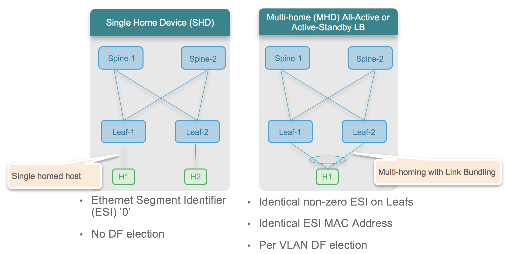
- Single-Homing — A device is single-homed when its connected to only one Leaf or PE. There is no redundancy in this mode of operation and it does not need Ethernet Segment to be configured.
- Active-Active Multi-Homing — In active-active multi-homing mode, a device is multi-homed to multiple Leafs/PEs and both the links actively forward the traffic on that Ethernet Segment. This mode of operation is bandwidth efficient and provides per-flow active/active forwarding.
- Single-Active Multi-Homing — In active-standby multi-homing mode, a device is multi-homed to multiple Leaf/PEs and only one link is in active state to forward the traffic on that Ethernet Segment. In case of failure of the active link the standby link takes over and starts forwarding for that Ethernet Segment.
BGP-EVPN based multi-homing benefits over traditional MC-LAG
There are traditional ways to implement MC-LAG and then there is BGP EVPN based multi-homing. Following table lists some of the benefits of BGP-EVPN based multi-homing over traditional MC-LAG.
| Traditional MC-LAG | EVPN Multi-Homing with Ethernet-Segment |
| Dedicated inter-chassis links required. This needs to be sized according to access bandwidth | Dedicated inter-chassis link not mandatory, but can be used optionally if needed |
| State sync between nodes is via proprietary protocol/mechanism | State synchronization between nodes is via BGP |
| Prefix independent convergence on attachment circuit (AC) failure not possible | BGP-EVPN provides prefix independent convergence on attachment circuit failure |
| Only 2-way redundancy is practical (due to requirement of inter-chassis link) | N-way redundancy is possible. |
Note: NCS 5500 platform supports only BGP-EVPN based multi-homing with 2-way redundancy.
Reference Topology

Task 1: Configure LACP bundle on Host-1
As per the reference topology Host-1 is dual-homed to Leaf-1 and Leaf-2. ASR9K is acting as the host with IP address 10.0.0.10/24. Host-1 is configured with LACP bundle containing the interfaces connected to the Leaf-1 and Leaf-2. Following is the configuration of LAG on Host-1. The LAG on Host-1 will come up after we configure the MC-LAG using EVPN Ether-Segment on the Leaf-1 and Leaf-2.
In this tutorial we are using ASR9K router as the host but we can use any server or other CE device dual-homed connected to the Leaf/PE via BGP-EVPN.
    Host-1

    interface Bundle-Ether 1
     description "Bundle to Leaf-1/2"
     ipv4 address 10.0.0.10 255.255.255.0
    !
    interface TenGigE0/0/2/0
     description "Link to Leaf-1 ten0/0/0/47"
     bundle id 1 mode active
     load-interval 30
    !
    interface TenGigE0/0/2/1
     description "Link to Leaf-2 ten0/0/0/47"
     bundle id 1 mode active
     load-interval 30
    !
Task 2: Configure EVPN based multi-homing for Host-1
Configure Leaf-1 and Leaf-2 to provision all active multi-homing to host-1. The set of links from Host-1 to the Leafs will be configured as an Ethernet Segment on the Leafs. For each Ethernet-Segment, identical ESI along with identical LACP System MAC address should be configured on the Leaf pair. Every Ethernet-Segment has to be configured with its own uniqure LACP System MAC.
NCS 5500 platform supports static LAG as well as LACP, however in this guide we are using LACP for link aggregation.

Configure the bundle on the Leaf-1 and Leaf-2. Use the same config for both the Leafs.
    interface TenGigE0/0/0/47
     description "Link to Host-1"
     bundle id 1 mode active
     load-interval 30
    !
    interface Bundle-Ether 1
     description "Bundle to Host-1"
     lacp system mac 1101.1111.1111
     load-interval 30
    !
Configure Ethernet Segment id (ESI) for the bundle interface to enable multi-homing of the host. Use the identical configuration on both the Leafs. Each device connected in the network should be identified by a unique non-zero Ethernet-Segment Identifier (ESI). We can configure Single-Active load-balancing by CLI command “load-balancing-mode single-active” under “ethernet-segment”. By default the load-balancing mode for ethernet-segment is active/active.
EVPN All Active Multi-Homing Config: (Used in this tutorial)
    evpn
     interface Bundle-Ether 1
      ethernet-segment
       identifier type 0 11.11.11.11.11.11.11.11.11
       bgp route-target 1111.1111.1111>
      !
     !
EVPN Single-Active Multi-Homing Config: (For reference only)
    evpn
         interface Bundle-Ether 1
          ethernet-segment
           identifier type 0 11.11.11.11.11.11.11.11.11
           load-balancing-mode single-active
           bgp route-target 1111.1111.1111
          !
         !
Use “show bundle bundle-ether 1” CLI command to verify the state of the bundle interface on Leafs and Host-1.
    Leaf-1

    RP/0/RP0/CPU0:Leaf-1#show bundle bundle-ether 1

    Bundle-Ether1
      Status:                                    Up
      Local links <active/standby/configured>:   1 / 0 / 1
      Local bandwidth <effective/available>:     10000000 (10000000) kbps
      MAC address (source):                      00bc.601c.d0da (Chassis pool)
      Inter-chassis link:                        No
      Minimum active links / bandwidth:          1 / 1 kbps
      Maximum active links:                      64
      Wait while timer:                          2000 ms
      Load balancing:
        Link order signaling:                    Not configured
        Hash type:                               Default
        Locality threshold:                      None
      LACP:                                      Operational
        Flap suppression timer:                  Off
        Cisco extensions:                        Disabled
        Non-revertive:                           Disabled
      mLACP:                                     Not configured
      IPv4 BFD:                                  Not configured
      IPv6 BFD:                                  Not configured

      Port                  Device           State        Port ID         B/W, kbps
      --------------------  ---------------  -----------  --------------  ----------
      Te0/0/0/47            Local            Active       0x8000, 0x0003    10000000
          Link is Active


    Leaf-2

    RP/0/RP0/CPU0:Leaf-2#show bundle bundle-ether 1
    Sat Sep  1 07:57:39.368 UTC

    Bundle-Ether1
      Status:                                    Up
      Local links <active/standby/configured>:   1 / 0 / 1
      Local bandwidth <effective/available>:     10000000 (10000000) kbps
      MAC address (source):                      00bc.600e.40da (Chassis pool)
      Inter-chassis link:                        No
      Minimum active links / bandwidth:          1 / 1 kbps
      Maximum active links:                      64
      Wait while timer:                          2000 ms
      Load balancing:
        Link order signaling:                    Not configured
        Hash type:                               Default
        Locality threshold:                      None
      LACP:                                      Operational
        Flap suppression timer:                  Off
        Cisco extensions:                        Disabled
        Non-revertive:                           Disabled
      mLACP:                                     Not configured
      IPv4 BFD:                                  Not configured
      IPv6 BFD:                                  Not configured

      Port                  Device           State        Port ID         B/W, kbps
      --------------------  ---------------  -----------  --------------  ----------
      Te0/0/0/47            Local            Active       0x8000, 0x0003    10000000
          Link is Active
    RP/0/RP0/CPU0:Leaf-2#
Ethernet Segment configuration on both Leaf-1 and Leaf-2 is complete and we can see that the bundle interface is ‘Up’ as per the above output.
Verify the Ethernet Segment status by CLI command “show evpn ethernet-segment detail”.
    RP/0/RP0/CPU0:Leaf-1#show evpn ethernet-segment detail
    Legend:

    Ethernet Segment Id      Interface                          Nexthops
    ------------------------ ---------------------------------- --------------------
    0011.1111.1111.1111.1111 BE1                                1.1.1.1
      ES to BGP Gates   : B,M
      ES to L2FIB Gates : H
      Main port         :
         Interface name : Bundle-Ether1
         Interface MAC  : 00bc.601c.d0da
         IfHandle       : 0x00000000
         State          : Down
         Redundancy     : Not Defined
      ESI type          : 0
         Value          : 11.1111.1111.1111.1111
      ES Import RT      : 1111.1111.1111 (Local)
      Source MAC        : 0000.0000.0000 (Incomplete Configuration)
      Topology          :
         Operational    : SH
         Configured     : All-active (AApF) (default)
      Service Carving   : Auto-selection
      Peering Details   : 1.1.1.1[MOD:P:00]
      Service Carving Results:
         Forwarders     : 0
         Permanent      : 0
         Elected        : 0
         Not Elected    : 0
      MAC Flushing mode : STP-TCN
      Peering timer     : 3 sec [not running]
      Recovery timer    : 30 sec [not running]
      Carving timer     : 0 sec [not running]
      Local SHG label   : None
      Remote SHG labels : 0

    RP/0/RP0/CPU0:Leaf-1#
As we verify the Ethernet segment status, it is observed that there is no information of VLAN services and Designated Forwarder election. Also, the below output only shows Leaf-1’s own next-hop IP address for Ethernet segment, although for all-active multi-homing we should also see peer Leaf’s address as next-hop address. This is due to the reason that we have configured Ethernet segment but have not provisioned a VLAN service for it yet.
In the next post, we will implement configuration of VLAN and stretching layer-2 bridging for that VLAN between the Leafs. Task-2 and Task-3 focuses on VLAN configuration and service carving for Ethernet Segment.
Leave a Comment