
Agile Services Networking - Agile Metro 1.1 High-Level Design
Revision History
| Version | Date | Comments |
|---|---|---|
| 1.0 | 2/1/2025 | Initial Agile Services Networking - Agile Metro HLD |
| 1.1 | 7/1/2025 | SiOne A100 introduction, enhanced automation |
Minimum supported IOS-XR Release
| Agile Metro Version | XR version |
|---|---|
| 1.0 | 24.4.1 |
| 1.1 | 25.2.1 |
Minimum supported IOS-XE Release
| Agile Metro Version | XE version |
|---|---|
| 1.0 | 17.15.21 on NCS 520, ASR920; 17.15 on Catalyst 8500 |
| 1.1 | 17.15.21 on NCS 520, ASR920; 17.15 on Catalyst 8500 |
Agile Metro 1.0 component versions
| Component | Version |
|---|---|
| Crosswork Planning | 24.1.1 |
| Crosswork Network Controller | 7.0.1 |
| Crosswork Hierarchical Controller | 9.0 |
| Crosswork Workflow Manager | 1.2 |
| Cisco Routed PON manager | 5.0 |
| Cisco Cloud Native BNG | 24.4.1 |
| Cisco Edge Protect DDoS | 24.4.1 |
| Cisco CX Edge Fabric NSO services | 1.0 |
Agile Metro 1.1 component versions
| Component | Version |
|---|---|
| Crosswork Planning | 7.1 |
| Crosswork Network Controller | 7.1 |
| Crosswork Hierarchical Controller | 11.0 |
| Crosswork Workflow Manager | 2.0 |
| Cisco Routed PON manager | 5.0 |
| Cisco Cloud Native BNG | 25.2.1 |
| Cisco Edge Protect DDoS | 25.2.1 |
| Cisco CX Edge Fabric NSO services | 1.0 |
Service Provider network challenges
Service providers continue to face challenges building networks to satisfy the evolving demands of network services. The traditional “service edge” of the network was built using typically larger modular chassis in a centralized location, resulting in inefficient traffic distribution
Cisco Agile Services Networking
Networks must be built to handle the advanced services and increased traffic associated with modern network services. Artificial Intelligence is poised to drive growth in networks as AI applications become more bandwidth intensive. Networks must evolve so the infrastructure layer can keep up with the services layer and demands for high bandwidth any to any connectivity. The result of these shifts is driving traffic away from centralized delivery to a more distributed network. New network architectures must be considered as design options moving forward that include these key aspects: Distributed and fixed routing systems to deliver services at any place in the network Fabric models delivering scale-out networks that can be built on-demand Flexible deployment options matching provider requirements Network simplification at all layers of the network
Cisco’s Agile Services Networking introduces an end-to-end architecture which evolves traditional network design towards a simplified, efficient network capable of delivering all network services (AI, Residential, Business, 4G/5G mobile transport, video, IoT) while adding enhanced ability to assure SLAs and provide security across all layers of the network. These capabilities will be delivered at all parts of the network without compromise.
Agile Services Networking - Agile Metro overview
The Agile Metro is one component of the overall solution architecture providing a scalable any to any network fabric for Metro networks.
Agile Services Networking - Agile Metro
The Agile Metro is a key component of the overall solution as it helps providers build

The ASN Metro design brings tremendous value to Service Providers:
Fast service deployment and rapid time to market through fully automated service provisioning and end-to-end network programmability
Operational simplicity with less protocols to operate and manage
Enhanced and optimized operations using telemetry/analytics in conjunction with advanced model-driven automation tools
The Agile Metro design is targeted at network operators who:
Want to deploy a simpler and easier to operate network that does not sacrifice functionality
Need a simple, scalable design that can support future growth
Want a future proof architecture built using industry-leading technology
Agile Metro high-level building blocks
Cisco routers covering all operator use cases
Advanced Network Operating Systems (NOS)
Network Automation
Architectural principles providing the basic building block for building agile, efficient, and scalable networks
Key Agile Metro features
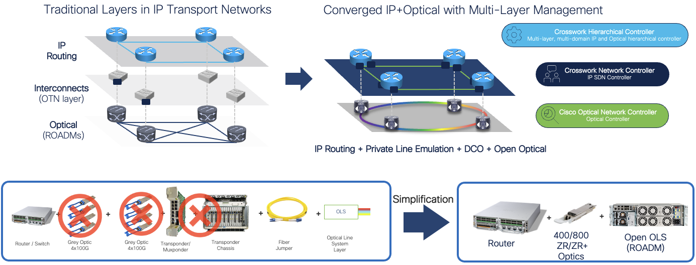
Efficient transport using Routed Optical Networking Cisco’s Routed Optical Network solution simplifies router interconnections across optical fiber, replacing inefficient external transponders with pluggable digital coherent transceivers. Private Line Emulation allows providers to use standard routers to transparently carry Ethernet, OTN/SONET, and Fiber Channel services across an IP network without sacrificing transport layer functionality and resilience.
Simplified network control plane Based on Segment Routing SRv6 or SR-MPLS, the network control plane is simplified scalable to meet even the largest service provider networks.
Built-in network assurance Utilizing advanced functions like Segment Routing Performance Measurement (SR-PM), and Integrated Performance Measurement (IPM), the network itself provides advanced assurance and telemetry functionality. When coupled with Cisco Provider Connectivity Assurance sensors, reporting, and advanced correlation it provides end to end assurance from underlay network to overlay services.
Network device convergence Cisco Routed PON enables providers to provide XGS-PON OLT functionality using a pluggable transceiver. This allows the termination of residential and business PON endpoints on the same routers providing fiber based service termination.
Network infrastructure convergence Carrying multiple services across a single unified network is easier to operate than distinct parallel networks. Agile Metro allows operators to converge residential, business, DCI, and future service types onto a single converged metro network with any to any connectivity.
CUPS based distributed subscriber termination Cisco Cloud Native Broadband Network Gateway (cnBNG) is a CUPS-based solution combining a high-availability cloud native control plane with user-plane elements distributed closer to end users. Distributing the user-plane closer to end users allows for efficient traffic offload vs. traditional BNG deployments where traffic is backhauled to a centralized BNG.
Enhanced security and DDoS protection Security begins with trust and verification of trust. Cisco’s leading NOS security features ensure device authenticity and integrity. Cisco Trust Insights allows providers to monitor and report on the overall trust posture of network devices at all times, alerting on anomalies. Cisco’s Edge Protect DDoS solution distributes DDoS detection and mitigation to every device in the network. The distribution of these function is more efficient and scales higher than traditional centralized DDoS detection and mitigation deployments.
Advanced network automation Simplifying operations requires not only infrastructure simplification but also changes in how networks are operated. The Cisco Crosswork family of network automation software covers the end to end lifecycle of the network. See the section on Network Automation for more detail on how the Agile Metro incorporates these components to help simplify the planning and operation of the network.
Integration across layers Integration across layers includes both underlay/overlay integrations to enable carrying differentiated service traffic across specific engineered paths as well as the ability to correlate higher layer service to underlay infrastructure down to the physical fiber. SD-WAN is one use case covered by Agile Metro where SD-WAN overlay services can be monitored along with the underlay paths carrying the traffic.
Infrastructure network technical overview
The infrastructure portion of the network refers to the building blocks of any high scale service provider network. The hardware, interconnection, and low level control plane protocols are utilized together to build a modern agile scalable network.
The following highlights the key technology building blocks used to build the Agile Metro network.

Hardware Components
Cisco 8000
The Cisco 8000 family is one of the primary hardware components of the Agile Metro design. Cisco 8000 routers provide the lowest power consumption in the industry, all while supporting systems over 200 Tbps and features service providers require. The expanded Silicon One family of ASICs in Agile Metro 1.0 includes the P100 and K100 family of products fulfilling specific roles in the solution.
Agile Metro 1.1 introduces the A100 based access and aggregation devices along with the fully redundant K100 8404-SYS router.
New Agile Services Networking hardware
Agile Services Networking introduces new Silicon One based hardware, simplifying provider deployments with a unified silicon strategy across all parts of the network.
P100 routers and line cards
The P100 Silicon One ASIC provides up to 19.2Tbps of bandwidth. The 8212-48FH-M and 8711-32FH-M single-ASIC fixed routers are validated for edge services, peering, and aggregation roles in the Agile Metro design. P100 line cards are also available for modular systems including the Edge enhanced 88-LC1-12TH24FH-E and 88-LC1-52Y8H-EM. The 88-LC1-52Y8H-EM is the first Silicon One line card offering a high density low speed aggregation with 52 SFP28 ports for 10G and 25G native support. All line cards support MACSec and Class C timing.
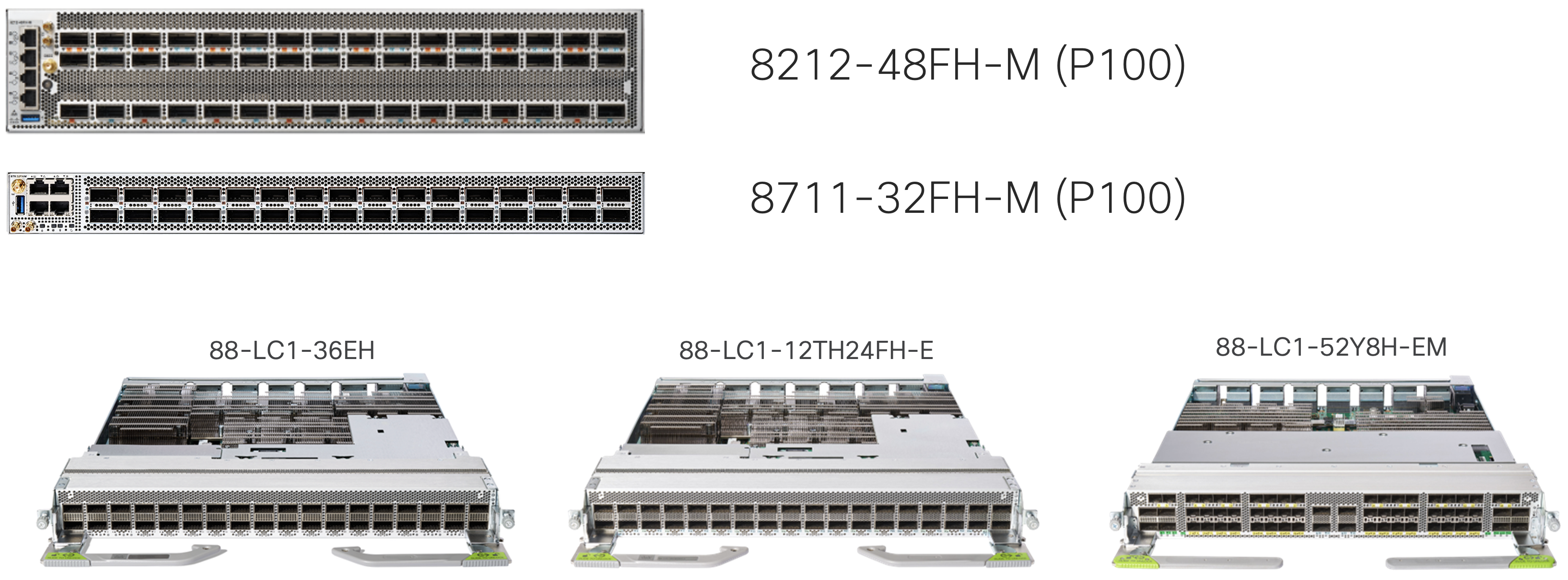
More information on the 8711-32FH-M and 8212-48FH-M routers can be found at:
https://www.cisco.com/c/en/us/products/se/2024/8/Collateral/8700-series-routers-ds.html
K100 routers and line cards
The K100 Silicon One ASIC provides higher scale edge services. The 6.4T ASIC will support advanced Edge service functionality for mobile, business services, Internet, peering, and enterprise use cases. The K100 natively supports MACSEC has an embedded IPSec encryption engine (supported in a future release).
8712-MOD-M
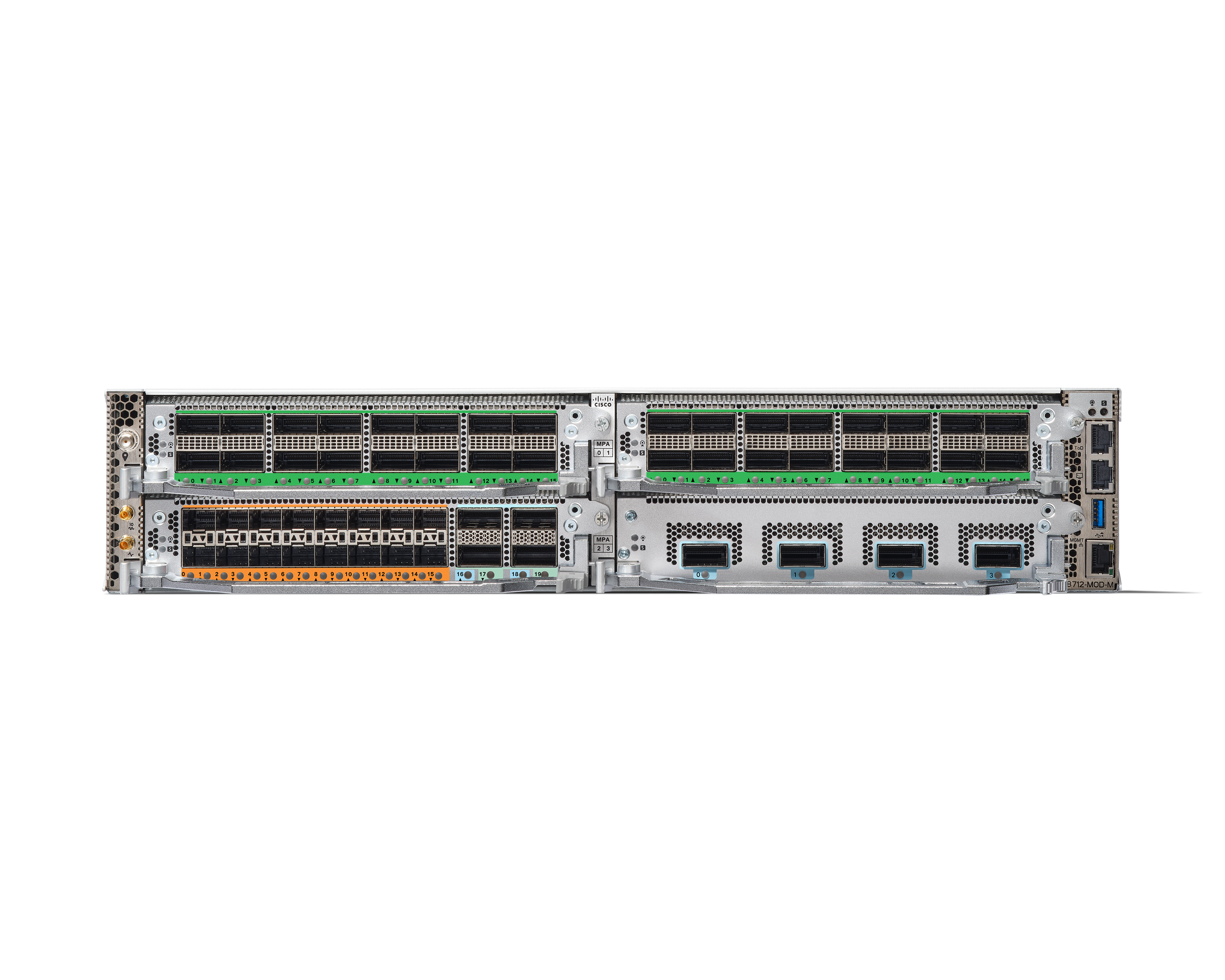
The 8712-MOD-M released with XR 24.4.1 is a modular 2RU 4-slot router using a single ASIC providing 1.6T per slot. The following MPAs will be initially supported ont he 8712-MOD-M. The 8712-MOD-M supports MACSec on all ports with native NPU support for IPSec.
| MPA | Port layout |
|---|---|
| 8K-MPA-4D | 4 400G QSFP56-DD |
| 8K-MPA-16H | 16 QSFP28 |
| 8K-MPA-16Z2D | 16 SFP56 + 4 QSFP56-DD (2x400G or 4x100G/200G) |
| 8K-MPA-18Z1 | 18 SFP56 + 1 QSFP56-DD |
More details on the 8712-MOD-M router can be found at:
https://www.cisco.com/c/en/us/products/se/2024/8/Collateral/8700-series-routers-ds.html
8404-SYS
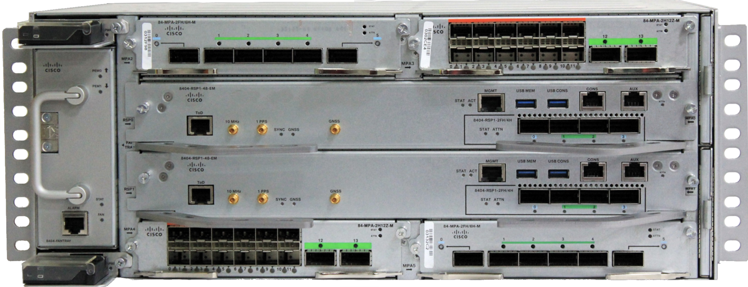
The 8404-SYS released with XR 25.2.1 is a modular fully redundant 4RU 4-slot router providing 1.2T per slot. The 8404-SYS has a 300mm depth ideal for distributed edge applications. The 8404 supports Class C timing and extended temperature ranges. Each RSP on the 8404-SYS has an integrated 400G MPA with two QSFP-DD and two QSFP28 ports. The following MPAs will be supported on the 8404-SYS with each MPA supporting 800G of total bandwidth.
| MPA | Port layout |
|---|---|
| 84-MPA-2FH/6H-M | 2xQSFP-DD + 4xQSFP28 |
| 84-MPA-2H12Z-M | 12xSFP56 + 2xQSFP28 |
More details on the 8404-SYS router can be found at
https://www.cisco.com/c/en/us/products/collateral/routers/8000-series-routers/8404-router-ds.html
A100 routers and line cards
Release 1.1 of Agile Metro introduces the first A100 based router focused on aggregation and access.
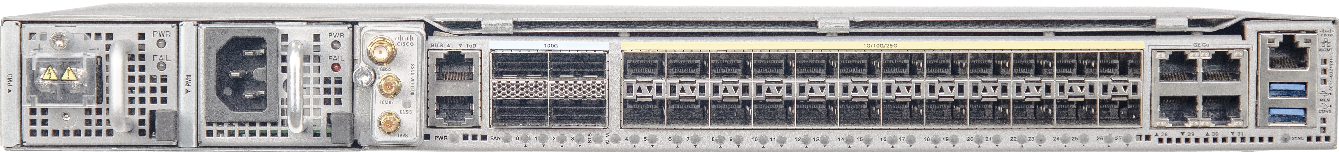
8011-4G24Y4H-I
The 8011-4G24Y4H is a fixed router with 4xRJ45 ports supporting 1G, 24xSFP28 ports supporting 1G, 10G, and 25G and 4xQSFP28 ports supporting 40G or 100G. The router has a depth <300mm and supports I-temp conditions.
ASR 9000
Agile Metro utilizes the ASR 9000 devices using the 5th generation Lightspeed+ NPU in a multi-service PE role, performing high scale L2VPN, L3VPN, peering, and Pseudowire headend termination. The ASR 9000 is also utilized as a user plane in the distributed CUPS architecture for subscriber termination. The solution includes the ASR 9902 and ASR 9903 small form factor modular ASR 9000 routers.

NCS 5504, 5508, 5516 Modular Chassis
The modular chassis version of the NCS 5500 is available in 4, 8, and 16 slot versions for flexible interfaces at high scale with dual RP modules. A variety of line cards are available with 10G, 40G, 100G, and 400G interface support. The NCS 5500 fully supports timing distribution for applications needing high accuracy clocks like mobile backhaul.

NCS 5500 / 5700 Fixed Chassis
NCS 5500 and 5700 routers are supported in the Agile Metro design. They offer a wide range of service and termination aggregation options based on capacity and port needs. These series of routers are utilized across peering, core, DCI, mobile backhaul, and business services use cases.
More information on the NCS 5500 and NCS 5700 family of routers can be found at:
NCS 540 Small, Medium, and Large density routers
The NCS 540 family of routers support residential, mobile, and business services across a wide variety of service provier and enterprise applications, including support for Routed Optical Networking in the QSFP-DD enabled NCS-540 Large Density router. In the Agile Metro design the NCS 540 also supported Routed Passive Optical Networking, combining XGS-PON last mile connections using the Cisco pluggable SFP+ OLT.
More information on the NCS 540 router line can be found at:

Agile Metro Baseline transport
Agile service placement
In an Agile Metro network services can be located at any point within the network, blurring the traditional network boundaries of access, aggregation, edge, and core. These segments in the network may still exist based on geographical boundaries and interconnection, but the “edge” terminating user services can be placed throughout the metro network. The distribution of services enhances overall network scale and resilience.

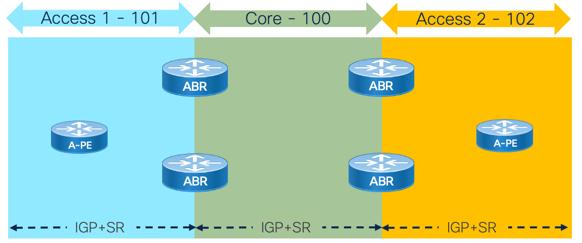
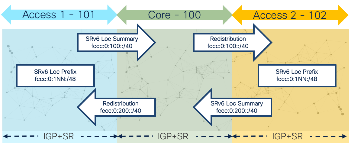
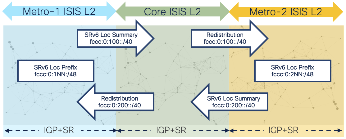
Network domains and IGP structure
Network domains are defined by different criteria. Scale is the primary driver for creating separate network domains but it could be for other reasons such as administrative boundaries or geographic regions. In the case of the Agile network design we will utilize distinct IGP instances at network domain boundary routers (ABRs). Boundary nodes will contain two or more IGP instances. Traffic paths crossing domain boundaries can utilize redistribution, SR-TE using SR-PCE, and traditional overlay options like BGP-LU. SRv6 using aggregation and redistribution is the preferred approach for greenfield networks and networks migrating from legacy MPLS (LDP, RSVP-TE) to Segment Routing.
The Agile Metro achieves network scale by IGP domain separation.
Topology options and PE placement - Inline and non-inline PE
The design is flexible to support edge service placement at different places in the network.

Edge services on a stick
This model can be utilized for scenarios where the Edge service termination is relatively low bandwidth compared to transit traffic and requires utilizing a more sophisticated edge device. In the Agile Metro design this includes cases where Carrier Grade NAT is being used or exception handling for MAP-T traffic.
Fully distributed edge
This model full distributes edge functions so any router within the metro can provide edge user services. A provider may use a fully distributed edge is if the bandwidth, port, or service scale does not exceed that of a single node or pair of nodes.
Edge Fabric
This design creates a scale out fabric which can be placed within a single provider location or utilize WAN connections to create a larger fabric spanning multiple locations. An Edge Fabric is used when providers want the ultimate scale in terminating user services, have a necessity for using specific leaf devices for different services types, or need to create a multi-vendor fabric. See the “Edge Fabric” section of the document for more information on building and managing Edge Fabrics.
Cisco Routed Optical Networking
Routed Optical Networking is a foundational component of the Agile Metro for network operators with their own fiber assets utilizing point to point dark fiber connections or multiplexed DWDM connections. At its basis Routed Optical Networking eliminates redundant hardware and simplifies management through advanced automation. Routed Optical Networking works with all types of optical networks; P2P dark fiber, simplified P2P DWDM using Cisco’s Pluggable OLS with passive multiplexers, and traditional multi-degree ROADMs.
For more information on Cisco’s Routed Optical Networking design please see the following high-level design document:
https://xrdocs.io/design/blogs/latest-routed-optical-networking-hld
Agile Metro Edge Fabric
Agile Services Networking enables providers to build networks in the way that best fits their business and service needs. One deployment method is build an Edge Fabric allowing providers to build a flexible scale-out network providing Edge services. Each leaf node in the fabric can be dedicated to a specific service type or multiple services can be deployed to the same fabric. One key property of the fabric is managing nodes by role and not as individual PE routers. A role is defined by a set of common properties and service termination needs. A fabric may be contained within a single location or span multiple geographic locations, interconnected using Cisco’s Routed Optical Networking solution for simplicity and efficiency.
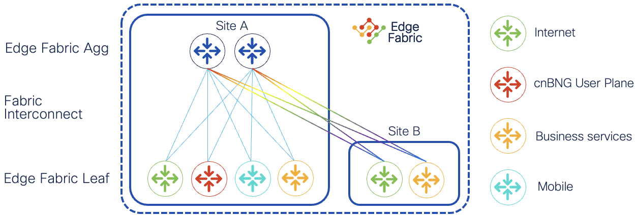
Additional Edge Fabric properties
- Topology-driven group of standard routers
- Uses standard protocols for intra-fabric control-plane and data plane, not proprietary interconnect hardware or proprietary data plane encapsulation
- Service / UNI facing ports are managed on individual leaf devices
- No requirement for homogenous hardware, different devices or even vendors could be used as edge leafs
- Not explicitly a Clos fabric, the spines can be collapsed spine/border nodes, or even terminate some user services
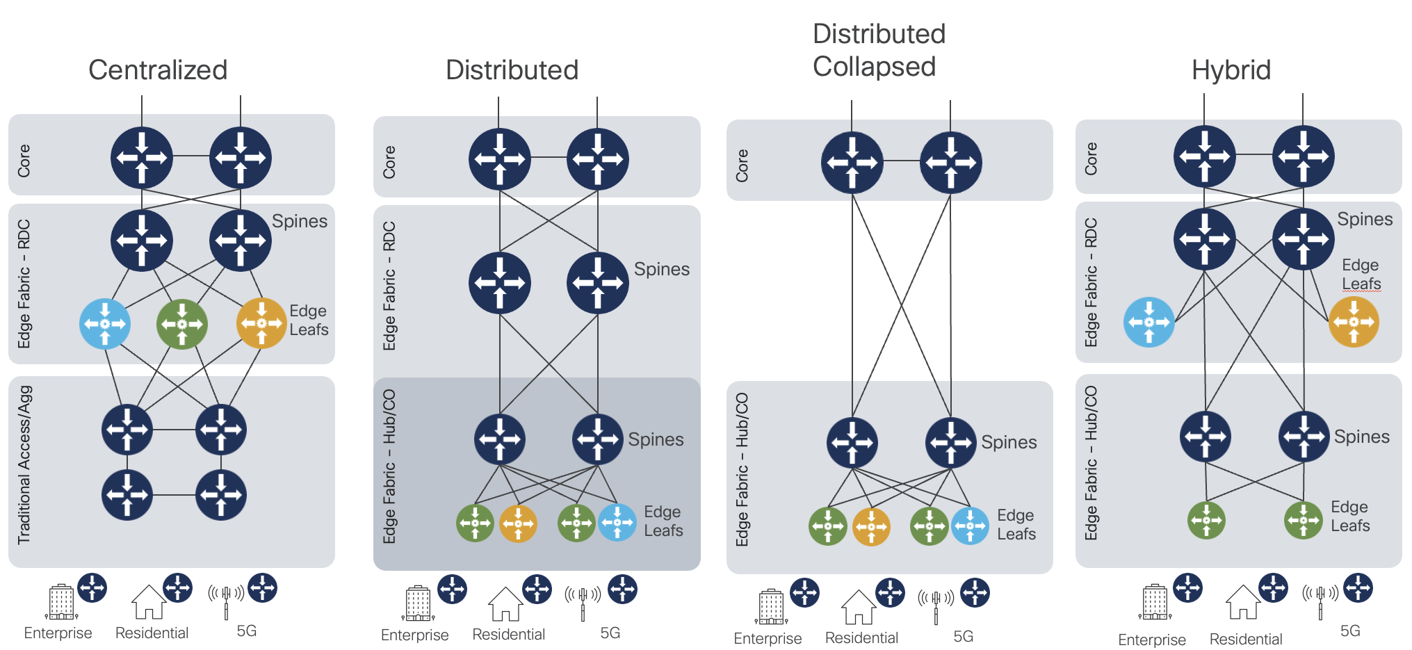
Edge Fabric deployment options
There is also flexibility in how and where the Edge Fabric is deployed in the provider network.
The diagram shows four potential options, but the deployment is primarily based on the provider requirements. The fully distributed edge offers the highest scale and performance, but as interim steps during migration other models may be used.
Recommended Edge Fabric hardware
There is no hard and fast rule about specific hardware deployed in a specific role. Spines should be higher bandwidth and higher port count devices with no service termination on those nodes. If fixed devices are used as spines, the Silicon One P100-based 8212-48FH-M and 8711-32FH-M are ideal spines due to their high 400G and 100G density. P100 routers and line cards also have Edge service capabilities if there is a requirement for placing some services on the spine devices. Edge Leaf devices should be chosen based on UNI port speeds, UNI port bandwidth, and in some cases specific feature support. The NCS 540, NCS 5500/5700, and 8000 series can be utilized for Internet services (DIA), peering, L2VPN, and L3VPN services. In the case of cnBNG user plane the ASR 9000 series satisfies that role.
Edge Fabric control plane
The control plane for the Edge Fabric utilizes standard routing protocols. IS-IS is the recommended IGP protocol to run across the fabric. A large fabric may utilize a separate IGP instance or IS-IS level for nodes with contiguous connectivity. It is expected the leaf nodes in a fabric belong to a single fabric. MP-BGP is utilized as an overlay service protocol, advertising EVPN and L3VPN routes to build both point-to-point and multi-point services. Internet services may be contained within a VRF (Internet in a VRF) or in the global routing table. The design supports using more centralized service route reflectors or using the edge fabric aggregation nodes as fabric route reflectors depending on the scale and redundancy required.
Segment Routing
Segment Routing is a foundational component of Agile Services Networking. The Segment Routing architecture is available with two forwarding planes, IPv6 and MPLS. SRv6 presents a highly scalable and simplified data plane for modern networks. SRv6 is simply IP routing, using IPv6 addresses to represent end nodes as well as end services. The Agile Services Networking solution uses SRv6 with uSID as the primary dataplane, but also utilizes SR-MPLS which is fully supported across all hardware, software, and automation products.
SRv6 Benefits
Scale
One of the main benefits of SRv6 is the ability to build networks at huge scale through address summarization. MPLS networks require a unique label per node be distributed to all nodes requiring mutual reachability. In most cases there is also the requirement of distributing a /32 IP prefix as well. In the MPLS CST design we have the option to eliminate the IP and MPLS label distribution by utilizing a PCE to compute end to end paths. While this method works well and is also available for SRv6 it can lead to a large number of SR-TE or SRv6-TE policies.
SRv6 allows us to summarize domain loopback addresses at IGP or BGP boundaries. This means a domain of 1000 nodes no longer requires advertising 1000 IP prefixes and associated labels, but can be summarized into a single IP advertisement reachable via a simple longest prefix match (LPM) lookup. Networks of tens of thousands of nodes can now provide full reachability with very few IPv6 routes.
Simplified Forwarding
In SRv6, if a node is not a terminating node it simply forwards the traffic using IPv6 IP forwarding. This means nodes which are not SRv6 aware can also participate in a SRv6 network.
Forwarding in SRv6 follows the semantics of simple IPv6 routing. The destination is always identified as an IPv6 address. In the case of an SRv6 packet without an additional SRH, traffic is routed to the endpoint destination node hop by hop based on normal destination based prefix lookups. In the case of a SRH, the SRH is only processed by a node if it is the destination address in the outer IPv6 header. If the node is the last SID in the SID list it will pop the SRH and process the packet further. If the node is not the last SID in the SID list it will replace the outer IPv6 destination address with the next IPv6 address in the SID list.
Forwarding and service congruency
As you will see in the services section, the destination IPv6 address in SRv6 is the service endpoint. Coupled with the simple forwarding this aids in troubleshooting and is much easier to understand than the MPLS layered service and data plane.
Control Plane design
Control plane elements
IS-IS as IGP
Simplicity is key when deploying modern networks. Legacy networks include a base IGP protocol for route distribution along with an overlay protocol used for MPLS label distribution. The Agile Services Networking design utilizes a single IGP protocol, IS-IS, covering IPv4 and IPv6.
IS-IS deployment and network segmentation
Segmentation of networks may be done at the IGP instance/process level for scale or administrative reasons. The ability to aggregate and redistribute SRv6 (It’s just IPv6!) prefixes across IS-IS area or instance boundaries allows networks to scale to millions of routers with relatively few prefixes across the network. SRv6 retains Flex-Algo information across IS-IS instance boundaries.
In the case of SR-MPLS inter-area traffic engineering is solved using SR-PCE, Cisco’s scalable Path Computation Element.
Segment Routing
As mentioned in the building block section above, Segment Routing is a foundational element for building a modern services network. It simplifies the control and data plane of the network, eliminating legacy protocols such as LDP and RSVP-TE while providing additional capabilities for traffic engineering, network assurance, and network resiliency.
SR-MPLS or SRv6 Segment Identifiers (SIDs) are distributed using IS-IS in both intra-domain and inter-domain use cases.
Segment Routing Flexible Algorithms (Flex-Algo)
A powerful tool used to create traffic engineered Segment Routing paths is SR Flexible Algorithms, better known as SR Flex-Algo. Flex-Algo assigns a specific set of “algorithms” to a Segment. The algorithm identifies a specific computation constraint the segment supports. There are standards based algorithm definitions such as least cost IGP path and latency, or providers can define their own algorithms to satisfy their business needs. Agile Services Networking supports computation of Flex-Algo paths in intra-domain and inter-domain deployments. Flex-Algo limits the computation of a path to only those nodes participating in that algorithm. This gives a powerful way to create multiple network domains within a single larger network, constraining an SR path computation to segments satisfying the metrics defined by the algorithm. As you will see, we can now use a single node SID to reach a node via a path satisfying an advanced constraint such as delay.
Operators can solve most traffic engineering use cases with Flex-Algo. Capabilities of Flex-Algo are continually being enhanced, supporting additional metrics and constraints for path computation. In XR 24.4.1 the following metrics and constraints are supported.
Flex-Algo Metrics
- Delay
- Delay utilizes the measured or statically configured delay of each link to compute an end to end lowest latency path. Delay values are computed or defined using SR Performance Measurement.
Generic - The generic metric type is used by operators to build a custom topology based on their own metrics. The generic metric for each link is defined in the IS-IS configuration for each link. The Flex-Algo topology will only include nodes/links with the generic metric defined, and will follow the lowest cost path using those user-defined metrics. TE: The TE metric is an additional metric which can be assigned to each link. The TE metric is advertised in the standard IS-IS traffic engineering TLVs.
Flex-Algo Constraints
Affinity: Affinity uses standard unidirectional traffic engineering affinities (groups) to include or exclude links from the topology. IOS-XR also supports reverse affinities, meaning if the affinity is being sent from node B to A, A will take that link into account when computing the Flex-Algo. One use case is if an affinity is being applied by the remote node on the link due to packet errors.
Minimum Bandwidth: The minimum bandwidth metric is uses to prune links below a certain bandwidth value. This is useful for networks with a mix of high and low speed links to ensure traffic does not take a low speed path. An example is a network with 10G access rings connected to a higher speed aggregation network. High speed traffic between aggregation locations should never traverse the access rings, and this is easily achievable using the minimum bandwidth constraint.
Maximum Delay: Maximum delay uses the measured or statically set SR-PM delay values to prune high delay links from the network. While the delay metric will calculate the lowest delay path, this will ensure that path never takes high delay links.
Path Computation across SR Flex-Algo Network
Flex-Algo works by creating a separate topology for each algorithm. By default, all links interconnecting nodes participating in the same algorithm can be used for those paths. If the algorithm is defined to include or exclude specific link affinities, the topology will reflect it. A SR-TE path computation using a specific Flex-Algo will use the Algo’s topology for end the end path computation. It will also look at the metric type defined for the Algo and use it for the path computation. Even with a complex topology, a single SID is used for the end to end path, as opposed to using a series of node and adjacency SIDs to steer traffic across a shared topology. Each node participating in the algorithm has adjacencies to other nodes utilizing the same algorithm, so when an incoming SRv6 locator or MPLS label matching the algo SID enters, it will utilize the path specific to the algorithm. On-demand SR-TE policies can also use a specific algorithm.
Traffic Engineering (Tactical Steering) – SR-TE Policy
Segment Routing provides a simple and scalable way of defining an end-to-end application-aware traffic engineering path known as an SR-TE Policy. The SR-TE Policy expresses the intent of the applications constraints across the network. The path computation will minimize the number of segments required to build the end to end path across the network, simplifying deploying and increasing the supported path length.
In the Agile Metro design, SR-TE can be utilized for both IPv6 and MPLS dataplanes for more advanced traffic engineering use cases.
Path computation of the end to end SR-TE path is carried out either on the head-end node or by using a PCE (Path Computation Element). SR-TE policies can be persistently configured on the head-end node or computed on-demand using Cisco “On-Demand Next Hop” or ODN feature.
Circuit Style Segment Routing (SR-MPLS)
Circuit Style Segment Routing (CS-SR) is another Cisco advancement bringing TDM circuit like behavior to SR-TE Policies. These policies use deterministic hop by hop routing, co-routed bi-directional paths, hot standby protect paths with end to end liveness detection, and bandwidth guaranteed services. Standard Ethernet services not requiring bit transparency can be transported over a Segment Routing network similar to OTN networks without the additional cost, complexity, and inefficiency of an OTN network layer.
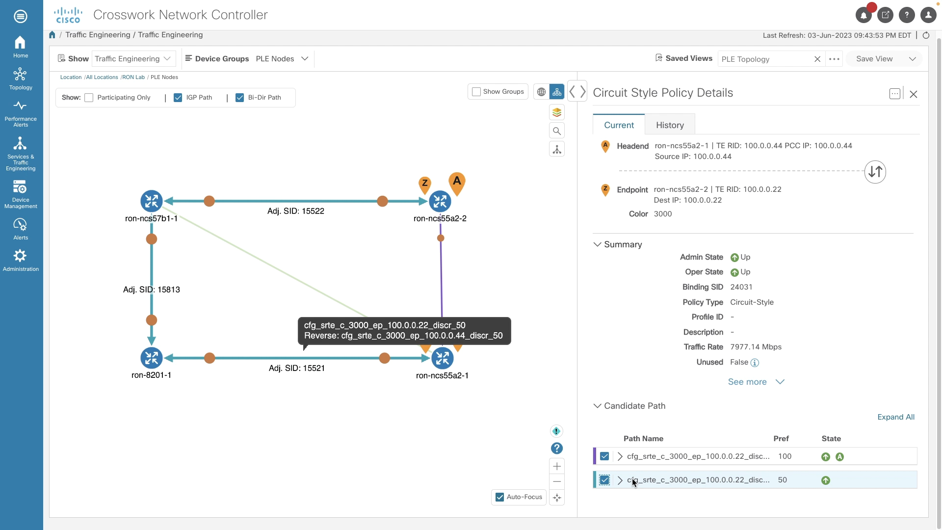
Circuit-Style SR-TE with Bandwidth Admission Control using CNC Circuit Style Manager
Crosswork Network Controller Circuit Style Manager provides Bandwidth Admission Controller and guaranteed bandwidth paths for Circuit-Style Policies. CNC also supports full provisioning, monitoring, and visualization of Circuit-Style SR-TE Policies.
Segment Routing Path Computation Element (SR-PCE)
Segment Routing Path Computation Element, or SR-PCE, is a Cisco Path Computation Engine (PCE) and is implemented as a feature included as part of Cisco IOS-XR operating system. The function is typically deployed on Cisco’s virtual router, the XRv-9000 as it involves control plane operations only. The SR-PCE gains network topology awareness from BGP-LS advertisements received from the underlying IGP network. Such knowledge is leveraged by the embedded multi-domain computation engine to provide optimal path information to Path Computation Element Clients (PCCs) using the Path Computation Element Protocol (PCEP).
The PCC is the device where the service originates (PE) and therefore it requires end-to-end connectivity over the segment routing enabled multi-domain network.
SR-MPLS, SRv6, and Unified MPLS (BGP-LU) Co-existence
In the Agile Metro design validation is performed for the co-existence of services using BGP Labeled Unicast transport for inter-domain forwarding and those using SR-MPLS and SRv6. Many networks deployed today have an existing BGP-LU design which may not be easily migrated to SR, so graceful introduction between the two transport methods is required.
Network timing
Modern infrastructure services require stable timing. Distributing timing through the network decreases overall cost by not requiring timing equipment at end locations. Components used in the Agile Metro design all support Precision Timing Protocol (PTP) timing distribution and in most cases support Class C timing accuracy. It is recommended to use G.8257.1 when possible to maintain the highest level of accuracy across the network. IOS-XR fully supports G.8275.1 to G.8275.2 interworking, allowing the use of different profiles across the network. Synchronous Ethernet (SyncE) is also recommended across the network to maintain stability when timing to the PRC.
Quality of Service (Update for 8000)
Overview
Quality of Service is of utmost importance in today’s multi-service converged networks. The Agile Metro design has the ability to enforce end to end traffic path SLAs using Segment Routing Traffic Engineering. In addition to satisfying those path constraints, traditional QoS is used to make sure the PHB (Per-Hop Behavior) of each packet is enforced at each node across the converged network.
NCS 540, 560, 5500, and 5700 QoS
Full details of the NCS 540 and 5500 QoS capabilities and configuration can be found at: https://www.cisco.com/c/en/us/td/docs/iosxr/ncs5500/qos/24xx/configuration/guide/b-qos-cg-ncs5500-24xx.html
The NCS platforms utilize the same MQC configuration for QoS as other IOS-XR platforms but based on their hardware architecture use different elements for implementing end to end QoS. On these platforms ingress traffic is:
- Matched using flexible criteria via Class Maps
- Assigned to a specific Traffic Class (TC) and/or QoS Group for further treatment on egress
- Has its header marked with a specific IPP, DSCP, or MPLS EXP value
Traffic Classes are used internally for determining fabric priority and as the match condition for egress queuing. QoS Groups are used internally as the match criteria for egress CoS header re-marking. IPP/DSCP marking and re-marking of ingress MPLS traffic is done using ingress QoS policies. MPLS EXP for imposed labels can be done on ingress or egress, but if you wish to rewrite both the IPP/DSCP and set an explicit EXP for imposed labels, the MPLS EXP must be set on egress.
The priority-level command used in an egress QoS policy specifies the egress transmit priority of the traffic vs. other priority traffic. Priority levels can be configured as 1-7 with 1 being the highest priority. Priority level 0 is reserved for best-effort traffic.
Please note, multicast traffic does not follow the same constructs as unicast traffic for prioritization. All multicast traffic assigned to Traffic Classes 1-4 are treated as Low Priority and traffic assigned to 5-6 treated as high priority.
Cisco 8000, 8010, 8600, and 8700 QoS
The semantics of the QoS configuration of the Cisco 8000 follows similar configuration guidelines as the NCS 540, 5500, and NCS 5700 series devices. It utilizes the same traffic class structure, QoS groups, and priority level behavior to mark traffic and apply queuing behavior. Detailed documentation of 8000 series QoS including platform dependencies can be found at:
https://www.cisco.com/c/en/us/td/docs/iosxr/cisco8000/qos/25xx/configuration/b-qos-cg-8k-25xx.html
Hierarchical Edge QoS
Hierarchical QoS enables a provider to set an overall traffic rate across all services, and then configure parameters per-service via a child QoS policy where the percentages of guaranteed bandwidth are derived from the parent rate
Cisco 8000 H-QoS Platform Support
Hierarchical QoS will be available on the Cisco 8404, 8010, and 8700 series routers in a future Agile Metro release.
NCS 5500/5700 H-QoS platform support
NCS platforms support 2-level and 3-level H-QoS. 3-level H-QoS applies a policer (ingress) or shaper (egress) to a physical interface, with each sub-interface having a 2-level H-QoS policy applied. Hierarchical QoS is not enabled by default on the NCS 540 and 5500 platforms. H-QoS is enabled using the hw-module profile qos hqos-enable command. Once H-QoS is enabled, the number of priority levels which can be assigned is reduced from 1-7 to 1-4. Additionally, any hierarchical QoS policy assigned to a L3 sub-interface using priority levels must include a “shape” command.
Hierarchical QoS will be available on the Cisco 8010 and 8700 series routers in a future Agile Metro release.
Agile Services Core QoS mapping with five classes
QoS designs are typically tailored for each provider. Ideally a network will utilize as few core QoS classes as necessary. Many modern networks carrying high bandwidth residential traffic could utilize just two classes, Best Effort and Higher Priority. Below is an example of a 5-level QoS design which can fit most provider needs. The design covers transport of both unicast and multicast traffic. If a provider does not need 5 classes, this can always be reduced.
| Traffic Type | Core Marking | Core Priority | Comments |
|---|---|---|---|
| Network Control | EXP 6 | Highest | Underlay network control plane |
| Low latency | EXP 5 | Highest | Low latency service, consistent delay |
| High Priority 1 | EXP 3 | Medium-High | High priority service traffic |
| Medium Priority / Multicast | EXP 2 | Medium priority and multicast | |
| Best Effort | EXP 0 | General user traffic |
Multicast
Multicast traffic distribution can still be an important component in service provider networks. Multicast is often used for video distribution and certain services requiring distribution communication between endpoints.
SRv6 Multicast Deployment
SRv6 unicast services seamlessly co-exist with traditional deployed multicast technology such as native PIM-SM/PIM-SSM, IP based mVPN, SR-MPLS Tree-SID, and mLDP. Multicast traffic today is not encapsulated and delivered via SRv6, but in future Agile Metro releases we will incorporate new Cisco-led technologies to bring together a unified control and data-plane using SRv6.
L3 Multicast using SR-MPLS Tree-SID
Tree SID Diagram

Tree-SID Overview
Tree-SID utilizes the programmability of SR-PCE to create and maintain an optimized multicast tree from source to receiver across an SR-only IPv4 network. Each node in the network maintains a session to the same set of SR-PCE controllers. The SR-PCE creates the tree using PCE-initiated segments. TreeSID supports advanced functionality such as TI-LFA for fast protection and disjoint trees.
Static Tree-SID
Multicast traffic is forwarded across the tree using static S,G mappings at the head-end source nodes and tail-end receiver nodes. Providers needing a solution where dynamic joins and leaves are not common, such as broadcast video deployments, can be benefit from the simplicity static Tree-SID brings, eliminating the need for distributed BGP mVPN signaling. Static Tree-SID is supported for both default VRF (Global Routing Table) and mVPN.
Please see the CST 3.5+ Implementation Guide for static Tree-SID configuration guidelines and examples.
Dynamic Tree-SID using BGP mVPN Control-Plane
IOS-XR supports using fully dynamic signaling to create multicast distribution trees using Tree-SID. Sources and receivers are discovered using BGP auto-discovery (BGP-AD) and advertised throughout the mVPN using the IPv4 or IPv6 mVPN AFI/SAFI. Once the source head-end node learns of receivers, the head-end will create a PCEP request to the configured primary PCE. The PCE then computes the optimal multicast distribution tree based on the metric-type and constraints specified in the request. Once the Tree-SID policy is up, multicast traffic will be forwarded using the tree by the head-end node. Tree-SID optionally supports TI-LFA for all segments, and the ability to create disjoint trees for high available applications.
All routers across the network needing to participate in the tree, including core nodes, must be configured as a PCC to the primary PCE being used by the head-end node.
Please see the Agile Services Networking Implementation Guide for more information on implementing SR-MPLS Tree-SID.
L3 IP Multicast and mVPN using mLDP
The Agile Metro design supports using mLDP for multicast distribution when using SR-MPLS or SRv6 for unicast transport.
Using BGP signaling adds additional scale to the network over in-band mLDP signaling and fits with the overall design goals of CST. More information about deployment of profile 14 can be found in the Agile Metro implementation guide. The Agile Services Networking design supports mLDP-based label switched multicast within a single doman and across IGP domain boundaries. In the case of the Agile Metro design multicast has been tested with the source and receivers on both access and ABR PE devices.
| Supported Multicast Profiles | Description |
|---|---|
| Profile 6 | mLDP VRF using in-band signaling |
| Profile 7 | mLDP global routing table using in-band signaling |
| Profile 14 | Partitioned MDT using BGP-AD and BGP c-multicast signaling |
Profile 14 is recommended for all service use cases and supports both intra-domain and inter-domain transport use cases.
Agile Metro subscriber edge components
Cloud Native Broadband Network Gateway
Cloud Native Broadband Gateway (cnBNG) represents a fundamental shift in how providers build converged access networks by separating the subscriber BNG control-plane functions from user-plane functions. CUPS (Control/User-Plane Separation) allows the use of scale-out x86 compute for subscriber control-plane functions, allowing providers to place these network functions at an optimal place in the network, and also allows simplification of user-plane elements. This simplification enables providers to distribute user-plane elements closer to end users, optimizing traffic efficiency to and from subscribers.
Cisco cnBNG Architecture
Cisco’s cnBNG supports the BBF TR-459 standards for control and user plane communication. The State Control Interface (SCi) is used for programming and management of dynamic subscriber interfaces including accounting information. The Control Packet Redirect Interface (CPRi) as its name implies redirects user packets destined for control-plane functions from the user plane to control plane. These include: DHCP DORA, DHCPv6, PPPoE, and L2TP. More information on TR-459 can be found at https://www.broadband-forum.org/marketing/download/TR-459.pdf
cnBNG Control Plane
The cloud native BNG control plane is a highly resilient scale out architecture. Traditional physical BNGs embedded in router software often scale poorly, require complex HA mechnaisms for resiliency, and are relatively painful to upgrade. Moving these network functions to a modern Kubernetes based cloud-native infrastructure reduces operator complexity providing native scale-out capacity growth, in-service software upgrades, and faster feature delivery.
cnBNG User Plane
The cnBNG user plane in Agile Metro 1.1 is provided by Cisco ASR 9000 routers. The routers are responsible for terminating subscriber sessions (IPoE/PPPoE), communicating with the cnBNG control plane for user authentication and policy, applying subscriber policy elements such as QoS and security policies, and performs subscriber routing. Fixed and modular platforms are supported
Cisco Routed Passive Optical Networking
Cisco’s Routed Optical Networking has helped reduce cost, space, and power by replacing external transponder hardware with a pluggable transceiver. Cisco Routed Passive Optical Networking extends this concept by replacing a dedicated separate XGS-PON OLT chassis with a pluggable OLT used in Cisco routers. This enables providers to reduce the power and space footprint in remote locations and converge XGS-PON OLT function on routers providing other services such as fiber based L2VPN/L3VPN business services or mobile backhaul.
Cisco Routed PON Components
Cisco Routed PON pluggable OLT
The key component to device level convergence with Cisco RPON is using a pluggable XGS-PON Optical Line Terminal. This allows the OLT to be used in a standard IOS-XR router, eliminating the need for the additional OLT.

Cisco Routed PON controller
The Cisco Routed PON controller runs directly on the IOS-XR router hosting the pluggable OLT. The software is distributed as part of the IOS-XR software distribution and runs as a third party container within IOS-XR’s application hosting infrastructure. It provides the interface between the Routed PON manager and the pluggable OLT.
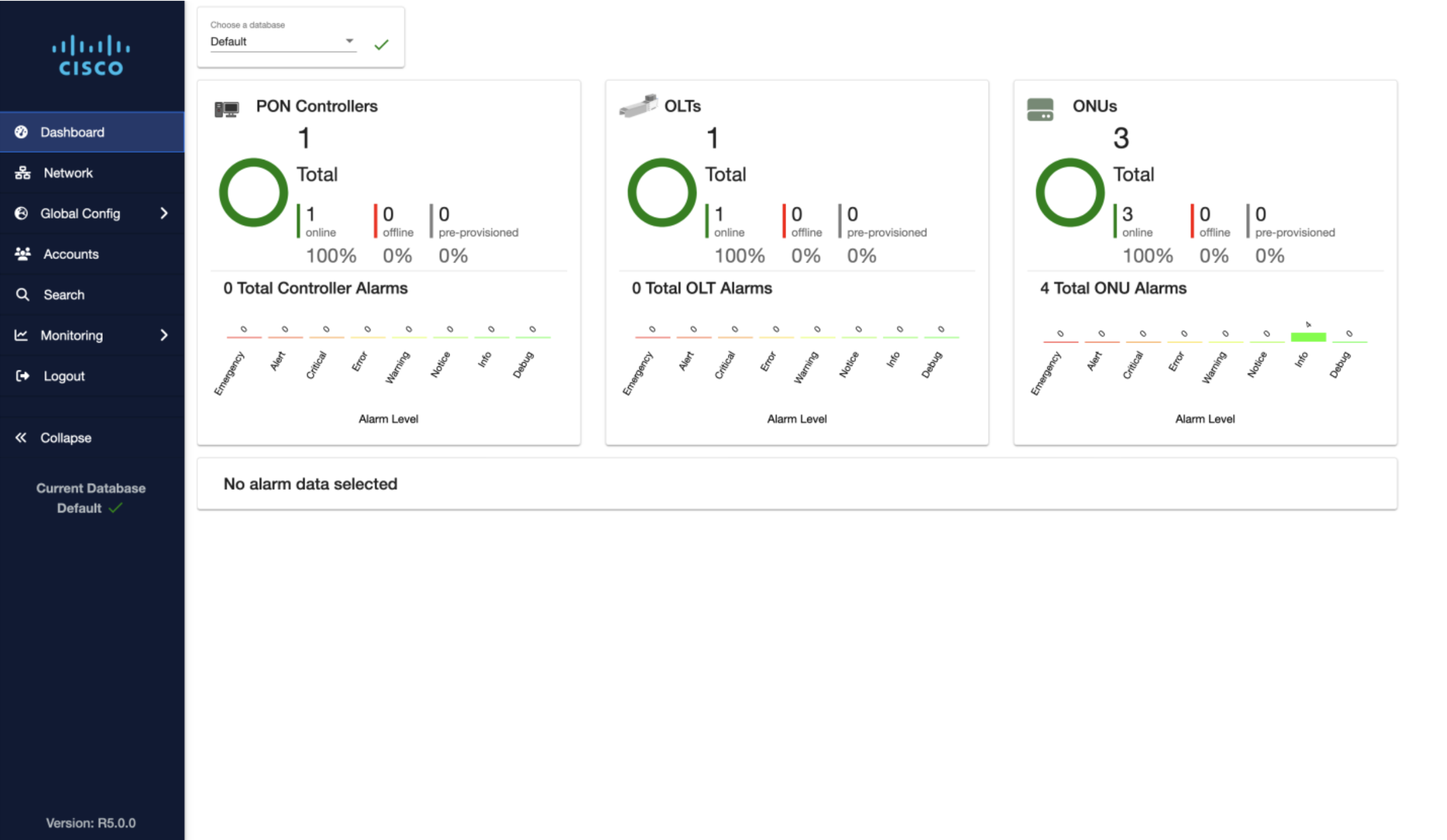
Cisco Routed PON manager
The Cisco Routed PON manager provides all of the functionality to manage pluggable OLTs deployed in the field. Provisioning of services is performed either via UI or API via the PON Manager. It also serves as a single point of monitoring for the OLT/ONU infrastructure. The PON Manager has a standard interface via NETCONF used for managing all aspects of the PON network.
Agile Metro use cases
Service Provider networks must adopt a flexible design satisfying
any to any connectivity, without compromising in stability and availability. Moreover, transport programmability is essential to bring SLA awareness into the network.
The goal of the Agile Metro is to provide a flexible network blueprint that can be easily customized to meet customer specific requirements. This blueprint must adapt to carry any service type, for example
cable access, mobile, and business services over the same converged network infrastructure. The following sections highlight the use cases and the components of the design used in building those solutions.
Collapsed use cases
While we describe different use cases it doesn’t mean multiple use cases cannot be converged on a single device. There are a number of benefits to functional separation in networks but there are times due to location size it isn’t cost or operational effective to place dedicated routers for each role at a location. Modern Cisco routers are built to handle a wide variety of features covering many use cases.
Core
Core routers typically serve a single purpose in providing high density and high bandwidth aggregation and connectivity between other core routers. The 8000 series is ideal for these applications at an industry leading power utilization.
Peering and content delivery
Internet peering refers to connecting to the global Internet as well as other organizations to exchange routing information and ultimately optimize traffic delivery between networks. The full global routing table now exceeds 1M IPv4 prefixes and 256K IPv6 prefixes, requiring devices with scale to support both internal routing tables as well as the default-free global table.
Cisco’s Agile Services Networking solves peering and content delivery needs through both hardware, software features, and automation.
- High RIB/FIB scale across platforms right sized for content and peering deployments
- Segment Routing traffic engineering
- BGP Flowspec support across platforms
- Embedded DDoS protection using Cisco’s DDoS Edge Protect
- Simplified BGP monitoring using Crosswork Cloud Network Insights
- Simplified peering analysis using Crosswork Cloud Traffic Analytics
AI connectivity
Artificial Intelligence is radically changing how enterprises and users operate. Network operators play a crucial role in how AI endpoints and functions will interconnect between each other and reach end users. In its simplest form, this is high bandwidth connectivity between AI cluster components, ideally delivered over a simplified IP and optical network such as one provided by Cisco’s Routed Optical Networking solution.
As agentic AI becomes the standard, it will require low latency connectivity between the components agents are communicating between to deliver a high performance product to applications and end users.
Business edge including mobile backhaul
The Agile Metro design continues to support high performance mobile backhaul and traditional L2VPN and L3VPN business services. Delivering these products at high scale
End to End Timing Validation
End to end timing using PTP with profiles G.8275.1 and G.8275.2 have been validated in the Agile Metro design. All Cisco hardware validated in the design supports at least Class B network timing with new A100, K100, and P100 8000 series routers supporting Class C. Best practice configurations are available in the online configurations and Agile Services Networking Implementation Guide. It is recommended to use G.8257.1 when possible to main the highest level of accuracy across the network.
IOS-XR fully supports G.8275.1 to G.8275.2 interworking, allowing the use of different profiles across the network. Synchronous Ethernet (SyncE) is also recommended across the network to maintain stability when timing to the PRC.
Network assurance
SR Performance Measurement
The network itself can perform dynamic performance measurement between any two endpoints in the network. Performance measurement includes delay and loss calculations. It is recommended SR-PM be enabled on all logical links across the network.
Dynamic Link Performance Measurement
SR-PM supports dynamic measurement of one-way and two-way delay and loss on logical links. The delay measurement feature utilizes TWAMP-Lite as the transport mechanism for probes and responses. PTP is a requirement for accurate measurement of one-way latency across links and is recommended for all nodes. In the absence of PTP a “two-way” delay mode is supported to calculate the one-way link delay.
Legacy hardware also now supports a software CPU based timestamp method to enable SR-PM delay measurements for hardware without PTP timing hardware.
Delay and loss measurement is also available for SR-TE Policy paths to give the provider an accurate latency and loss measurement for all services utilizing the SR-TE Policy. This information is available through SR Policy statistics using the CLI or model-driven telemetry. The latency measurement is done for all active candidate paths.
Delay and Loss anomaly detection
It is possible to set thresholds for both delay and loss and trigger behaviors based on the type of resource being monitored using SR-PM. In the case of a SR-Policy, a candidate path can be deactivated if the delay or loss exceeds the configured thresholds. In the case of a logical link, the IGP advertising the link will set the “A” or anomaly bit for the link. When a receiving node receives the IGP link state data with the A bit set, it can raise the IGP cost on the link.
The “anomaly-check” command is used for delay thresholds, and the “anomaly-loss” command is used for loss thresholds.
Sample SR-PM configuration
performance-measurement
 interface TenGigE0/0/0/5
  delay-measurement
  !
 !
 interface TenGigE0/0/0/23
  delay-measurement
  !
 !
 interface HundredGigE0/0/1/0
  delay-measurement
  !
 !
 interface HundredGigE0/0/1/1
  delay-measurement
  !
 !
 delay-profile interfaces default
  advertisement
   accelerated
    threshold 25
   !
   anomaly-check upper-bound 1000 lower-bound 100
   periodic
    interval 120
    threshold 10
   !
   anomaly-loss upper-bound 20 lower-bound 10
  !
  probe
   measurement-mode two-way
   protocol twamp-light
  !
 !
 protocol twamp-light
  measurement delay
   unauthenticated
    querier-dst-port 12345
Security
Security overview
Security is a top priority in building modern networks. Cisco and the Agile Metro design use a defense in depth strategy. Each layer of security is addressed starting at the initial manufactured hardware and continuing across all layers up to the service layer. Application layer security is not covered by the Agile Metro infrastructure and services design but is covered by additional Cisco Security products.
Cisco DDoS Edge Protection
Cisco’s Edge DDoS Protect presents an innovative solution providing fully distributed DDoS protection for all places in the network.
The key component of DDoS Edge Protect is a small, lightweight, and containerized DDoS detection engine, running inside Cisco IOS XR operating system on selected Cisco routers. As a feature of the router itself, the solution provides out-of-path, full detection, and granular mitigation capabilities against volumetric DDoS attacks. This allows the router to become the first line of defense against DDoS attacks where attack traffic can be blocked in-place and no longer needs to be backhauled to dedicated scrubbing infrastructure. This gives operators the opportunity to extend DDoS protection to the edge of the network which would otherwise be cost-prohibitive and negatively impacting the application latency and the quality of experience. The overall scrubbing capacity of the network is also increased since every router now has DDoS scrubbing capability.
You can apply this solution to the existing install base and to new router deployments without requiring any additional hardware.

DDoS Edge Protect operation

The above diagram explains the operation of Cisco DDoS Edge Protect. Standard Netflow data is encapsulated in gRPC messages to the internal Edge Protect agent. The data is analzyed by the agent and controller to determine the attack and the proper mitigation technique. In most cases a granular ACL can be deployed to the router to mitigate a volumetric attack, dropping traffic based on
Example ACL Deployment
RP/0/RP0/CPU0:cst-8712-pa2#show run ipv4 access-list myACL
ipv4 access-list myACL
 1 deny udp any eq 3000 host 17.2.1.2 eq domain packet-length eq 228
 6 deny tcp any eq 3400 host 18.19.1.2 eq www match-all -established -fin -psh +syn -urg packet-length eq 1178
 1301 permit ipv4 any any
DDoS Edge Protection management
The management of the on-router DDoS Edge Protect containers is done through Cisco’s Edge Protect DDoS controller. The controller manages the deployment of containers to the routers and acts as a single pane of glass for monitoring the current state of the overall solution. The software tracks ongoing attacks and mitigations deployed.
MACSec support
Cisco A100, P100, and K100 8000 routers such as the 8212-32FH-M, 8712-MOD-M, and 8011-4G24Y4H support MACSec across all ports. This allows providers to build end to end networks from access to core protected from man in the middle link snooping.
IPSec support
Cisco A100 and K100 8000 routers such as the 8712-MOD-M and 8011-4G24Y4H contain built-in ASIC support for IPSec. IPSec features and functionality will be enabled in future releases of IOS-XR and Agile Metro.
Agile network automation
Network automation in Agile Services Networking Network automation plays a key role in how Agile networks are built and managed. Cisco’s Crosswork family of network automation gives network operators the ability to easily deploy network infrastructure, manage multi-layer network services, and provide advanced levels of network assurance. This blog will introduce just a few aspects of Cisco’s service provider network automation capabilities, please see https://www.cisco.com/c/en/us/products/cloud-systems-management/crosswork-network-controller/index.html for an in-depth view of all of the capabilities.
IP network management using Cisco Crosswork Network Controller
Crosswork Network Controller provides a platform for UI and API based network management. Agile Metro 1.1 utilizes CNC 7.1. CNC 7.1 supports the following major use cases:
- Device Element Management with fault, alarm, software management, and day-1 configuration deployment using parameterized templates
- Device performance measurement (DPM) to monitor critical network resources such as traffic utilization, PTP status, and coherent optics performance using advanced telemetry methods and user-defined alert thresholds
- Advanced network slicing functionality combining policy driven services, underlay traffic engineering, and QoS
- Workflow manager allows users to create repeatable network automation tasks
- Bandwidth optimization using tactical traffic engineering
- Rich visualization of all aspects of network topology including L2VPN and L3VPN services and SRv6, SR-MPLS, and RSVP-TE transport
- Provisioning of overlay network services and TE paths
More information on Crosswork Network Controller can be found at: https://www.cisco.com/c/en/us/products/cloud-systems-management/crosswork-network-controller/index.html
Fleet upgrade functionality
CNC 7.1’s EMS capability includes the ability to easily manage device software across a variety of network roles. Devices can easily be selected by their properties and upgrades scheduled.

Network slicing
L2VPN Service Provisioning and Visualization
Crosswork Network Controller supports UI and API based provisioning of EVPN-VPWS services using the IETF L2NM standard model. Once services are provisionined they are visualized using the CNC topology UI along with their underlying SR-TE policies, if applicable.

L3VPN Service Provisioning and Visualization
Crosswork Network Controller supports UI and API based provisioning of L3VPN
services using the IETF L3NM standard model. Once services are provisionined they are visualized using the CNC service topology UI along with their underlying SR-TE policies, if applicable.

Crosswork Automated Assurance
In addition to provisioning, monitoring of all transport infrastructure is also supported including advanced service assurance for xVPN services. Service assurance checks all aspects of the network making up the service along with realtime Y.1731 measurements to ensure the defined SLA for the service is met.


The figure below shows an example of a degraded service where the measured one-way latency on the end to end path of 1680uS has exceeded the SLA of 500uS.

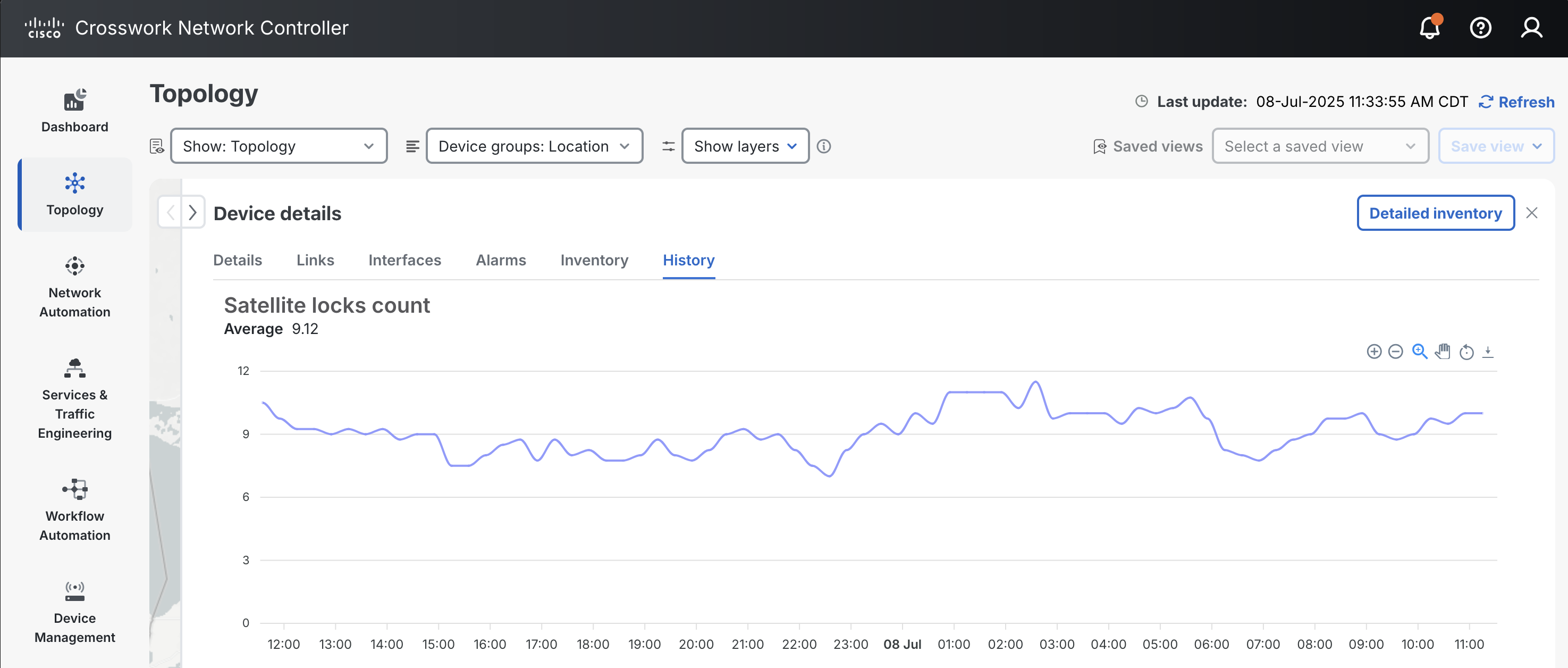
Device Performance Measurement
Device performance measurement policies are used to collect network data from specified devices. Traffic data is collected from all supported devices by default. Advanced performance policies can be enabled for specific technologies on a subset of devices.
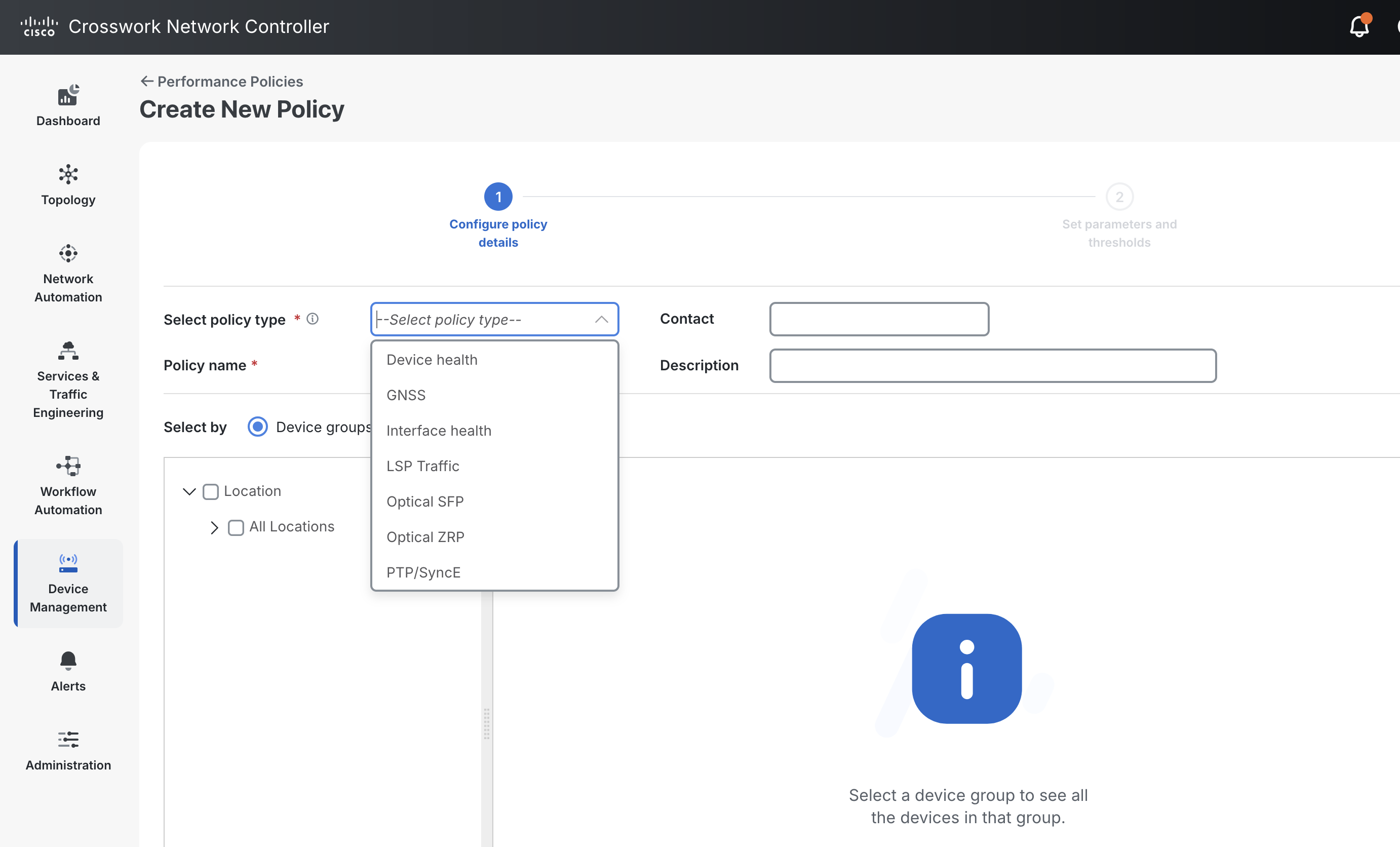
Once a policy is enabled on a device, it can then be monitored by looking at the inventory of the device.
Zero Touch Provisioning
In addition to model-driven configuration and operation, Agile Metro supports ZTP operation for automated device provisioning. ZTP is useful both in production as well as staging environments to automate initial device software installation, deploy an initial bootstrap configuration, as well as advanced functionality triggered by ZTP scripts. ZTP is supported on both out of band management interfaces as well as in-band data interfaces. When a device first boots, the IOS-XR ZTP process beging on the management interface of the device and if no response is received, or the the interface is not active, the ZTP process will begin the process on data ports. IOS-XR can be part of an ecosystem of automated device and service provisioning via Crosswork Network Controller and Cisco NSO.

Zero Touch Provisioning using Crosswork Network Controller
Crosswork Network Controller now includes a ZTP application used to onboard network devices with the proper IOS-XR software and base configuration. Crosswork ZTP supports both traditional unsecure as well as fully secure ZTP operation as outlined in RFC 8572. More information on Crosswork ZTP can be found at https://www.cisco.com/c/en/us/products/collateral/cloud-systems-management/crosswork-network-automation/datasheet-c78-743677.html
Underlay transport management using Crosswork Network Controller
Crosswork Network Controller provides support for provisioning SR-MPLS, SRv6, and RSVP-TE
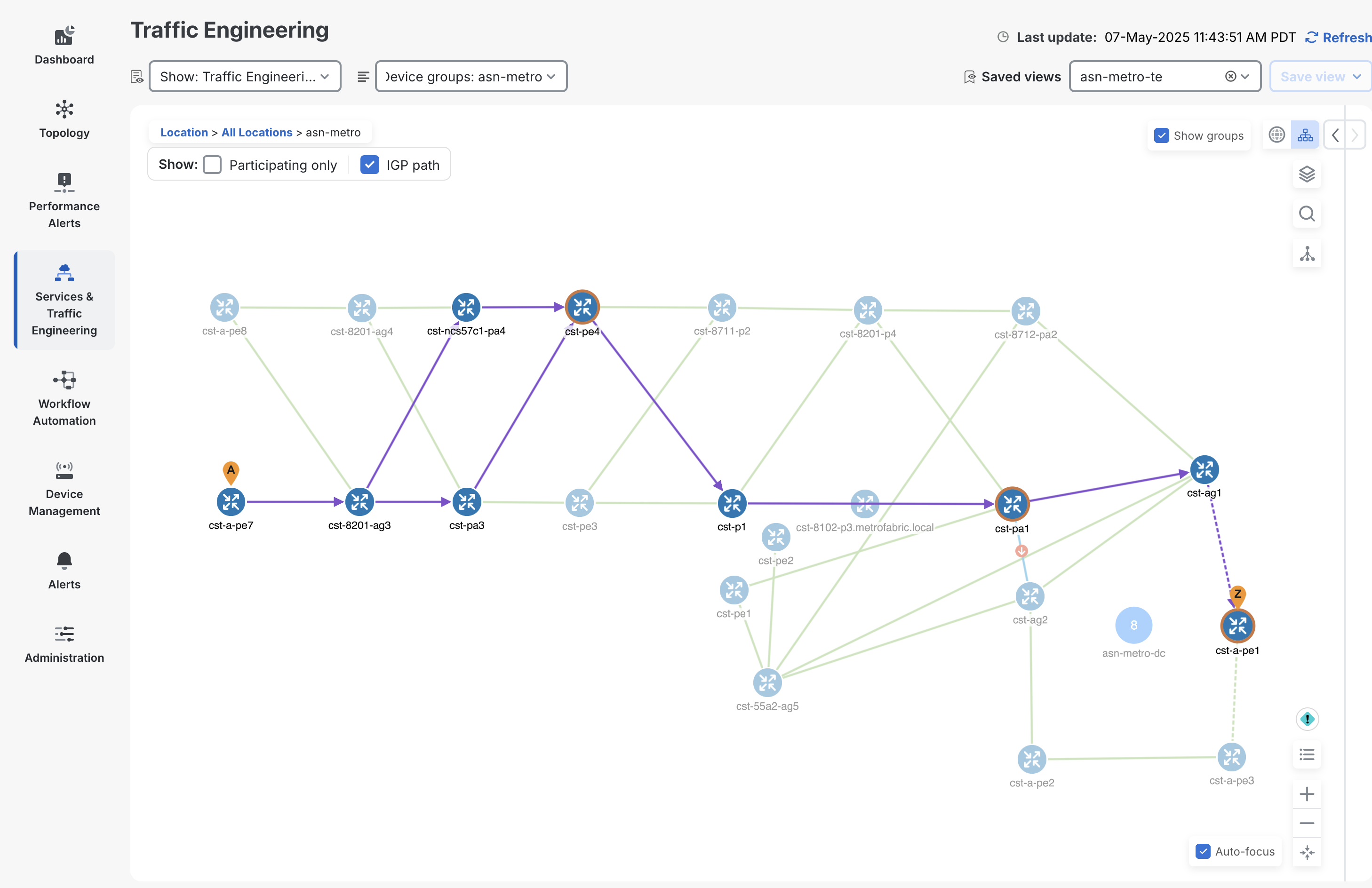
traffic engineering paths. The creation of the paths is done through standardized models where possible such as the IETF-TE RSVP-TE model. CNC supports full visualization of these paths across distributed multi-IGP instance networks. The following figure highlights the ability to visualize an end to end SRv6-TE path across multiple IS-IS instances.
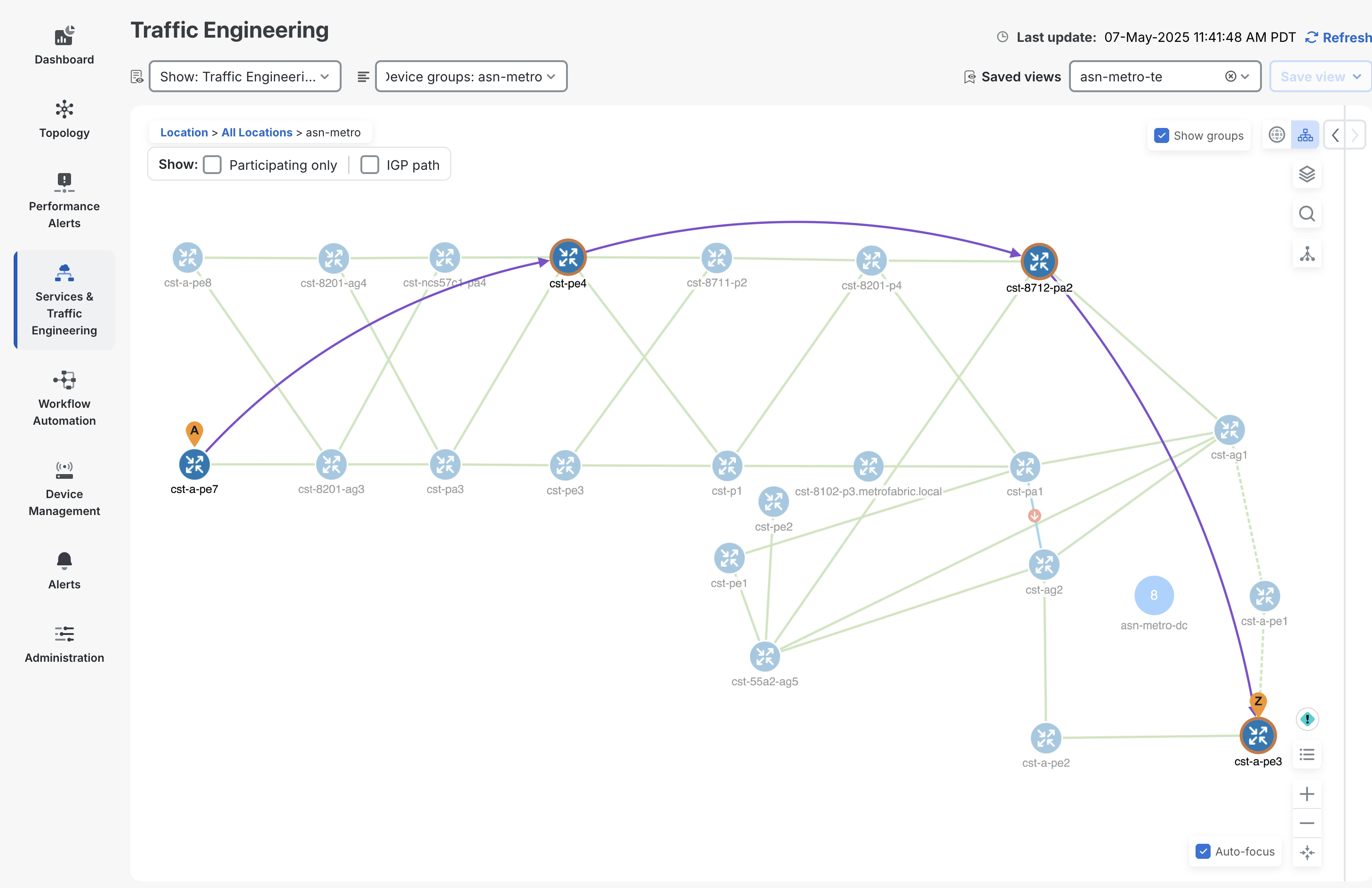
CNC can also visualize the end to end IGP path taken by each segment, showing ECMP traffic paths.
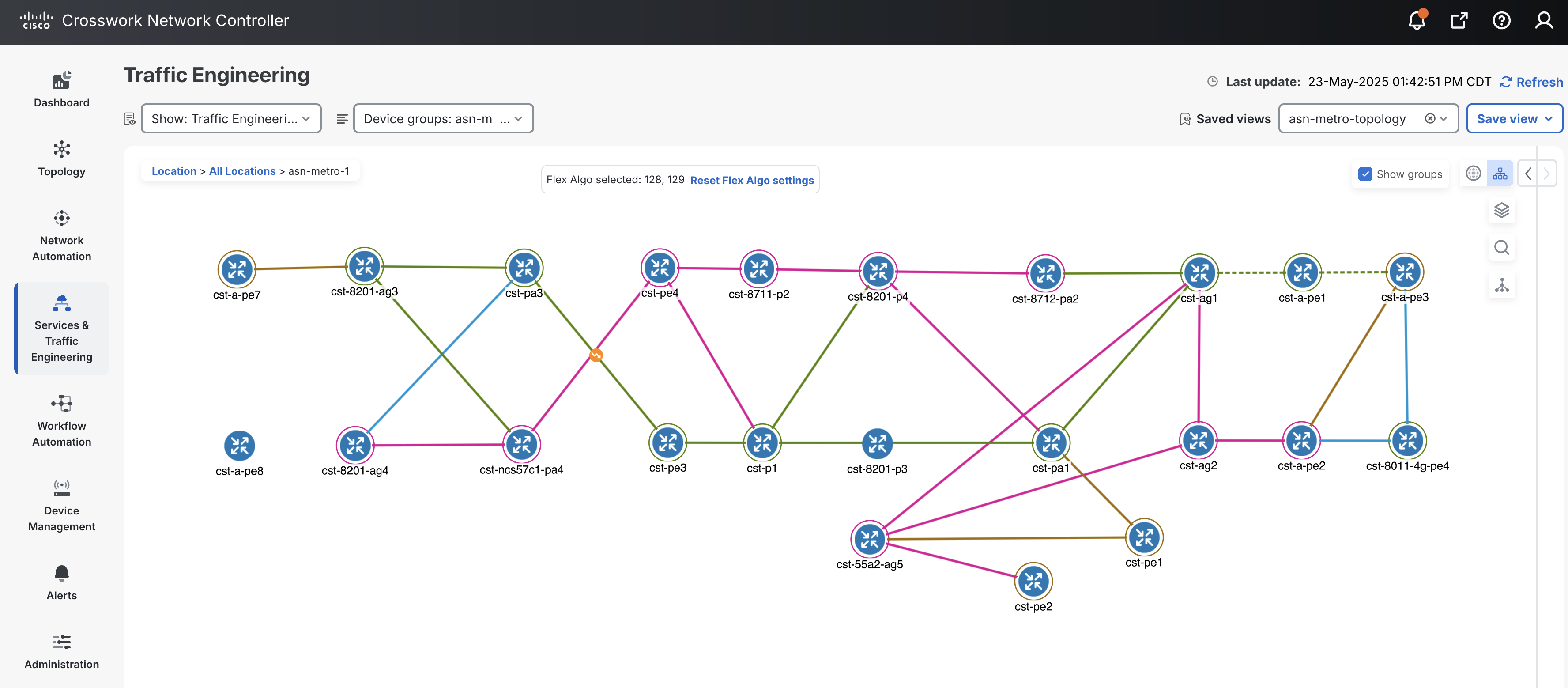
CNC also supports visualization of Segment Routing Flexible Algorithms deployed across the provider network. The following shows nodes participating in the 128 (pink) and 129 (green) algorithms along with links interconnecting nodes using the same algorithm. It also displays nodes participaing in both algorithms highlighted by the brown color.
Multi-Layer network management using Crosswork Hierarchical Controller
Crosswork Hierarchical Controller helps providers manage multi-layer IP+Optical transport networks. HCO’s powerful layered network model allows operators to combine service and infrastructure layers together to visualize and correlate faults. Fiber layer data can even be imported into HCO in order to trace service paths and faults to the fiber layer.
Crosswork HCO is a multi-vendor tool, communicating with IP and optical controllers to gather and combine multi-layer data. In Agile Metro 1.1 HCO does not communicate directly with devices, enhancing scalability and simplifying the overall deployment of the solution. All IP network layer data is learned from Crosswork CNC.
Routed Optical Networking multi-layer provisioning
Crosswork HCO is also responsible for multilayer provisioning of Routed Optical Networking circuits. These circuits originate on pluggable 100G or 400G DCO in the routers. Crosswork HCO can provision the following circuit use cases:
Base protocols supporting advanced use cases
Overview
The Agile Metro Design aims to enable simplification across all layers of a Service Provider network. Thus, the Agile Metro services layer focuses on a converged Services Control Plane based on BGP.
BGP based Services include L2VPN using EVPN and traditional L3VPN (VPNv4/VPNv6).
EVPN is a technology initially designed for Ethernet multipoint services to provide advanced multi-homing capabilities. EVPN uses BGP to distribute MAC address reachability information over the transport network, bringing the same operational and scale characteristics of IP based L3VPNs to L2VPNs. Today, beyond DCI and E-LAN applications, the EVPN solution family provides a common foundation for all Ethernet service types; including E-LINE, E-TREE, as well as data center routing and bridging scenarios. EVPN is also used to transport TDM services in Cisco’s Private Line Emulation solution. EVPN also provides options to combine L2 and L3 services into the same instance.
To simplify service deployment, provisioning of services is automated using Cisco Crosswork Network Controller and Cisco Network Services Orchestrator (NSO) using standard YANG data models where possible.
There are two types of services: End-To-End and Hierarchical. The next two sections describe these two types of services in more detail.
Ethernet VPN (EVPN)
EVPNs solve two long standing limitations for Ethernet Services in Service Provider Networks:
Multi-Homed & All-Active Ethernet Access
End to end integration across data centers and across network boundaries
Ethernet VPN Hardware Support
In Agile Metro EVPN VPWS services are supported on all IOS-XR devices. EVPN ELAN and ETREE services are supported on specific devices, please see specific router software roadmaps for support on all EVPN related features.
End-To-End Distributed (Flat) services
In Cisco’s Agile Metro design advanced services may have endpoints at any place in the network. The Cisco IOS-XR devices used in Agile Metro support point-to-point and multipoint unicast services and multipoint multicast services. Distributed service termination simplifies deployments by minimizing service stitching. Service stitching adds additional provisioning endpoints and adds complex control-plane and data-plane functions to provide redundancy.
The End-To-End Services use cases are summarized in the table in Figure 24 and shown in the network diagram in Figure 25.

Figure 24: End-To-End – Services table

Figure 25: End-To-End – Services
All services use cases are based on BGP Control Plane.
Refer also to Section: “Transport and Services Integration”.
Hierarchical Services
Hierarchical deployments may be used in scenarios where the service provider access equipment cannot support advanced multipoint L2/L3 service termination. In these networks a simple L2VPN pseudowire is used from the access node to a centralized PE device, where the L2VPN pseudowire is stitched into a multipoint L2VPN or L3VPN service.
Hierarchical Services Use Cases are summarized in the table of Figure 26 and shown in the network diagram of Figure 27.

Figure 26: Supported Hierarchical Services

Figure 27: Hierarchical Services Control Plane
Figure 27 shows hierarchical services deployed on PE routers, but the same design applies when services are deployed on AG or DCI routers.
The Agile Metro Design offers scalable hierarchical services with simplified provisioning. The three most important use cases are described in the following sections:
Hierarchical L2 Multipoint Multi-Homed/All-Active
Hierarchical L2/L3 Multi/Single-Home, All/Single-Active Service (H-EVPN) and Anycast-IRB
Hierarchical L2/L3 Multipoint Multi-Homed/Single-Active (H-EVPN) and PWHE
Hierarchical L2 Multipoint Multi-Homed/All-Active
Figure 28 shows a very elegant way to take advantage of the benefits of Segment-Routing Anycast-SID and EVPN. This use case provides Hierarchical L2 Multipoint Multi-Homed/All-Active (Single-Homed Ethernet access) service with traditional access router integration.

Figure 28: Hierarchical Services (Anycast-PW)
Access Router A1 establishes a Single-Active static pseudowire (Anycast-Static-PW) to the Anycast IP address of PE1/PE2. PEs anycast IP address is represented by Anycast-SID.
Access Router A1 doesn’t need to establish active/backup PWs as in a traditional H-VPLS design and doesn’t need any enhancement on top of the established spoke pseudowire design.
PE1 and PE2 use BGP EVPN Control Plane to provide Multi-Homed/All-Active access, protecting from L2 loop, and providing efficient per-flow load-balancing (with aliasing) toward the remote PEs (PE3/PE4).
A3, PE3 and PE4 do the same, respectively.
Hierarchical L2/L3 Multi/Single-Home, All/Single-Active Service (H-EVPN) and Anycast-IRB
Figure 29 shows how EVPNs can completely replace the traditional H-VPLS solution. This use case provides the greatest flexibility as Hierarchical L2 Multi/Single-Home, All/Single-Active modes are available at each layer of the service hierarchy.

Figure 29: Hierarchical Services (H-EVPN)
Optionally, Anycast-IRB can be used to enable Hierarchical L2/L3 Multi/Single-Home, All/Single-Active service and to provide optimal L3 routing.
Hierarchical L2/L3 Multipoint Multi-Homed/Single-Active (H-EVPN) and PWHE
Figure 30 shows how the previous H-EVPN can be extended by taking advantage of Pseudowire Headend (PWHE). PWHE with the combination of Multi-Homed, Single-Active EVPN provides an Hierarchical L2/L3 Multi-Homed/Single-Active (H-EVPN) solution that supports QoS.
It completely replaces traditional H-VPLS based solutions. This use case provides Hierarchical L2 Multi/Single-Home, All/Single-Active service.

Figure 30: Hierarchical Services (H-EVPN and PWHE)
EVPN Centralized Gateway
Similar to the Hierarchical L2/L3 service with Anycast-IRB, EVPN Centralized Gateway extends that service type by allowing the use of EVPN-ELAN services between the access site and core location. In previous versions the Anycast-IRB L3 gateway needed to be part of the access L2 domain and could not be placed elsewhere in the EVPN across the core network. EVPN CGW relaxes the constraint and allows the L3 Anycast IRB gateway to be located at any point in the EVPN ELAN. The IRB can be placed in either the global routing table or within a VRF.
In Agile Metro EVPN Centralized GW is supported on the ASR 9000 platform.
The figure below shows an example EVPN CGW deployment. In this scenario A-PE3, A-PE4, A-PE5, PE1, and PE2 all belong to the same EVPN-ELAN EVI 100. The CE nodes connected to A-PE3, A-PE4, and A-PE5 can communicate at Layer 2 or Layer 3 with eachother without having to traverse the core nodes. This is one fundamental difference between EVPN-CGW and EVPN-HE. Traffic destined to another subnet, such as the 10.0.0.2 address is routed through the CGW core gateway.
Also in this example CE4 is an example of a multi-homed CE node, utilizing a LAG across A-PE4/A-PE3. This multi-homed connection can be configured in an all-active, single-active, or port-active configuration.

Figure 31: Hierarchical Services EVPN Centralized GW
EVPN Head-End for L3 Services
Agile Metro also supports Cisco’s EVPN Head-End solution for hierarchical services. EVPN Head-End is similar to the existing Hierarchical PWHE services, but allows the use of native EVPN-VPWS between the access PE node and centralized PE node. This simplifies deployments by allowing providers to use the fully dynamic EVPN control plane for signaling, including the ability to signal active/backup signaling between access PE and core PE nodes. In CST 5.0 EVPN-HE is supported for L3 service termination, with the L3 gateway residing on either a PWHE P2P interface or BVI interface. The L3 GW can reside in the global routing table or within a VRF.
In Agile Metro EVPN-HE for L3 services is supported on the ASR 9000 platform and select P100 line cards such as the 88-LC1-12TH24FH-E and 88-LC1-52Y8H-EM.
The figure below shows a typical EVPN Head-End deployment. A-PE3 is configured as an EVPN-VPWS endpoint, with PE1 and PE2 configured with the same EVPN-VPWS EVI, acting as All-Active or Single-Active gateways. PE1 and PE2 are configured with the same 10.1.0.1/24 address on the terminating L3 interface, providing a redundant gateway for the CE device with address 10.1.0.2/24. While not shown in this figure, the CE device could also be multi-homed to two separate A-PE nodes in a all-active, single-active, or port-active configuration.

Leave a Comment