
Implementing Layer2 VPN Over SRv6 Transport on NCS 5500/500
| Paban Sarma, Technical Marketing Engineer ([email protected]) |
| Tejas Lad, Technical Marketing Engineer ([email protected]) |
Overview
Until now we covered setting up, SRv6 Transport and bringing up Layer3 VPN using that on NCS 5500 and NCS 500 platforms. In this tutorial, we will cover the impelementaion of EVPN based point-to-point (E-Line) L2 service (EVPN-VPWS) over SRv6.
Topology
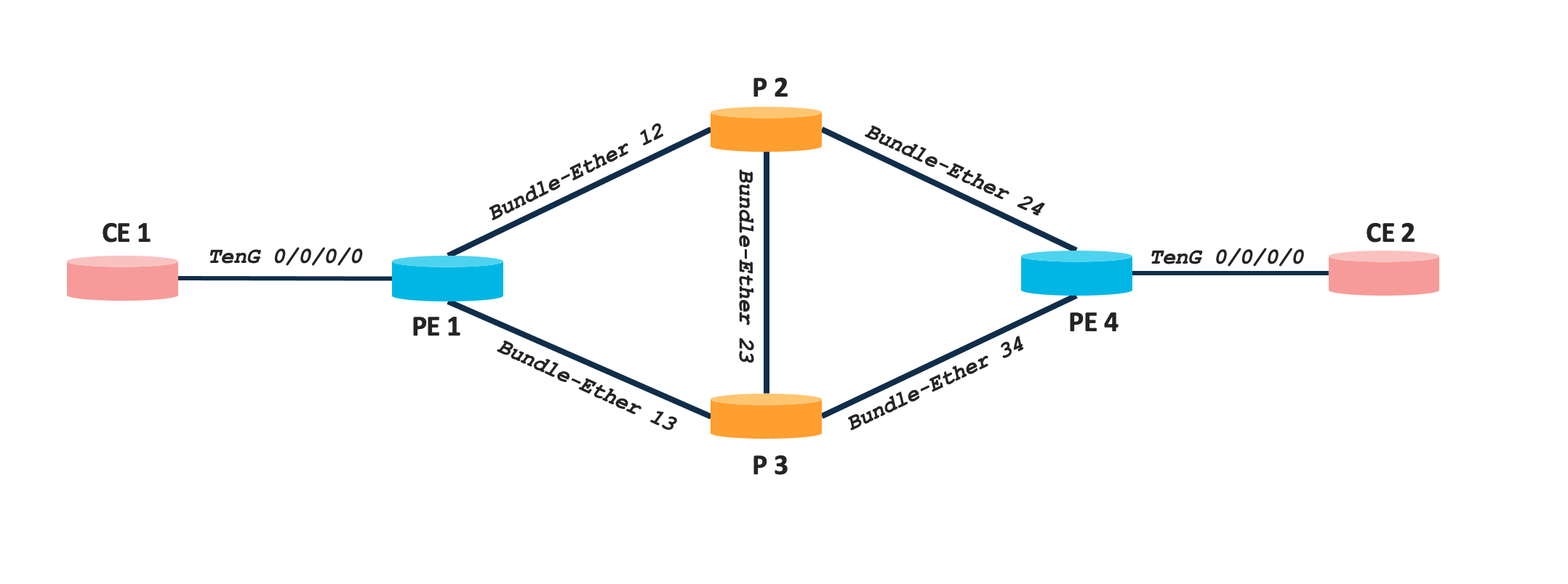
The topology used is a simple four node network comprising of Cisco NCS 540 and NCS 5500 series platforms. There are two CE nodes connected to PE1 and PE4 respectively to simulate customer networks. Details of each node along with Loopback IPs are mentioned in the below table.
| Nodes | Device Type | Software Version | Loopback0 |
|---|---|---|---|
| PE1 | NCS 540 | IOS XR 7.5.2 | fcbb:bb00:1::1/128 |
| P2 | NCS 5500 | IOS XR 7.5.2 | fcbb:bb00:2::1/128 |
| P3 | NCS 5500 | IOS XR 7.5.2 | fcbb:bb00:3::1/128 |
| PE4 | NCS 5500 | IOS XR 7.5.2 | fcbb:bb00:4::1/128 |
The loopback0 IPs are chosen as per the SRv6 addressing best practice (check out segment-routing.net for more details).
In this tutorial, we will establish a L2VPN (EVPN-VPWS) connecting CE1 and CE2. the example will demonstrate VLAN based E-Line (EVPL) service and establish L2 stretch across CE1 and CE2 for VLAN 100.
Configuration Steps
EVPN based P2P service over SRv6 transport will involve 3 steps, viz.
- Establishing EVPN control plane over BGP
- Configuring l2transport between CE-PE links
- Configuring EVPN EVI and L2VPN Service
BGP Control Plane
Traditional L2 services uses LDP for signalling, which is simplified by EVPN with the use of BGP for control plane operation. In our previous tutorial, we established BGP neighborship between PE1 and PE4 with VPNv4 AFI. Now we need to enable EVPN AFI over BGP. Below snippet shows full BGP configuration needed for layer2 service over SRv6.
PE1
router bgp 100
 bgp router-id 1.1.1.1
 address-family l2vpn evpn
 !
 neighbor fcbb:bb00:4::1
  remote-as 100
  update-source Loopback0
  address-family l2vpn evpn
  !
 !
!
PE4
router bgp 100
 bgp router-id 4.4.4.4
 address-family l2vpn evpn
 !
 neighbor fcbb:bb00:1::1
  remote-as 100
  update-source Loopback0
 address-family l2vpn evpn
  !
 !
!
Configuring Layer2 Attachment Circuits
We need to configure l2transport sub-interface (on the PE-CE link) with appropriate VLAN encapsulations. This tutorial is showing VLAN based service with VLAN ID 100. We are not showing any VLAN translation operation (rewrite commands) as the are out of scope of this tutorial.
PE1 and PE4
interface TenGigE0/0/0/0.2 l2transport
 encapsulation dot1q 2
Configuring EVPN and L2VPN Service
Next step is to configure EVPN and L2VPN service construct on both the PE. since we have a symmetric topology, our configuration on both node will be similar. Configure the below on PE1 and PE4.
evpn
 interface TenGigE0/0/0/0
 !
 segment-routing srv6
  locator POD0
 !
!
l2vpn
 xconnect group 2
  p2p 2
   interface TenGigE0/0/0/0.2
   neighbor evpn evi 2 service 2 segment-routing srv6
   !
  !
 !
!
The interface under EVPN configuration doesn’t have any ESI configured, this is because of single homed service and default ESI being used. For detailed understanding on evpn configuration and modes refer e-evpn.io. We have globally enabled srv6 locator POD0 under evpn, this means l2vpn SIDs (UDX2) will be allocated from the same locator. The srv6 configuration under l2vpn xconnect group service construct can be used to override the global evpn configuration and assign new locator.
Verifiation Steps
At first we will verify that the layer2 P2P service is up,
RP/0/RP0/CPU0:LABSP-3393-PE1#show l2vpn xconnect
Legend: ST = State, UP = Up, DN = Down, AD = Admin Down, UR = Unresolved,
        SB = Standby, SR = Standby Ready, (PP) = Partially Programmed,
        LU = Local Up, RU = Remote Up, CO = Connected, (SI) = Seamless Inactive

XConnect                   Segment 1                       Segment 2
Group      Name       ST   Description            ST       Description            ST
------------------------   -----------------------------   -----------------------------
2          2          UP   Te0/0/0/0.2            UP       EVPN 2,2,::ffff:10.0.0.2
                                                                                  UP
----------------------------------------------------------------------------------------
The local SID information for the configured service is updated in the SRv6 SID table as well.
RP/0/RP0/CPU0:LABSP-3393-PE1#show  segment-routing srv6  locator POD0 sid
SID                         Behavior          Context                           Owner               State  RW
--------------------------  ----------------  ------------------------------    ------------------  -----  --
fcbb:bb00:1::               uN (PSP/USD)      'default':1                       sidmgr              InUse  Y
fcbb:bb00:1:e001::          uA (PSP/USD)      [BE12, Link-Local]:0:P            isis-1              InUse  Y
fcbb:bb00:1:e002::          uA (PSP/USD)      [BE12, Link-Local]:0              isis-1              InUse  Y
fcbb:bb00:1:e003::          uA (PSP/USD)      [BE13, Link-Local]:0:P            isis-1              InUse  Y
fcbb:bb00:1:e004::          uA (PSP/USD)      [BE13, Link-Local]:0              isis-1              InUse  Y
fcbb:bb00:1:e005::          uDT4              '1'                               bgp-100             InUse  Y
fcbb:bb00:1:e006::          uDX2              2:2                               l2vpn_srv6          InUse  Y
The SID details and functions can also be verified using SID details CLI as shown below. It shows that the SID function is 0xe0006 and it is in the context of EVPN EVI 2 with AC IDs 2 (eth-tag=2).
RP/0/RP0/CPU0:LABSP-3393-PE1#show  segment-routing srv6 sid fcbb:bb00:1:e006::  detail


*** Locator: 'POD0' ***

SID                         Behavior          Context                           Owner               State  RW
--------------------------  ----------------  ------------------------------    ------------------  -----  --
fcbb:bb00:1:e006::          uDX2              2:2                               l2vpn_srv6          InUse  Y
  SID Function: 0xe006
  SID context: { evi=2, eth-tag=2 }
  Locator: 'POD0'
  Allocation type: Dynamic
  Created: Nov 14 04:49:43.505 (00:08:54 ago)
We can also view, the SRv6 uDX2 SID assigned to each segment of the service in the detailed show command below:
RP/0/RP0/CPU0:LABSP-3393-PE1#show  l2vpn xconnect group 2 detail

Group 2, XC 2, state is up; Interworking none
  AC: TenGigE0/0/0/0.2, state is up
    Type VLAN; Num Ranges: 1
    Rewrite Tags: []
    VLAN ranges: [2, 2]
    MTU 1504; XC ID 0x2; interworking none
    Statistics:
      packets: received 0, sent 0
      bytes: received 0, sent 0
      drops: illegal VLAN 0, illegal length 0
  EVPN: neighbor ::ffff:10.0.0.2, PW ID: evi 2, ac-id 2, state is up ( established )
    XC ID 0xc0000002
    Encapsulation SRv6
    Encap type Ethernet
    Ignore MTU mismatch: Enabled
    Transmit MTU zero: Enabled
    Reachability: Up

      SRv6              Local                        Remote
      ----------------  ---------------------------- --------------------------
       uDX2              fcbb:bb00:1:e006::           fcbb:bb00:4:e006::
      AC ID             2                            2
      MTU               1518                         0
      Locator           POD0                         N/A
      Locator Resolved  Yes                          N/A
      SRv6 Headend      H.Encaps.L2.Red              N/A
    Statistics:
      packets: received 0, sent 0
      bytes: received 0, sent 0
We can verify the Remote uSID advertised via BGP with the help of the below CLI outputs.
RP/0/RP0/CPU0:PE1#show  bgp  l2vpn evpn
BGP router identifier 1.1.1.1, local AS number 100
BGP generic scan interval 60 secs
Non-stop routing is enabled
BGP table state: Active
Table ID: 0x0
BGP main routing table version 20
BGP NSR Initial initsync version 1 (Reached)
BGP NSR/ISSU Sync-Group versions 0/0
BGP scan interval 60 secs

Status codes: s suppressed, d damped, h history, * valid, > best
              i - internal, r RIB-failure, S stale, N Nexthop-discard
Origin codes: i - IGP, e - EGP, ? - incomplete
   Network            Next Hop            Metric LocPrf Weight Path
Route Distinguisher: 1.1.1.1:2 (default for vrf VPWS:2)
*> [1][0000.0000.0000.0000.0000][2]/120
                      0.0.0.0                                0 i
* i                   fcbb:bb00:4::1                100      0 i
Route Distinguisher: 4.4.4.4:2
*>i[1][0000.0000.0000.0000.0000][2]/120
                      fcbb:bb00:4::1                100      0 i

Processed 2 prefixes, 3 paths

RP/0/RP0/CPU0:LABSP-3393-PE1#show  bgp  l2vpn evpn rd 4.4.4.4:2 [1][0000.0000.0000.0000.0000][2]/120
BGP routing table entry for [1][0000.0000.0000.0000.0000][2]/120, Route Distinguisher: 4.4.4.4:2
Versions:
  Process           bRIB/RIB  SendTblVer
  Speaker                  19           19
Last Modified: Nov 14 04:50:18.448 for 2d00h
Paths: (1 available, best #1)
  Not advertised to any peer
  Path #1: Received by speaker 0
  Not advertised to any peer
  Local
    fcbb:bb00:4::1 (metric 30) from fcbb:bb00:4::1 (4.4.4.4)
      Received Label 0xe00600
      Origin IGP, localpref 100, valid, internal, best, group-best, import-candidate, not-in-vrf
      Received Path ID 0, Local Path ID 1, version 19
      Extended community: EVPN L2 ATTRS:0x02:0 RT:100:2
      PSID-Type:L2, SubTLV Count:1
       SubTLV:
        T:1(Sid information), Sid:fcbb:bb00:4::, Behavior:65, SS-TLV Count:1
         SubSubTLV:
          T:1(Sid structure):
There is single RT1 coming from PE4 with all zero ESI as we have only used single-homing. A detailed look into the advertised route shows that the remote uDX2 sid comprise of the two parts, the Sid information fcbb:bb00:4:: with Behavior:65 meaning this is uDX2. Also the received label is 0xe00600 . Thus, we can see that the remote uDX2 SID fcbb:bb00:4:e006:: comprises of SID and the Received_Label.
Finally, to verify the data plane operation we will initiate ICMP ping from CE1 to CE2. we already have configured CE1 & CE2 in the same subnet and established the L2 stretch between the two nodes with EVPN-VPWS over SRv6 transort.
RP/0/RP0/CPU0:CE1#show run int tenGigE 0/0/0/0.2
interface TenGigE0/0/0/0.2
 ipv4 address 192.2.0.1 255.255.255.0
 encapsulation dot1q 2
!

RP/0/RP0/CPU0:CE2#show run int tenGigE 0/0/0/0.2
interface TenGigE0/0/0/0.2
 ipv4 address 192.2.0.2 255.255.255.0
 encapsulation dot1q 2
!

RP/0/RP0/CPU0:CE1#ping 192.2.0.2 repeat 20
Type escape sequence to abort.
Sending 20, 100-byte ICMP Echos to 192.2.0.2, timeout is 2 seconds:
!!!!!!!!!!!!!!!!!!!!
Success rate is 100 percent (20/20), round-trip min/avg/max = 1/3/45 ms
RP/0/RP0/CPU0:CE1#
Conclusion
This concludes Part 3 of our tutorial explaing point-to-point l2 serviec over SRv6 transport. Stay tuned for our upcoming tutorials.
Leave a Comment