
Inside IOS XR - Part 1
Introduction
This blog is the first in a series about IOS XR’s software architecture. I believe that many of today’s best-practice architecture/design patterns for a successful buildout of scalable network system are rooted in the IOS XR’s architecture.
In this series, I will explore the part of IOS XR that is typically invisible, and describe IOS XR’s architecture from its foundations up. I go into why the architecture looks like it does, introduce key architecture patterns, and draw occasional parallels with other scalable and high-performance software.
IOS XR Evolution
When IOS XR started its journey several years ago, Google, Facebook, AWS, etc. were not around. The world had not yet begun to massively scale!
Many of the massively scalable distributed system patterns that are perhaps more familiar to software developers these days were not that popular yet (mostly limited to textbooks or were part of a few closed commercial software implementations).
There weren’t yet messaging infrastructures like ActiveMQ, RabbitMQ, ZeroMQ, Nanomsg, Kafka, etc., in-memory databases like Redis, Memcached, Hazelcast, etc., or distributed file systems (DFS) like HDFS, GlusterFS, CEPH, etc.
Around this time, Cisco had embarked on building the next generation Network Operating System (NOS) with one clear vision: building a highly scalable, reliable, available, modifiable, high performance NOS for the Service Provider (SP) space that caters all the way from low end single chassis systems to massive high end multi-chassis routers. Pulling this off required leveraging the deep networking knowledge base from the Cisco IOS operating system. In addition, to meet the rigorous SP requirements for this NOS, a slew of ground breaking infrastructure and distributed systems architecture patterns were brought into the system. The following picture shows the high level requirements of IOS XR and the resulting architecture patterns that were built into the software:
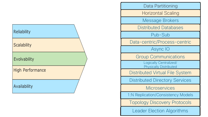
Picture 1: Requirements and Resultant Architecture Patterns
Before we get into the details of the above IOS XR architecture patterns in detail in the rest of the blog, it is worth quickly going through a summary of how the IOS XR has evolved over the years. There are several dimensions across which the IOS XR has demonstrated its modularity and adaptability capabilities, with some major evolutions over the years. The following table summarizes these evolutions:
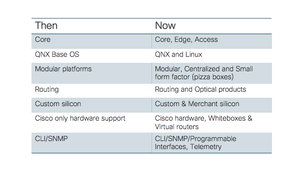
Each of the above is a significant evolution and demonstrates IOS XR’s ability to evolve and take on new challenges ✅
The IOS XR Architecture Strategy
So how does one architect a carrier grade NOS?
The Cisco IOS XR Network Operating System (NOS) is developed not by changing the solution to an existing problem, but rather asking a different question by looking at the customer’s networking needs for decades to come. The high level and heavily simplified IOS XR architecture strategy can be explained via the following six steps:
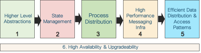
Picture 2: IOS XR Architecture Strategy
- Appropriate higher level abstractions capture the essence of the system and they are key in driving the subsequent architecture/design patterns.
- Once abstractions are in place, IOS XR has focused on large state management in a router. (State is simply the condition or quality of an entity at an instant in time, and it is usually represented by data in the system; hence, state and data are used interchangeably in this blog).
- Once the state generation and distribution patterns are modeled correctly, the next step is the design and placement of the processes that work with this state.
- But processes in a router interact with each other within a node (intra-node) and across the nodes (inter-node), often times moving a significant amount of data with specific latency requirements. Hence the next important logical step in the architecture is designing a high-performance messaging infrastructure.
- The final step, once the messaging infrastructure is in place, is to understand different data access and distribution patterns of various applications over the messaging infrastructure and design those constructs.
- The high availability and upgradeability considerations span across all the stages.
In the rest of the blog, we dig into the internals of each of these IOS XR architecture strategy steps, and discuss principles and trade-offs in each step. On this journey, we will try to find useful ways of thinking about IOS XR NOS — not just how it is architected, but also why it is architected that way, and what to look for in a good NOS in general.
Higher Level Abstractions: Decoupled Planes
IOS XR is a multi-process, distributed network operating system with tall order goals as mentioned earlier. In order to deliver on those goals, strong architectural abstractions are necessary. The IOS XR is architecturally divided into the following three planes:
- Management plane
- Control plane
- Data plane
These planes are a categorization of the traffic handled by a router and they provide an abstraction for the architecture of the router software. The planes abstraction helps in hiding a great deal of implementation detail behind a clean and nice facade. The management plane implements the external user interface used by operators to configure and query the system. The control plane is responsible for determining routes to use for traffic flows and generally how traffic should be forwarded. The control plane protocols (e.g. routing protocols) exchange information with other devices. The data plane directs traffic flows through the device. Forwarding is typically performed by hardware (but can be software) and data plane software is responsible for setting up hardware to perform forwarding.
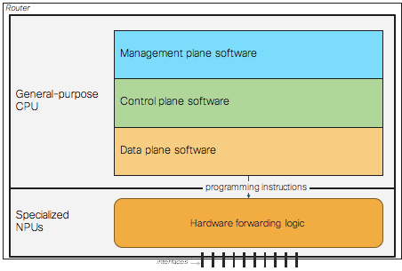
Picture 3: Decoupled IOS XR Planes
While the above three planes are perhaps more well known, there is a relatively less visible Infrastructure Plane behind the three planes, providing various key architecture/design patterns that are the subject of the rest of this blog.
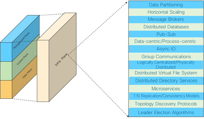
Picture 4: The Invisible Infra Plane Supoorting The Architecture Patterns
State Management
A NOS in a router produces a lot of state. This router state is created by external inputs (sourced state) as well as internal code flow (generated state).
Some examples of this state/data are configuration data, routing data, interfaces data, high-availability data, feature data (ACL, QoS, etc.), statistics, protocol data, environmental data, platform data, operational data, etc. This data, depending on its type, has different access patterns (most data is accessed only by a few entities in the cluster, and there is a very limited set of data that is accessed very broadly), frequency patterns (a few data items that are going to be very frequently accessed and the vast majority that will be rarely accessed), data set sizes (large routing tables, huge operational data, small configuration, etc.) and so on. This influences the data partitioning/placing as well as data distribution and access mechanisms by different entities in the router cluster (discussed a bit later in this blog).
In order to make the overall system scalable and highly available, the following architecture patterns are built into the IOS XR after taking into account the state/data attributes mentioned above:
- Distributed state partitioning
- Shared state concurrency
- Caching mechanisms
- State replication and consistency mechanisms
- Use space resident IOS XR state
- Microservices
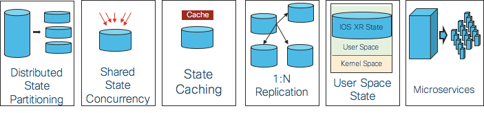
Picture 5: State Management Architecture Patterns
Distributed state partitioning
The state is partitioned and available across the available compute nodes (route processors, line card processors, external compute processors, etc., across the route cluster) as follows:
- Sourced state is partitioned across available compute as required.
- Generated state is kept on the source node as much as possible.
- Data is distributed in such a way as to minimize communication among nodes.
For example, system databases specific to the line card, such as interface-related configurations, interface states, and so on, are stored on the line card. Run-time configuration flows to the node (route processor, line card, etc.) where it is applicable.
The different IOS XR nodes run independently, and the data partitioning also helps with fault tolerance/high-availability and low latency.
Shared state concurrency
When two or more processes have some shared state between them, IOS XR is designed for concurrent data access by multiple clients. For example, configuration and operational data can be accessed by multiple internal/external clients simultaneously.
Caching mechanisms
Carefully designed state caching mechanisms at appropriate nodes in the cluster exist in the system.
State replication and consistency mechanisms
Replication is the process of synchronizing several copies of the same state located at different nodes in a router cluster and is used to increase the availability of data and to speed up query evaluation. This is a fundamental requirement for IOS XR and provides a generic replication and consistency management scheme for multiple copies of an opaque data set. It supports and scales well for multi-chassis systems providing an asynchronous 1:N replication method that spans one or more chassis.
IOS XR also studied various consistency models in the context of the distributed router cluster and designed its infrastructure so that applications can choose the required consistency model based on their needs. This is akin to Amazon’s Dynamo providing various consistency models and letting the application choose the required consistency model while taking into account its availability, performance, etc. metrics.
IOS XR also provides a distributed virtual file system built on top of its replication framework. The motivation for this distributed file system lies in the high availability requirements of IOS XR router clusters. Nodes can go down and come back online at any time. Applications on these nodes need to access files in a location-independent manner. Designating special nodes as file servers means the entire system is affected if the special nodes go down. This infrastructure is designed as decentralized, as all replicas are designed as connectionless, anonymous peers.
User space resident IOS XR state
This dimension deals with distribution of state within a node between user and kernel spaces. Since IOS XR has started its journey with QNX micro kernel, the IOS XR’s state resides completely outside the kernel. IOS XR has maintained this pattern, as it moved from QNX to Linux as its base operating system.
This clean separation between user and kernel space enables several advantages like better stability of the system; a lot more freedom to bring in, modify, and optimize user space code; and increased modularity and independent upgradeability of kernel/user space code modules. For example, the IOS XR TCP/IP stack is completely home grown and resides in the user space. It is designed while keeping high end NOS in mind with a lot of optimizations/features. This stack plays a key role in IOS XR BGP and various other protocols/features’ high performance numbers.
Microservices
Microservice is a hot buzzword in the industry today. There is no golden rule for the architecture in microservices. If we go by different architectures implemented in the industry, we can see that everybody has their own flavor of microservice architecture. There is no perfect or certain definition of microservice. Rather microservices architecture can be summarized by certain characteristics or principles. Of course, when IOS XR was designed, there was no microservices buzzword, but since the IOS XR focused on modularity, loose coupling, high availability, etc., many of the microservice characteristics are built into the IOS XR’s architecture. For example, the following table below captures key microservice characteristics and the IOS XR’s corresponding behavior against each item:
| Microservice Characteristics | IOS XR Characteristics |
|---|---|
| Any component/service’s failure should be in isolation. Failure of one service should not make the whole application go down. | The component isolation is provided via process abstraction. Processes support restartability and failure of a process doesn’t affect the overall router health. |
| Components should talk to each other via predefined protocols. | There are contracts among components and the communication is via a mutually agreed upon protocol. |
| Each component in the system should be cohesive, independent, and self-deployable. | Individual components are bundled and delivered to customer as “software packages”. Each package provides a feature(s) which can be installed, activated or upgraded/downgraded at runtime by customers. Packages can be installed/activated on all or subset of nodes by customer at runtime. Different version of software packages can be activated on different nodes. Backup copies kept on the box to rollback. |
| Each component or microservice should have its own database, with whom only that service is interacting. No other component or service can fetch or modify the data in that database. | Each component’s private data is in its own private memory space. It is not accessible to others. |
| Each component with a specific purpose. | The components are well defined modules implementing protocols, forwarding, drivers, features, specific infrastructure etc. |
| Expose functionality as a service. | Each component, by design, exposes a public API that is used by other components. |
| The system should have automated testing in place. | Many automated testing suites exist and more are being developed. |
| Two or more loosely coupled components | The smallest software building block is a component. A component can be a DLL or process. Each component has metadata which defines the characteristic of that component. |
Process Distribution Across Available Compute
For scalability, the router cluster processes’ load needs to be distributed across the available compute. The IOS XR uses two modes of distribution.
- Localization
- Load distribution
The first distribution model uses localization, which performs processing and storage closer to the resource. With this model, a database specific to a node is located on that node. The storage/data part is already addressed in the previous section. Similarly, processes are placed on a node where they have greater interaction with the resource. For example, Address Resolution Protocol (ARP), interface manager (IM), Bidirectional Failure Detection (BFD), adjacency manager, and Forwarding Information Base (FIB) manager are located on the line cards and are responsible only for managing resources and tables on that line card. This enables IOS XR to achieve faster processing and greater scalability.
The second distribution model uses load distribution, in which additional route processors (RPs) are added to the system and processes are distributed across different RPs. Routing protocols, management entities, and system processes are examples of processes that can be distributed using this model.
High Performance Messaging Infrastructure
So far, we talked about scalable data partitioning and intelligent process placement. The next key piece is the messaging infrastructure that lets these processes communicate inter-node and intra-node.
Messaging is at the core of many architectures including IOS XR and is a difficult problem. Connecting two pieces is fine, but connecting hundreds and thousands is a different ball game. If we look at a modular router chassis with 12,16,18, etc. slots and tens/hundreds of processes per slot, we can see that we are already looking at the problem of messaging among hundreds/thousands of end points. These numbers go up further in multi-chassis clusters. There are a variety of applications (routing protocols, RIBs, FIBs, ACL/QoS, etc., features, platform applications, interface managers, manageability agents, etc.) and their communication requirements vary drastically w.r.t. scale, reliability, performance, etc.
For example, the following picture shows several dimensions which have been analyzed extensively across various applications while developing and evolving the IOS XR’s messaging infrastructure and some resulting architecture patterns:
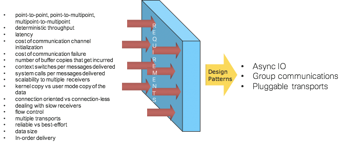
Picture 6: Messaging Infrastructure Architecture Patterns
The rest of this section looks at the following key design patterns that IOS XR has pioneered.
- Asynchronous IO
- Group communications
- Messaging protocols with pluggable transports
Asynchronous IO
Synchronous programming is arguably easier to reason about and implement. Synchronous communication requires that the sender and the receiver be coupled together during the message exchange. Since the receiver may not be ready to receive a message when it is sent, synchronous communication requires that the sender be blocked until the message is processed by the receiver, and it is some sort of acknowledgement or reply from the receiver that allows the sender to be unblocked. Thus, with synchronous IPC, the sender and receiver are essentially in lockstep for the duration of the message exchange.
With asynchronous communication the sender and receiver are uncoupled - the sender does not know when the receiver processed a message that was sent. The async communication results in better IPC throughput, less latency, and better use of allocated scheduler time slice, resulting in less thrashing of processes involved in IPC and better use of multi-core environment. Asynchronous IPC allows an application to function with a minimal number of threads.
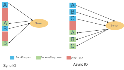
Picture 7: Synchronous and Asynchronous IO
We in IOS XR have realized very early on (circa 2000) that to make the system scalable, asynchronous communication is a key construct in the system. The IOS XR’s Group Communications, which is covered later, kicked off this journey right off the bat for the inter-node IO. Subsequently, due to extensive scalability analysis and experience gained during the CRS multi-chassis development, the Async IO became a key construct for a lot of intra-node communication as well. We found that applications which run with fewer threads have less effect on scheduler latencies, in general, and consequently are less of a burden on the overall system. With asynchronous IPC, the same sender’s thread can have multiple outstanding messages at a time––no need for a thread per message being sent, as is the case with synchronous IPC.
Hence IOS-XR is designed as a distributed system with loose coupling among various IOS XR instances across nodes. Different IOS XR nodes run independently; there are no master-slave relationships among the different cards running IOS XR code. The statement of loose coupling among the IOS XR nodes is further stated that the different instances of IOS XR can only learn of each other’s state and share data through asynchronous message passing. The asynchronous IO pattern is supported across point-to-point and point-to-multipoint connections.
One can see the Async IO being a key pattern for scalability these days. For example, when Node.js was launched (circa 2009), it became popular overnight. It was based on one strong fundamental that any time we make an out-of-process call, we should not be wasting the hardware resources and instead free up the thread to do other things. ZeroMQ, one of the successful messaging architectures launched around 2007, prides itself in its background Async IO module, how it uses lock-free algorithms for its queues, how it scales to any number of cores, how CPU quantum is efficiently utilized, etc.
Group communications
In a modular router, there are many applications that implicitly have a requirement to communicate in a group. Typically, these are processes on different nodes in a router that need to communicate to share data and/or to synchronize with each other. IOS XR is one of the first NOSs that has pioneered this Group Communications concept (depicted in the following picture) with the following characteristics:
- One-to-many reliable group communication
- Connectionless, asynchronous semantics
- Efficient resource/data location through reliable multicast
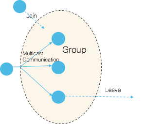
Picture 8: Group Communications
Because of these characteristics, IOS XR Group Services offers a very scalable communication method when multiple nodes are involved. Reliable, multicast, and asynchronous are the key words worth noting above. If we take the reliability away from the Group Communications, it is akin to the Pub-Sub pattern, where a message is directed at many subscribers and publishers, and subscribers are completely decoupled.
Pub-sub is aimed at scalability, where the publisher pushes data without really worrying about who the subscribers are, when they come online/subscribe to receive messages, whether they are able to receive/keep up with the messages, whether they have crashed/joined late, etc. The subscribers in Group Communication connect to the multicast group on the network to which the publisher sends the messages. But a simple pub-sub pattern without reliability built into it doesn’t cut it for NOS applications’ needs. Hence, IOS XR Group Communications stack also provides several advanced features like the following:
- Communicating with only a subset of members in a group
- Various reliability semantics (covered below)
- Give the sender more detailed information about the reception of a message: how many nodes it was sent to, how many nodes received it (acknowledged its reception), how many members it was delivered to, and which nodes failed to respond to the message (if any)
- Open group communication–groups which allow non-members to send messages to all members in the group
- Flow control
- Member notification support for a wide range of notifications (membership change, dropped messages, node in the group is down, etc.) to aid application paradigm
The following picture depicts open, closed, and membership subset groups.
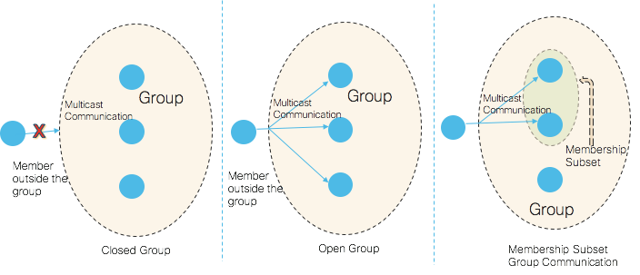
Picture 9: Group Types
In terms of drawing parallels with external software, ZeroMQ supports Group Messaging with some of the above features. Many other message brokers today support the Group Communication pattern. Also in IOS XR Group Communications, messages are queued on the subscriber, which attempts to avoid the problem of slow subscribers. ZeroMQ also supports this pattern.
Message guarantee semantics
IOS XR Group communication supports fire-and-forget, at least one, most, and all reliability semantics with respect to the number of far end entities from which the producer needs to receive acknowledgments.
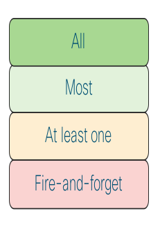
Picture 10: Group Communications Acknowledgement Options From Members
One can find similar semantics in Kafka and other messaging systems. For example, Kafka supports the following:
- No acknowledgement, fire and forget. Acks=0.
- Leader has persisted the message. Acks=1.
- Leader and all In Sync Replicas have persisted the message. Acks=All.
Similarly, RabbitMQ also has control over number of unacknowledged messages in flight.
Messaging protocols with pluggable transports
The messaging protocols in IOS XR have been developed with the required abstractions at the south bound layer so that they can be transported over various layers. For example, they can be transported over Ethernet, various switch fabric, Linux TCP/IP stack, IOS XR TCP/IP stack, etc. These protocols can also support multiple transport layers simultaneously. For example, Group Communications in CRS platforms is supported over Ethernet and switch fabric simultaneously. This is akin to ZeroMQ supporting multiple transports (inproc, ipc, tcp, pgm) to support threads in one process, processes in one box, processes in one network, and multicast group based communication.
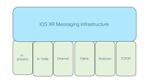
Picture 11: Group Communications Pluggable Transports
That concludes the first part. Take a break, refill your coffee and go to part two, where you can learn more about other concepts, such as data distribution & access design patterns, high availability and upgradeability architecture.
Leave a Comment